
Floating Car Observer – Approaches for Traffic
Management Strategies by Analysing Oncoming Vehicles
Franziska Wolf
1
, Sebastian Naumann
2
, Christoph Engel
3
and René Schönrock
4
Institut f. Automation und Kommunikation e.V. Magdeburg
Werner-Heisenberg-Str. 1, 39106 Magdeburg, Germany
Abstract. For traffic management systems, the knowledge of urban traffic con-
ditions is essential. The strategy of the Floating Car Observer (FCO) is to col-
lect traffic data via moving traffic sensors. The data of oncoming cars and
trucks is detected using a travelling public transport vehicle. Different acquisi-
tion strategies are evaluated to establish a low cost application, capable of real
time usage. Using the reflection of the infra-red emitter on number plates, traf-
fic data information about the speed and the average density of oncoming traf-
fic is acquired. The properties of the hardware prototype and the implementa-
tion of the software strategies are discussed and first research results are pre-
sented.
1 Motivation
Today knowledge of the inner-city traffic state is a prerequisite for a functioning traf-
fic management both in private and public transport. Data as speed and traffic density
is more and more used for applications on IT systems in public traffic management.
These services provide dynamic arrival time prognosis for passengers or sophisticated
traffic management strategies for public and private transport. Therefore widespread
acquisition methods for spatial and temporal traffic data are desired. The core prob-
lem offering such information services is the absolute knowledge of current and fu-
ture traffic conditions. Traffic processes can be described by several parameters, such
as the time headway τ, the traffic flow q and the local speed vl. The spatially and
temporarily complete automatic acquisition of these parameters is desirable, however
due to economical and technical reasons it is often not achievable.
1.1 Current Methods of Measuring Traffic Data
Currently the acquisition methods for traffic management systems rely on local detec-
tors such as induction loops, infra-red and video detectors at fixed cross sections ([1]
[2]) of a road (see c in Fig. 1). Unfortunately, these local measurements do not allow
the clear determination of traffic states. A second method is the instantaneous obser-
vation (see d in Fig. 1), however except for observation flights (see f in Fig. 1) this
method has only little practical relevance.
Wolf F., Naumann S., Engel C. and Schönrock R. (2008).
Floating Car Observer – Approaches for Traffic Management Strategies by Analysing Oncoming Vehicles.
In Proceedings of the 2nd International Workshop on Intelligent Vehicle Control Systems, pages 83-92
Copyright
c
SciTePress
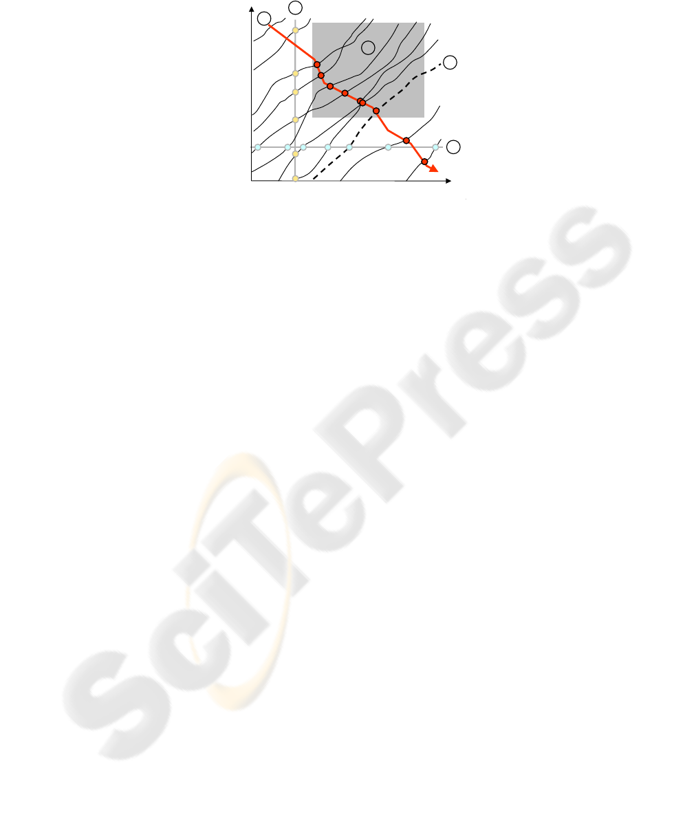
path
time
2
4
t
x
3
1
5
Fig. 1. Path time diagram of traffic course parameters.
An alternative to measuring traffic parameters with stationary devices is the use of
Floating Car Data (FCD). A vehicle is used as a mobile traffic sensor for permanently
transferring its own traffic data such as speed and position. As shown in e in Fig. 1,
kinematical parameters of single vehicles such as path x, velocity v and acceleration a
can be measured and travel times along road sections can be determined directly.
Thus FCD receives a small amount of information because the data only describes the
vehicle’s own driving course and does not represent traffic conditions in a broad
spectrum. If stuck in a traffic hold-up, the usage of a FCD vehicle can not offer in-
formation about the length of the hold-up and the estimated time lag for the travel
time prognosis. FCD is dependent on the traffic situation which it is going to meas-
ure.
1.2 Floating Car Observer
A broader data acquisition method will be the automatic observation of oncoming
traffic in order to obtain traffic data. The main idea is that public transport vehicles
shall carry devices which can observe traffic conditions on the opposite oncoming
lanes. Equipped with low-cost devices, vehicles will be used as Floating Car Observ-
ers (FCO) monitoring their road environment and traffic flows along the public trans-
port route network [3]. The advantage of the FCO approach is shown in Fig. 1. The
ongoing course g shows that traffic density k(x) and speed v(x) can be measured
directly. The FCO measures the traffic data without being part of the traffic situation.
For example the starting points and the length of traffic hold-ups on the oncoming
traffic lanes can be observed and used to improve arrival time prognosis of the public
transport distributed by various services.
By using this data, traffic diversions can be adapted for present traffic situations.
In the future the traffic data acquired by the FCO module will be sent by GPRS to
a traffic management control centre. Additionally the FCO’s geographical position,
driving direction and speed will be used to generate a continuous overview of the
network`s current traffic conditions. In thefollowing, the simulation set up to evaluate
various potential FCO devices is presented. It will be tested if the device data can be
84

used for signal processing algorithms for speed and traffic density calculation. The
most promising technical strategy will be used for a hardware and software prototype
of a FCO.
In this paper, methods of observing vehicle flows in order to gain information about
traffic conditions will be outlined. In Section 2 the theoretical background of a system
observing oncoming traffic using a Floating Car Observer (FCO) is describes. The
simulation framework to evaluate different sensors to set up a hardware prototype is
outlined. Furthermore it can be shown that the theory of observing oncoming traffic
can be realised. In Section 3, a description of the FCO’s hardware design is pre-
sented. The strategy of using an infra red (IR) emitter combined with a camera to
capture specific traffic observing images will be described. The currently developed
image processing algorithms to detect traffic vehicles will be described along with the
expected results. A conclusion and an outlook at the upcoming steps will conclude
the article.
2 FCO Design - Simulation and Evaluation
In preparation for running a computer simulation of the FCO, a model of a public
transport vehicle can be equipped with simulated FCO devices such as laser scanner,
ultrasonic and video camera systems. These simulated and evaluated devices are al-
ready broadly used applications for supporting driver-assistance ([4][5]) and safety
applications [6] for example in nighttime situations [7]. However so far they are
hardly used for oncoming traffic detection and observation. By altering the configura-
tion of the FCO devices, the different detection rates of the sensors are measured
while the vehicle travels through a virtual public transport network, built using a mi-
croscopic traffic model of a real existing traffic scenario. Based on empirical values,
the simulation evaluates whether the resolution of the devices is appropriate to
achieve a detection of the oncoming traffic. For example it was measured to which
quantity and distance the FCO sensor types could capture the oncoming vehicles due
to the frame rate, detection field and measure values.
In order to equip vehicle fleets of public transport companies with FCO devices,
also economical aspects of the systems have to be considered. In this evaluation the
sensor types are simulated in a FCO simulation and evaluated as follows:
85
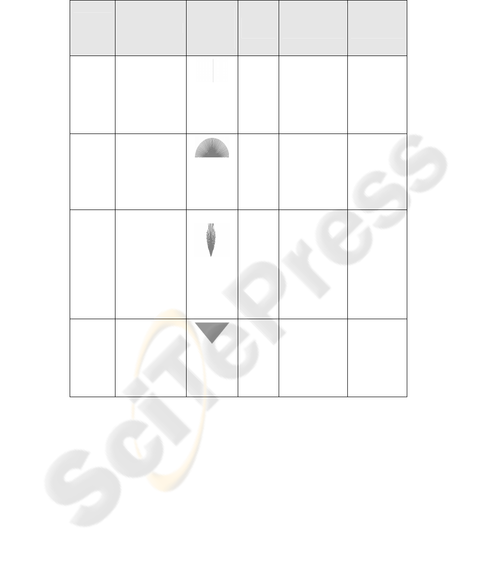
Table 1. Tested sensor types simulated and evaluated on usability for FCO development.
FCO-
sensor
type
Function
Field of
detection
and measure
values (Hz)
Range
(m)
Disadvantages
for FCO usage
Advantages
for FCO usage
Light
scanner
The sensor sends
a directed laser
light beam. The
reflection is used
to calculate dis-
tance
1, 4, 16, 64
20 Discrimination
of traffic vehi-
cles hardly
achievable
Only 1-D resolu-
tion
Low acquisi-
tion costs
Laser
scanner
The laser scanner
contains a rotat-
ing unit, which
sends pulsed laser
beams
19, 38, 75
150 Discrimination
of traffic vehi-
cles hardly
achievable
High acquisition
costs
Wide range of
150m
High spatial
and temporal
resolution
Ultra-
sonic/
Radar
The ultrasonic
sensor sends
sound/ electro-
magnetic waves
where the detec-
tion field forms a
club. The reflec-
tion is used to
calculate dis-
tances
10
10 / 50 Discrimination
of traffic vehi-
cles hardly
achievable
Calibration of
measuring field
required
Low acquisi-
tion costs
Much experi-
ence of this
technology in
traffic moni-
toring
Active
video
camera
The camera sys-
tem uses pulsed
IR lights to rec-
ognise retro-
reflecting materi-
als, e.g. number
plates.
30 to 60
NN
(weather
condi-
tions)
Detection range
depending on
weather condi-
tions
Low acquisi-
tion costs
Discrimination
of traffic vehi-
cles achiev-
able
The evaluation showed that the ultrasonic system has an insufficient usability due to
the limited range and specific formed detection field. The laser and ultrasonic sensors
may need a second sensor to enable a sufficient range and detection accuracy for traf-
fic data capturing. Due to high acquisition costs, the laser scanner can also not be
used for broad traffic monitoring. The camera approach uses positions and sizes of
detected objects for data reconstruction. Due to better discrimination of detected ob-
jects, a camera system is higher rated than a laser or an ultrasonic system.
The camera based system has been rated to be the most promising system due to
its technical properties, low cost and mounting capabilities. The main advantage of
86
the camera system is its potential for detecting particular objects, cars in this case.
However image streams received by a camera system normally are not very signifi-
cant: but by using an active exposure system the images’ quality and therefore the
initial position for object recognition can be improved. The usage of such camera
systems for traffic monitoring has been proposed, for example for automatic number
plate recognition systems [8]. A special system using a similar strategy was originally
developed for the recognition and safety improvement of non-motorised, vulnerable
road users such as pedestrians or cyclists [9][10]. Equipped with special coated retro-
reflectors they could be recognised in IR exposed image streams by object detecting
algorithms. Normally cars and trucks are not equipped with such special coated retro-
reflectors of this quality, but they provide a slightly retro-reflecting number plate.
These number plates have proportions from height to width which are in most coun-
tries unique among road signs and other reflecting objects in the road environment. It
is essential to identify these reflecting number plates because their shapes will be
used for traffic data calculation. By scanning the image streams of the camera, the
size and movement of the detected number plates are used for vehicle monitoring and
speed reconstruction using geometrical strategies such as intercept theorems.
The following section describes the set up of a hardware and software prototype of
a FCO device for visual traffic observation. The usage of embedded infra-red light for
detecting number plates of cars in video streams will be dealt with. The set up and
configuration of the specified camera system is also described. The current research
strategy of the vehicle detecting image processing and speed reconstruction algorithm
will be described and implementation methods will be outlined. First results based on
images of the simulation are presented.
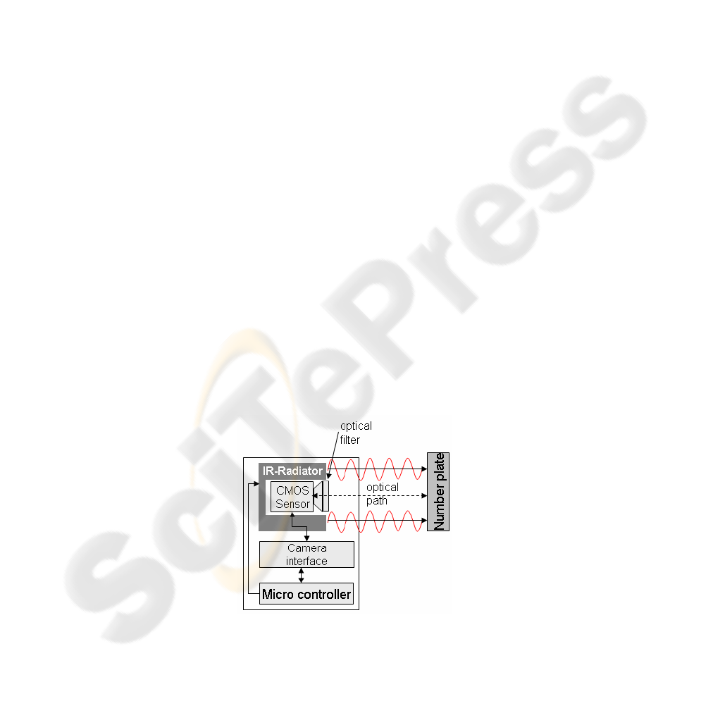
3 Technical Design of the FCO Prototype
The architecture of the FCO prototype is described in Fig. 2 and contains the follow-
ing modules:
• CMOS-camera with optical filter for achieving the raw image stream
• Infra-red-emitter for lighting the scenery
• Micro controller
Fig. 2. FCO camera module for recognizing number plates.
87
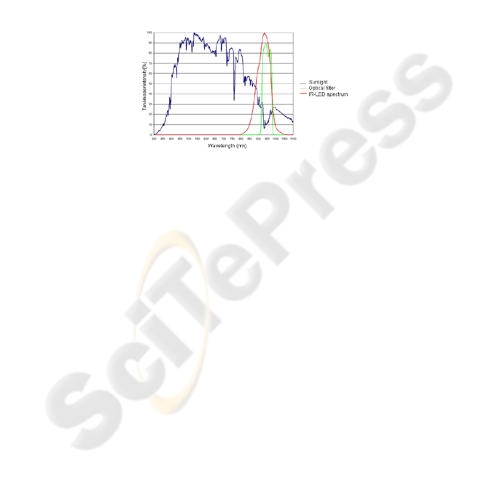
The low cost camera module is based on CMOS technology and includes a 12 bit
ADC (analogue-to-digital converter). 30 monochrome 12 bit raw images with a reso-
lution of 648*488 pixels can be captured per second. The emitted IR light has a nar-
row-banded spectrum with a central wavelength of 950 nm. This compact spectrum
of the IR emitter enables the usage of a special optical filter in order to improve the
quality of the images received by the camera system. As pointed out in
Fig. 3 the opti-
cal filter reduces the receivable spectrum of the camera to the wavelength from 900
nm to 1000 nm. That reduces the distracting sun light in order to improve the signal-
to-noise ratio and therefore makes it easier to detect objects which reflected the IR
light..
Fig. 3. Spectral sensibility of CMOS sensor with and without optical filter.
The 32 bit ARM microcontroller synchronises the switching and the power control of
the IR LED emitter. Provided by the digital camera via a serial I²C interface, the
micro controller also runs the image processing and object recognition and tracking
algorithms. An overview of the software design and the main modules is described in
the following section.
4 Image Processing and Object Recognition Strategies
In this section the basic image processing algorithm will be outlined. The algorithm
uses a 12 bit raw data image for input provided by the camera system. During the
exposure, the aperture of the camera and the IR emitter are synchronised with each
other in order to create video images with good detectable objects. The on and off
switching of the infra-red emitter can be synchronised to the camera in two different
ways, shown in Table 2.
88
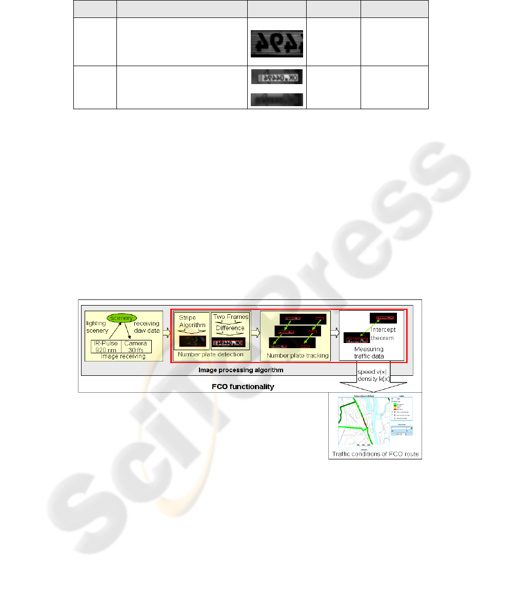
Table 2. Two methods of IR embedded image processing.
Function Image Advantages Disadvantages
Stripe
Algorithm
Every second line of a frame is ex-
posed by the infra-red emitter.
Generates bright and dark striped
pattern for reflecting objects.
Small amount
of data
Lower resolution.
Distortion of
reflections
possible.
Two
Frame
Algorithm
Every second frame is exposed by
the infra-red emitter. Generates
bright patterns for reflecting objects
Allows a
more accurate
calculation
High amount
of data
Both algorithms are able to achieve specified video frames. The Stripe Algorithm
allows a fast processing rate, but a lack of exposure can lead to an insufficient object
recognition. The Two Frame Algorithm allows a more accurate calculation but needs
double the amount of data of the first strategy. It has to be researched which strategy
is the best for the following object recognition algorithm shown by the application
flow in Fig. 4. The process flow starts with the exposure of traffic scenery to create
raw data images to enable clearly visible highlighted areas based on IR reflection on
vehicle number plates. These rectangular areas have to be detected by the algorithm
in each frame. The next step is to track each of these rectangles from frame to frame.
This is done using position and size of the rectangles as similarity measures. Traffic
data of the detected cars can be computed using the number plates’ course through
the images. It has been analysed for the image processing algorithm done by the mi-
cro controller, whether the usage of Java or the specified Open CV libraries for C++
can accomplish these tasks best. These steps are marked red in the application flow.
Fig. 4. Vehicle detection and data reconstruction of FCO.
The following pseudo code presents the steps of the rectangle detection in the raw
data images, the number plate tracking and the measurement of the traffic data. For
the following FCO algorithm in pseudo code, the following variables are to be men-
tioned:
89

• lrf, lrc – list of the rectangles found in the current frame, the rectangles’ course
• h(NPfn), h(NPf1) – height of the rectangle in the first/ last captured frame
• h(NPR) – real height of a number plate
• fd – focal distance of the camera system used
• hit - threshold condition fulfilled
FCO algorithm describing the number plate detection, tracking and traffic data calculation.
FCO ALGORITHM
for (every recorded frame) do
{
while (the lower right corner of the frame is not reached)
{
browse image;
if (hit)
{
create rectangle with a dimension of 0;
while (new hit in the area of the rectangle)
{
rectangle increased until includes new hit
}
}
if (r NOT (ratio 52:11 OR 34:20))
{
remove r;
}
}
store all remaining rectangles of frame as list lrf;
for (the last added rectangle (rlast in lrc)) do
{
for (every rectangle (r in lrf)) do
{
if ((dist(center of rlast and r)) < thresholddist)
{
add r to lrc;
remove r from lrf;
}
}
}
for (every rectangle remaining in lrf) do
{
create new list lrci with rectangle as first element;
}
for (every list lrci without a new rectangle added,
rectangle course is assumed as finished) do
{
s1 = h(NPf1) / h(NPR) * fd;
sn = h(NPfn) / h(NPR) * fd;
t = tn – t1
s = sn – s1
v = s/t;
print out v;
delete lrci;
}
}
In order to track the patterns in each image, previous knowledge about the movement
of the number plates has to be used. Because of the high frame rate of up to 30
90

frames/sec, the position of a rectangle in one frame can be assumed similar in the next
frame. While tracking the rectangles of the video frames, the change of size and posi-
tion of the rectangles from frame to frame is used to reconstruct the speed of the de-
tected vehicles using intercept theorems.
Recent test results show that the algorithm works well for simulated streams and
encouraging results for first captured images of the FCO hardware prototype could be
achieved.
Before the FCO module can be integrated into a public transport vehicle, broad
field tests will be necessary. For this a test vehicle is equipped with the required
measuring and computing technology. The equipped test vehicle will be used for
broad test scenarios covering data acquisition in varying seasonal weather situations
at selected places.
5 Conclusions and Future Prospects
This paper offers a new approach to acquire data of actual traffic situations using a
Floating Car Observer (FCO). The FCO captures data of the traffic situation of on-
coming vehicles, such as positions and lengths of traffic hold-ups. The captured data
will be used to enhance travel time prognosis for public traffic management systems.
A simulation framework was used to evaluate different traffic observing devices (la-
ser, ultrasonic, camera) in order to to set up a traffic monitoring FCO prototype. The
evaluation derives from detection rates, but also from real time capability of the com-
puting process and economical aspects of the devices. The system chosen to set up a
FCO prototype comprises of video processing and infra-red emitting modules. The
reflection of the infra-red beams on vehicles’ number plates shall be used to gain in-
formation about speed and average density of the oncoming traffic. The algorithm
presented detects the highlighted patterns of reflection and tracks them. Using inter-
cept theorems, the courses of the number plate reflections are used to extract traffic
data such as traffic density and speed. The algorithm is currently implemented and
tested on various platforms. In future this traffic information will improve manage-
ment systems of the public transport to inform passengers about broad traffic situa-
tions and estimated arrival times.
At present the set up of the FCO prototype is used for image capturing of traffic
scenarios. These real images have been used together with synthetic simulation im-
ages to develop the presented algorithm. In this respect currently different platforms
and system frameworks are tested for the implementation of the algorithm. The soft-
ware has to be evaluated on different traffic road situations, seasonal and weather
conditions. Analysis of the detection rates under different weather and seasonal con-
ditions will reveal their implementable capacities and limits. Additionally it will be
examined as to which traffic condition the system can be best applied to and which
kind of traffic data is the most significant for traffic management systems. Consoli-
dating the most effective data into global strategies will be the next step towards ad-
vanced public and private traffic management systems.
91

References
1. Minakata, T. Taniguchi, Y. Shiranaga, H. Nishihara, T.: Development of Far Infra-red
Vehicle Sensor System, Sei Technical Review – English edition, ISSU 58, Sumitomo elec-
tric industries LTD, Japan (2004) 23-27
2. Sumiya, N.; Fujihira, K.; Kamijo, S.: Incident detection system by sensor fusion network
employing image sensors and supersonic wave, Proceedings of the Intelligent Transporta-
tion Systems Conference, 06. IEEE Volume, (2006), 1066 - 1071
3. Hoyer, R.; Czogalla, O; Naumann, S.: Improvement of real time passenger information by
floating car observers, Proceedings of the 13th World Congress on Intelligent Transport
Systems, London (2006)
4. Nagata Akihito, Ozawa Shinji, Yanagawa Hirohiko, “Approach Vehicle Detection from the
Rear Side Using Fish-eye Camera”, Papers of Technical Meeting on Information Process-
ing, IEE Japan, Vol. IP-07; No. 1-13; (2007), 65-70
5. Wannes van der Mark, Dariu M. Gavrila, “Real-time dense stereo for intelligent vehicles”,
Intelligent Transportation Systems, IEEE Transactions on Publication Date: March 2006,
Vol 7, Issue 1, 38-50
6. Lages, Dr. U.: Laser Sensor Technologies for Preventive Safety Functions. IBEO Publica-
tion 12th International Symposium ATA EL 2004
7. Graf, T.; Seifert, K.; Meinecke, M.; Schmidt, R.:Advanced Night Vision Systems Con-
cepts, Conference Title 12th World Congress on Intelligent Transport Systems, 12th World
Congress on Intelligent Transport Systems, San Francisco, 06. -11.11. 2005, Proceedings
8. Sulehria, H.; Zhang, Y.; Irfan, D: Mathematical Morphology Metodology for Extraction of
Vehicle Number Plates, International Journal of Computers, Issue 3, Volume 1, 2007
9. Hoyer, R.; Schönrock, R.: Approach to the Recognition of non-motorised Road Users,
Proceedings of the 8th World Congress on Intelligent Transport, Sydney (2001)
10. Hoyer, R.; Herrmann, A.; Schönrock, R: Modelling of vehicle actuated traffic lights. In:
Schulze, Th. Et al.: (Hrsg.): Simulation und Visualisierung 2004. Society for Modeling and
Simulation International SCS-European Publishing House, Erlangen, San Diego, 2004,
S. 359 – 369; ISBN 3-936150-30-3.
92
