
LOSS MINIMIZATION OF INDUCTION GENERATORS WITH
ADAPTIVE FUZZY CONTROLLER
Durval de Almeida Souza*, José Antonio Dominguez Navarro**
* Federal Center for Technology Education of Bahia – CEFET-BA/ UE de Vitória da Conquista
3150 Zabelê, 45030-220, Vitória da Conquista, Bahia, Brazil
Jesús Sallán Arasanz
** University of Zaragoza, Department of Electrical Engineering, Calle Maria de Luna s/n
50018 Campus del Actur, Zaragoza, Spain
Keywords: Inverter-fed induction generator, loss minimization, vector control, fuzzy controller, adaptive control.
Abstract: In this paper a new technique for efficiency optimization of induction generator working at variable speed
and load is introduced. The technique combines two distinct control methods, namely, on-line search of the
optimal operating point, with a model based efficiency control. For a given operating condition,
characterized by a given turbine speed (ω
T
) and electric torque (T
e
), the search control is implemented via
the “Rosenbrock” method, which determines the flux level that results in the maximum output power. Once
the optimal flux level has been found, this information is used to update the rule base of a fuzzy controller,
which plays the role of an implicit mathematical model of the system. Initially, for any load condition the
rule base yields the rated flux value. As the optimum points associated with the different operating
conditions are identified, the rule base is progressively updated, so that the fuzzy controller learns to model
the optimal operating conditions for the entire torque-speed plane. After every rule base update, the
Rosenbrock controller output is reset, but it is kept active to track possible minor deviations of the optimum
point.
1 INTRODUCTION
In the last decade, wind power is integrated into the
electrical grid and accounts for a noticeable share of
the total power generation (
Kumar, 2007). In this
context the inverter-fed induction generator has been
identified as a possible source of energy to be used
in modern micro and high power applications
(
Leidhold, 2002). The presence of a converter in a
drive system enables an extra degree of freedom,
namely, flux adjustment. In fact, efficiency
optimization in adjustable speed drives is usually
obtained by machine flux control. This is due to the
fact that in electric machines, maximum efficiency is
achieved when the copper losses become equal to
the core losses. Typically, under partial load
operation, rated flux condition results in relatively
large core losses, small copper losses, and poor
efficiency. By decreasing the flux, core losses are
reduced, whereas an increase in copper losses takes
place. The total losses, however, are reduced, and
the efficiency is improved (
Sousa, 1995). In this
work, a new efficiency optimization technique is
introduced. It is applicable to any adjustable speed
drive, but it is illustrated here for an induction
generator under field-oriented control. The
technique combines two distinct control strategies,
namely, on-line search and model base control. For a
given operating condition, characterized by a given
turbine speed (ω
T
) and electric torque (T
e
), the
search control is implemented via the Rosenbrock
method, which determines the flux level that results
in maximum output power. Once the optimal flux
level has been found, this information is used to
update the rule base of a fuzzy controller, which
plays the role of an implicit mathematical model of
the system. Figure 1 shows the scheme of the
Inverter-Fed Induction Generator used in this
research.
13
de Almeida Souza D., Antonio Dominguez Navarro J. and Sallán Arasanz J. (2008).
LOSS MINIMIZATION OF INDUCTION GENERATORS WITH ADAPTIVE FUZZY CONTROLLER.
In Proceedings of the Fifth International Conference on Informatics in Control, Automation and Robotics - ICSO, pages 13-19
DOI: 10.5220/0001482500130019
Copyright
c
SciTePress
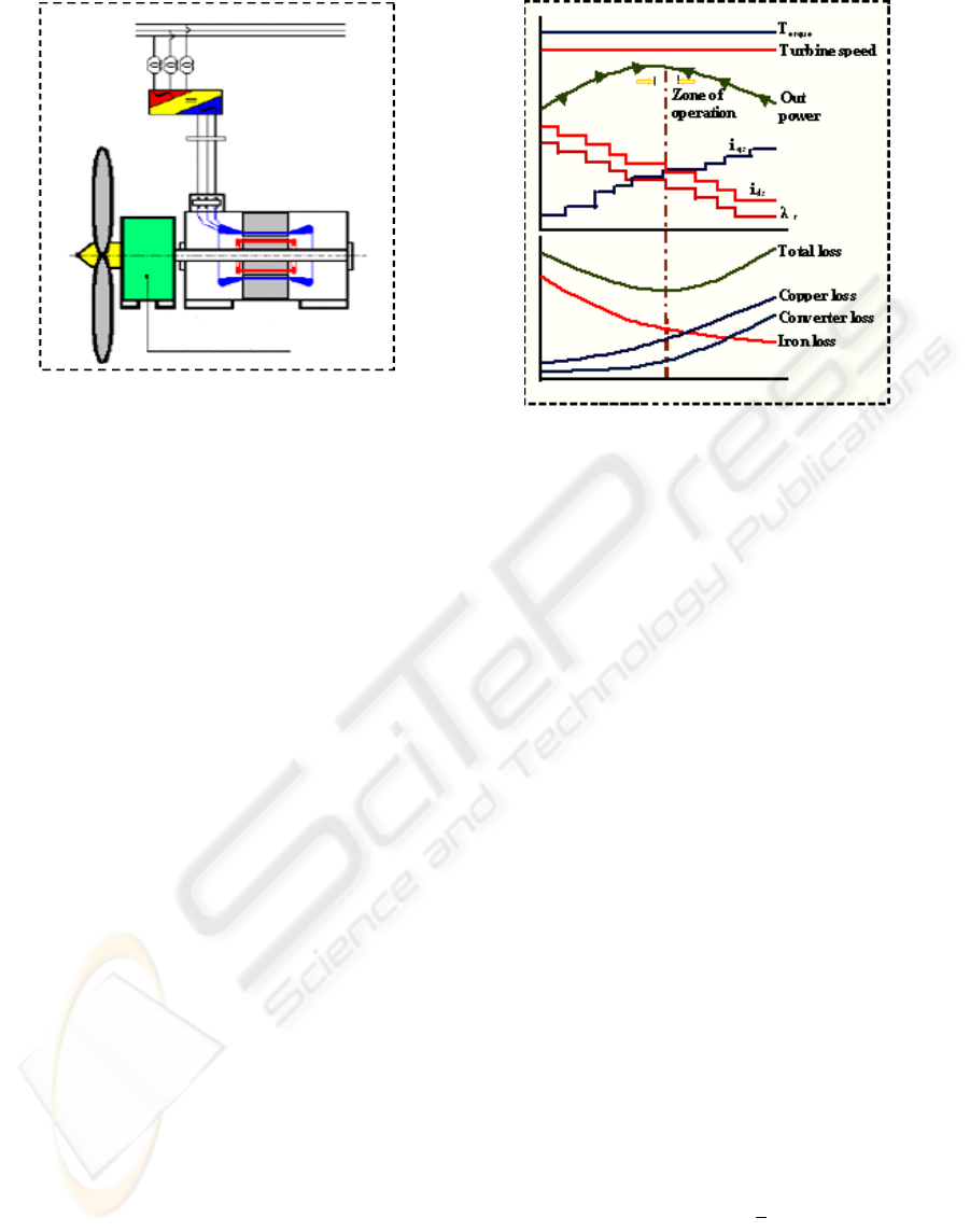
Figure 1: Inverter-fed induction generator connected to
grid. Figure adapted by (Rüncos).
2 EFFICIENCY OPTIMIZATION
2.1 Search Control
In steady state with constant torque and speed, the
flux component of the chain is decreased whereas
the torque component is increased. Initially a
reduction in total stator current occurs (I
s
= i
qs
- j i
ds
),
and consequently a reduction in stator copper losses,
but rotor copper losses are increased. As the
reduction in both stator and iron losses are higher
than the increase in rotor losses, the total losses are
reduced. If i
ds
is continuously reduced, a reduction in
the total losses will occur until the moment when the
increase in copper losses becomes higher that the
reduction in core losses, that is, the point minimum
losses will be exceeded. The determination of this
point, of minimum losses, that corresponds to
optimum efficiency, can be performed using
different procedures. This philosophy is illustrated in
figure 2.
A turbine is submitted to a load proportional to the
square of the angular speed of the wind. Thus, in
weak wind conditions, below 7 m/s, the generator
works typically with light rotor load. In such
conditions the intensity of the rotor flux of the
induction generator (IG), commanded in vector
control for i
ds
, can be reduced to values below
nominal flux, reducing reactive circulation,
diminishing iron losses and consequently increasing
global efficiency of both inverter and machine
(Sousa,1995), something essential at low wind speed
to improve power extraction capacity, (Simões,
1999).
Figure 2: Philosophy for search method of efficiency
optimization.
As mentioned before, rated flux results in excessive
core losses and poor efficiency under light load
conditions. Another aspect worth mentioning is the
need to prevent machine torque disturbances during
the efficiency optimization control. Under vector
control, the developed torque can be expressed as:
qsrte
ikT
λ
=
(1)
where: λ
r
is the rotor flux and i
qs
is the torque
component of the stator current, and k
t
is a constant.
If the flux is reduced to improve efficiency, i
qs
must
be increased accordingly, such that their product
remains constant at any given time.
2.1.1 The Rosenbrock Method
This is a very simple method, and guaranteed to
converge. The reference for the flux component of
the stator current (i
ds
*
) is modified in small steps in a
given direction, while the system approaches the
optimum efficiency point, i.e., the measured change
in output power in the n-th step is positive (ΔP(n) >
0). When the method recognizes that an “overshoot”
has occurred (ΔP(n) < 0), it reverses the search
direction, with a reduced step size, (J. Moreno-
Eguilaz, 1997,). The search process can be
mathematically expressed as in (2):
0P(n) if ;
2
1
0P(n) if ;1
);()()1(
***
⎪
⎩
⎪
⎨
⎧
<Δ−=
>Δ=
Δ+=+
k
k
niknini
dsdsds
(2)
where:
Δ
P(n) = P(n) – P(n-1)
and
Δ
i
ds
*
(n) =
i
ds
*(n) – i
ds
*(n-1) .
Gear
box
ICINCO 2008 - International Conference on Informatics in Control, Automation and Robotics
14

3 THE PROPOSED SYSTEM
The indirect method of vector control is applied to
the IG. It derives the reference for the torque
component of the stator current (i
qs
*
) from the speed
error, utilizing a conventional proportional-Integral
(PI) controller. As the system operates with variable
flux, a compensation block is introduced at the
output of the speed PI controller. Essentially, this
block multiplies the original PI controller output by
the ratio rated flux / actual flux (estimate).
The reference for the flux component of stator
flux (i
ds
*
) is not kept constant here, as in the majority
of high performance IM drive systems. It is defined
as the sum of two block outputs: i
ds
*
(k) = i
ds
’*
(k) +
ΣΔi
ds
*’
. The first term (i
ds
’
*
) is obtained from a fuzzy
controller, that from two inputs (speed (ω
r
) and
estimate load torque(T
L
), derives a preliminary
reference (i
ds
’*
) through fuzzy inference. The second
one (ΣΔi
ds
’
*
) is the actual output of a search
controller, based on the Rosenbrock method. Its
value represents the accumulated control actions
taken by the controller during the search process up
to the current iteration (n), as can be seen in Fig. 3.
When the system is turned on for the first time,
the rule base of the fuzzy controller contains rated d-
axis current reference (i
ds
’
*
) for all rules, i.e. for any
speed and load torque point. When a steady state
condition is detected, the search controller becomes
active. After a few steps, it reaches the optimum
efficiency point by imposing the ΣΔi
ds
’
*
change to
the original reference (i
ds
’
*
) from the fuzzy
controller. Once the controller recognizes this
optimum condition, the rule base can be updated to
reflect the knowledge of the optimum flux level for
this particular operating point (load torque and
speed). At the same time, the search controller
output must be reset, to prevent erroneous operation.
When the optimum point is found, the rule base is
updated, and the output of the search controller
reset, such that, effectively, i
ds
*
opt
= i
ds
’*
.
Figure 3: Hybrid efficiency controller.
As the optimum efficiency points related to the
several operating conditions are identified, the rule
base is progressively updated, such that the fuzzy
controller “learns” the optimum flux level for the
entire torque-speed plane. Once completed the
learning process, the output of the fuzzy controller
already reflects the optimum flux level, and the
fuzzy controller is capable of driving the system at
optimum efficiency without delays. To prevent sub-
optimal operation, the search controller remains
active to track possible deviations of the optimum
point. Under transient conditions, the search process
is cancelled, and the flux reference is solely derived
from the fuzzy controller. It is worth noticing that no
switching of strategies is required, since higher
torques demands are normally met by imposing
higher flux levels, i.e., the optimum level of flux for
higher torques is close to the rated flux value. This
methodology is summarized in Figure 4.
Figure 4: State diagram for efficiency controller.
3.1 The Fuzzy Efficiency Controller
The fuzzy sets for the input variables are shown in
Figure 5. Both utilize normalized universes of
discourses, to make the controller easier to port for
different machine ratings. The output variable (i
ds
’*
)
is represented by singletons, and is not shown here.
The rule base for the fuzzy controller is illustrated in
LOSS MINIMIZATION OF INDUCTION GENERATORS WITH ADAPTIVE FUZZY CONTROLLER
15

Table 1. It is typically initialized with rated
i
ds
’
*
(1 p.u.), and it is progressively updated to
incorporate the knowledge of the maximum
efficiency points as they are found by the search
controller, as previously described.
Table 1: Rule base for the fuzzy controller.
The primary flux reference current i
ds
’*
is obtained
by fuzzy sup-min inference, and the height method
of defuzzification:
(1)
'
D
in Ri
iA
D
Ri
iA
ds
I
i
μ
μ
+
∗
=
=
×
=
∑
∑
(3)
At steady state condition, whenever the search
controller identifies an optimum flux level, the rule
base must be updated. This process can be
summarized as follows:
1) Identify the fired rules in the Rule Base (e.g.,
rules A,B,C,D in Table 1);
2) Compute the degree of truth for each rule, by
applying the minimum (min) operator over the
degree of membership for the input variables T
L
and
ω
r
: μ
Ri
= min(μ
Tl
, μ
ωr
);
3) Evaluate the proportionality factor K, given
by (4);
2
()
D
Ri ds
iA
D
Ri
iA
ipu
K
μ
μ
=
=
×Δ
=
∑∑
∑
(4)
4) Compute the correction term ΔI
i
(n)=Kxμ
Ri
for
each fired rule as the product of its degree of truth
and factor K;
5) Get the new value for each fired rule i
(i=A,B,C,D) by (5).
(1) () ()
iii
In In In
+
=+Δ
(5)
3 SIMULATION RESULTS
In this simulation a 4 kW squirrel-cage induction
machine was used (220/380V, p=2). A reference
speed step of 0.88 p.u, 0.40 p.u, 0.88 p.u and 0.40
p.u is applied at t=1s, t=30s, t=45s and t=55s,
respectively, as shown in Figure 6 (A). After the
initial transient, at t=6s, the search begins. At t = 15s
the controller identifies that an optimum point has
been found, and proceeds to update the rule base. Up
to this point, the output of the fuzzy controller (i
ds
’*)
was the rated value for magnetizing current, but
from this time on, its output is made equal to the
optimum value. Simultaneously, the output of the
search controller is reset (∑Δi
ds
= 0), as can be seen
in Figure 6 (B). The rotor flux response follows a
first order filter profile of the reference current (i
ds
*)
as expected, and is shown here multiplied by a factor
of 10, Figure 6 (C). The changes in flux level have a
direct impact on the output power, Figure 6 (E), as
well as in the torque component of stator current
reference (i
qs
*
), as expected, but the electromagnetic
torque is unaffected, due to proper feed-forward
compensation in i
qs
*
, as shown in Figure 6 (D). At
t=45s and t=55s when a previous reference speed
step is applied, the rule base recognize and the
system operate directly with optimum efficiency.
Figures 6 (F) and (G) shown the voltages and
currents on the phases A, B and C, respectively.
T
L
(p.u.)
0.1
0.2
0.3
0.4
0.5
0.6
0.7
0.8
0.9
1.0
1.0
0.5
Z
S
M
L
μ
(a)
(b)
ω
m
(p.u.)
0.1
0.2
0.3
0.4
0.5
0.6
0.7
0.8
0.9
1.0
1.0
0.5
Z
S
M
L
μ
Figure 5: Fuzzy sets for the input variables: (a) load
torque and (b) speed.
ICINCO 2008 - International Conference on Informatics in Control, Automation and Robotics
16

0 10 20 30 40 50 60
0
200
400
600
800
1000
1200
1400
0 10 20 30 40 50 60
0
200
400
600
800
1000
1200
1400
Turbine Speed (r.p.m.)
N
g
N
g
*
t (s)
(r.p.m.)
(r.p.m.)
A)
0 10 20 30 40 50 60
-4
-2
0
2
4
6
8
t (s)
Current (A)
ΣΔ
i
ds
*
i
ds
*
i
ds
'*
B)
0 10 20 30 40 50 60
0
200
400
600
800
1000
1200
Out P ower (W )
t (s)
P
o
(W)
E)
0 10 20 30 40 50 60
-150
-100
-50
0
50
100
150
t (s)
Voltage (V)
Va, Vb and Vc (Volts)
F)
0 10 20 30 40 50 60
2
3
4
5
6
7
8
Flux (Wb) and Flux Component (A)
i
ds
*
λ
(A)
r
(Weber)
t (s)
C)
0 10 20 30 40 50 60
-20
-15
-10
-5
0
5
Torque (N.m) and Torque Component (A)
T
e
(Nm)
i
qs
(A)
t (s)
D)
LOSS MINIMIZATION OF INDUCTION GENERATORS WITH ADAPTIVE FUZZY CONTROLLER
17

Figure 6: Results of simulation for operation of the fuzzy
controller: A) Reference and actual speed on the axis of
turbine in r.p.m.; B) Components of d-axis current; C)
Components of d-axis current and rotor flux; D)
Components of q-axis current and torque estimate; E) Out
power; F) Voltage in the phases A, B and C; F) Current in
the phases A, B and C.
4 CONCLUSIONS
The proposed control strategy consists of a more
effective way to implement the efficiency
optimization via flux control in an induction
machine. From the analysis of literature can be
observed that in the comparative study of the diverse
known search techniques, none of them results on a
process as fast as the one achieved with the present
method. This implies a great energy save, because
the system can be tuned all the time and operate at
maximum efficiency. Another noteworthy point is
that the transition from steady to transitory state
occurs without abrupt changes in the system, or
without any topological control change, since the
displacement from a low torque point to one of
higher torque or vice-versa is already programmed
in the base of rules. The salient features of this
technique are summarized next: i) It is applicable to
any machine size, and does not require knowledge of
machine parameters; ii) The rule base self tuning is
progressive, and does not need any intervention
from the operator; iii) Once tuned, the system is
capable of operating all the time at optimum
efficiency, without delay from one steady state
condition to another, with significant energy saving;
iv) During transients the rule base is kept active and,
as a consequence there is no switching from one
control strategy (for steady state) to another (during
transients), provided that the tuning has been
completed; v) Proper disturbance compensation is
included, such that no correction is needed to keep
torque and speed constant during the optimization
process; and vi) The system is capable of tracking
slow parameter deviations, guaranteeing true
optimum efficiency.
ACKNOWLEDGEMENTS
The authors wish to acknowledge the support of Fha
– Foundation for the Development of New
Technologies of Hydrogen in Aragón; CIRCE –
Centre of Research for Energy Resources and
Consumption; as well as CEFET-BA and University
of Zaragoza.
REFERENCES
Kumar,Vinod and Joshi, R. R. 2007. Fuzzy Logic Based
Light Load Efficiency Improvement of Matrix
Converter Based Wind Generator System. In Journal
of Theoretical and Applied Information Thecnology,
pp. 79 – 89. JATIT.
Leidhold, Roberto, Garcia, Guillermo and Valla, Maria
Inés. February 2002. Field-Oriented Controller
Induction Generator With Loss Minimization.
Transactions on Industrial Electronics. Vol. 49. No 1
pp. 147-156, February 2002. IEEE.
Sousa, G. C. D. and B. K. Bose, (1995), Fuzzy logic based
on-line efficiency optimization control of an indirect
vector controlled induction motor drive, Transactions
on Industrial Electronics vol. 42 nº 2, pp. 192-198.
IEEE.
Rüncos, F. at alli, Geração de Energia Eólica -
Tecnologias Atuais e Futuras. WEG Jaraguá do Sul.
Brasil. www.weg.com.br. WEG Máquinas S.A.
Simões, Marcelo Godoy, Franceschetti, N. N. and BOSE,
Bimal Kumar. 1999. Otimização de um Sistema de
Geração de Energia Eólica Através de Controle Fuzzy.
SBA Controle & Automação. Vol. No 01, pp. 48-58.
Brasil. Jan., Fev., Mar., Abril de 1999. SBA.
Sousa, G. C. D., Bose, B. K. and J. Cleland, (1992), “Loss
Modeling of Converter Induction Machine System for
Variable Speed Drive”, Proceedings of the IECON’92,
International Conference on Industrial Electronics,
Control and Instrumentation, vol. 1, pp. 114-120.
IECON.
F. Abrahamsen, Fred Blaabjerg,J. K. Pedersen, P. Z.
Grabowski and P. Thogersen, (1998), On the Energy
Optimized Control of Standard and High-Efficiency
Induction Motors in CT and HVAC Applications,
Transactions on Industry Applications, vol. 34, nº 4,
pp. 822-831. IEEE.
F. Abrahamsen, Fred Blaabjerg,J. K. Pedersen, (1996),
State –of-the-Art of optimal Efficiency Control of
Low Cost Induction Motor Drives, Power Electronics
and Motion Control, vol. 2, pp. 163-170. PEMC’96.
0 10 20 30 40 50 60
-20
-15
-10
-5
0
5
10
15
20
t (s)
Current (A)
Ia,Ib and Ic (A)
G )
ICINCO 2008 - International Conference on Informatics in Control, Automation and Robotics
18

J. Moreno-Eguilaz, Miguel Cipolla, Juan Peracula, Paulo
J. da Costa Branco, (1997), Induction Motor Optimum
Flux Search Algorithms with Transient State Loss
Minimization Using a Fuzzy Logic Based Supervisor,
Power Electronics Specialists Conference, 28th,
Annual IEEE, vol. 2, pp. 1302 – 1308.
Souza, Durval de Almeida, Aragão Filho, W. C. P. and
Sousa, G. C. D. August 2007. Adaptive Fuzzy
Controller for Efficiency Optimization of Inductions
Motors. Transactions on Industrial Electronics, Vol
54, No 4, pp2157-2164. IEEE.
Leidhold, Roberto, Garcia, Guillermo and Valla, Maria
Inés. 2002. Control para Máximo Rendimiento de
Generadores Eólicos de Velocidad Variable, con
Limitación de Velocidad y Potencia. XVI Congresso
Brasileiro de Automática. Natal, RN. 2 a 5 de
Setembro de 2002.pp. 3121-3126. CBA.
Deprez, Wim at alli. 2007. Energy Efficiency of Small
Induction Machines: Comparasion Between Motor and
Generator Mode. European Copper Institute. Vol. 3,
pp 1-6.ISSUE 1. Digest of 11/01/2007. Leonardo
Energy.
LOSS MINIMIZATION OF INDUCTION GENERATORS WITH ADAPTIVE FUZZY CONTROLLER
19
