
REGISTRATION APPROACHES FOR AUGMENTED REALITY
A Crucial Aspect for Successful Industrial Application
Katharina Pentenrieder and Peter Meier
Metaio GmbH, Infanteriestrasse 19, Munich, Germany
Technical University Munich, Germany
Keywords:
Augmented Reality, Applications, Industrial Registration.
Abstract:
In the past years, a variety of Augmented Reality (AR)-based applications were created, aiming to support
industrial processes. Although these first demonstrator applications or prototypes cover all parts of the indus-
trial product process - design, planning and production, service and maintenance - only a few of them actually
turned into established and applied solutions. Reasons for this lack of acceptance are - amongst others - their
insufficient usability and accuracy.
One crucial step in the accuracy chain for an Augmented Reality system is the registration of real and virtual
world. This paper presents different approaches for industrial registration, which are being investigated in the
context of an Augmented Reality based factory planning application. The resulting toolbox promises to be
helpful and valuable for general application in industrial AR. To support the choice for an optimal registra-
tion method for a given scenario, the toolbox is currently being evaluated according to usability and accuracy
criteria. The current state of this evaluation as well as future planned studies are also outlined here.
1 INTRODUCTION
In the past years, a variety of AR-based applications
were created, aiming to support industrial processes.
These applications cover all parts of the industrial
product process: design, production and planning,
or service and maintenance. However, only a few
of them actually managed to develop from demon-
strator applications or prototypes into valuable and
established solutions. Regenbrecht et al. state, that
the maturity of contributing technologies (tracking,
displays, etc.) does not suit the demanding industrial
conditions yet regarding robustness, reliability,
quality and practical experience (Regenbrecht, 2006).
With respect to quality and practical experience, a
successful industrial AR application must be easy to
use and sufficiently accurate, offering a well thought
out interface which meets the concrete needs of the
industrial environment.
One important aspect for AR applications in general
and in specific for industrial AR scenarios is precise
alignment of virtual content with the user’s view of
the real world, hence good registration accuracy.
1.1 Motivation
The overall registration accuracy is depending on sev-
eral influence factors. In (Holloway, 1997), Holloway
lists tracking, calibration and modeling as main error
sources in AR systems. For industrial environments,
the tracking factor often needs to be extended by a
referencing offset pose (translation and rotation) con-
necting the tracking target (or tracking world) coordi-
nate system with the model coordinate system which
later holds the virtual content (see figure 1).
The tracking system in general provides as output
the transformation between the tracking world coordi-
nate system and the tracking target coordinate system.
However, sometimes an additional offset is needed to
move from the tracking target to the required model
coordinate system. Digital car bodies or car parts
for instance, usually have a specific model coordi-
nate system which lies in the middle of the front axle
(right-handed, y pointing to the back of the car, z go-
ing up). When tracking a real car body in an AR fac-
tory planning scenario, the tracking target cannot be
placed in accordance with the model coordinate sys-
tem, but needs to be attached to some surface part of
the car body. To overlay virtual information on the
real car body, it is thus necessary to determine the
426
Pentenrieder K. and Meier P. (2008).
REGISTRATION APPROACHES FOR AUGMENTED REALITY - A Crucial Aspect for Successful Industrial Application.
In Proceedings of the Third Inter national Conference on Computer Graphics Theory and Applications, pages 426-431
DOI: 10.5220/0001099704260431
Copyright
c
SciTePress
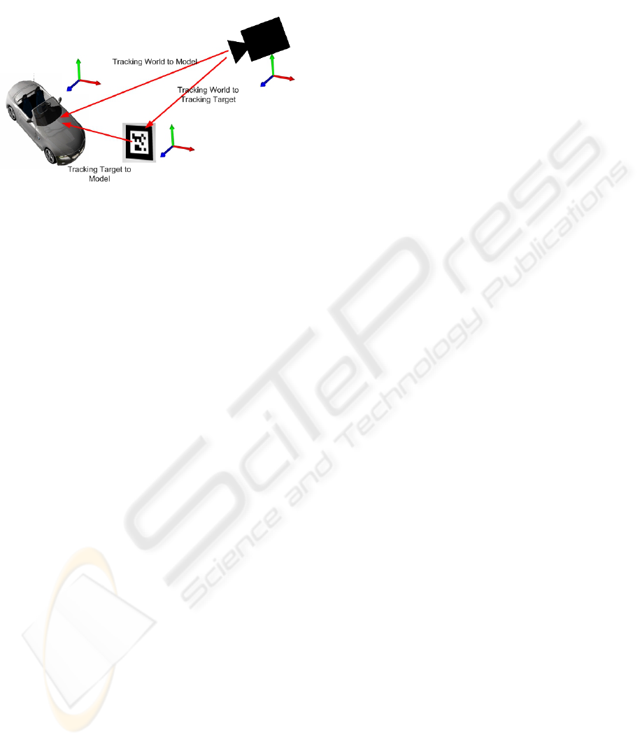
offset from the target coordinate system to the model
coordinate system.
Figure 1: Coordinate systems in an industrial AR environ-
ment.
1.2 Support for Industrial Registration
Motivated by these needs, this work presents differ-
ent tools for supporting industrial registration. The
following approaches for the determination of the ref-
erence offset are described:
• Referencing using an external coordinate mea-
surement machine (CMM): The most reliable ref-
erencing process requires a CMM at hand.
• Referencing using 3D-3D correspondences:
Given tracking data and CAD data, manu-
ally defined correspondences can be used for
referencing.
• Referencing using 2D-3D correspondences: In
this case, image data and CAD data are combined
to do the referencing process.
• Referencing using digital data manipulation
(CAD-based): Finally, the referencing process
can be bypassed by bringing model and tracking
target coordinate system into accordance.
The different approaches shall be evaluated
according to their usability and accuracy. This
evaluation process is currently undertaken and its
results will support the choice of referencing tools for
concrete application scenarios. Usability is measured
in terms of needed input data, needed knowledge for
performing the registration and time consumption of
the task. For accuracy evaluation, an estimate for the
resulting pose accuracy shall be determined based on
the underlying calculations.
2 RELATED WORK
Registration and registration error analysis have been
subject to many publications in the area of Aug-
mented Reality. A comprehensive overview on reg-
istration error analysis is given in (Holloway, 1997).
Here, Holloway states tracking, calibration and mod-
eling as main sources of registration error. Based
on these sources of error, research has been done
to improve or analyze registration accuracy in terms
of tracking systems (Hoff and Tyrone, 2000), (Davis
et al., 2003), calibration methods (Gibson et al.,
2002), (Vigueras Gomez et al., 2005) or complete AR
systems (Kato and Billinghurst, 1999).
This work covers another aspect of registration,
needed besides good tracking and calibration, when
the tracking target cannot be placed at the desired lo-
cation: the determination of a referencing offset, as
described above (see figure 1).
In their work on the integration of Augmented Reality
in the assembly domain, Reinhart et al. mention the
importance of referencing, that is the determination of
the relative position of displayed objects to known ref-
erence marks (Reinhart and Patron, 2003). Another
example of referencing problems is given in (Appel,
2003). The author states the great effort which is
needed to reference markers (of a marker based opti-
cal tracking system) in the spacious environment and
to place them at the needed positions.
In the following sections, this problem shall be
met by presenting several approaches for industrial
referencing.
3 APPROACHES FOR
REGISTRATION
In the context of an AR application for factory
planning, several approaches for registration were
developed. The application itself is described in
detail in (Pentenrieder et al., 2007). 3D digital
planning data is augmented onto high-resolution
2D images of the real factory to offer possibilities
for AR-based factory planning in terms of distance
measurements, collision detections or variance
comparisons. Tracking is realized through an optical
marker-based tracking.
Depending on the type of application and the
available resources, it is necessary to calculate an
additional referencing offset as described above. The
following possibilities for referencing are available:
REGISTRATION APPROACHES FOR AUGMENTED REALITY - A Crucial Aspect for Successful Industrial
Application
427
3.1 Referencing using an External
Coordinate Measurement Machine
With an external coordinate measurement machine
(CMM), the referencing process can be achieved by
using the referencing functionalities of the CMM.
CMMs provide high-precision measurements based
on a measuring probe. They are equipped with a mea-
suring software, that allows to transform the internal
origin coordinate system to an arbitrary location us-
ing point correspondences.
Using CMM referencing in the context of AR-based
factory planning, requires a CMM which is already
referenced to the model coordinate system (e.g. the
car body coordinate system). This can be achieved
using the CMM measuring software. Then, 3D point
correspondences between tracking target coordinate
system and model coordinate system are used to de-
termine the needed offset. Figure 2 shows an excerpt
of the tool for CMM referencing. The user needs
to specify the four marker corner points of a paper
marker (tracking target) in the CMM coordinate sys-
tem (model coordinate system). Based on these four
points the transformation between the marker coordi-
nate system and the model coordinate system is cal-
culated, by setting up the transformation matrix using
the point coordinate vectors.
u
x
v
x
w
x
c
x
u
y
v
y
w
y
c
y
u
z
v
z
w
z
c
z
0 0 0 1
−1
with u =
−−−→
P1P4,
v =
−−−→
P1P2
and w = u × v
For our marker tracking, the origin lies in the cen-
ter of the marker (c = (P1 + P2 + P3 + P4)/4). The
coordinate axes are indicated in figure 2, z pointing to
the observer.
In addition, an accuracy value for the corner point
accuracy can be specified which is then used to esti-
mate the accuracy of the resulting transformation (po-
sitional and rotational accuracy), see section 4.
Figure 2: CMM referencing.
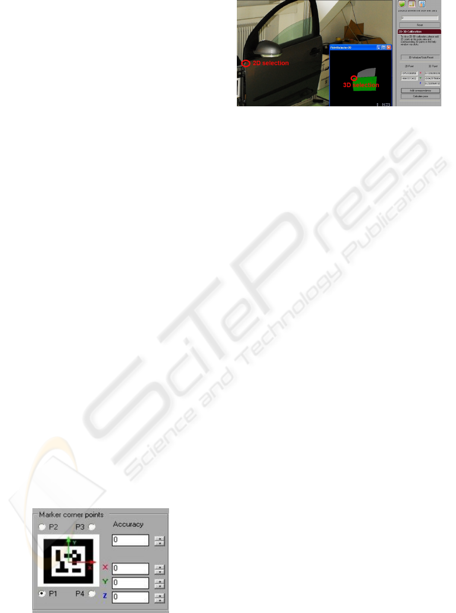
Figure 3: Referencing using 2D-3D point correspondences.
3.2 Referencing using 2D-3D
Correspondences
The next option for referencing is based on 2D-3D
point correspondences which are provided by the user
through clicks. The tool requires image data and cor-
responding 3D digital data. Figure 3 presents the tool
in usage. 2D points are selected in the image of the
scene and 3D points are chosen in a viewer show-
ing the corresponding digital model. The point cor-
respondences are sent to a camera pose estimation al-
gorithm, that calculates the transformation from the
camera coordinate system (in our case this is the
tracking world coordinate system) to the model co-
ordinate system.
3.3 Referencing using 3D-3D
Correspondences
When information on specific points in the 3D model
is available, 3D-3D correspondences can be used for
referencing. In this case, selected locations are used
which are known in the 3D digital model and can
be tracked easily in the real environment. An ex-
ample from industry are specific drill-holes which
are calibrated precisely when the object is manufac-
tured. These holes are known exactly in the digital
data. Their real counterparts can be tracked by us-
ing adapters, that fix the tracking target to the calibra-
tion point (e.g. drill hole). Figure 4 depicts a marker
equipped with an adapter to fit the drill holes of an
align fixture. The 3D-3D referencing tool uses shots
of a scene featuring adapter markers for selected cali-
bration points and a list of corresponding digital 3D
coordinates to estimate the transformation between
camera (tracking world) coordinate system and model
coordinate system. Given this transformation, the off-
sets from each marker (tracking target) to the model
coordinate system can be calculated, referencing thus
each single marker to the model coordinate system.
For optimization purposes, the tool first optimizes the
GRAPP 2008 - International Conference on Computer Graphics Theory and Applications
428
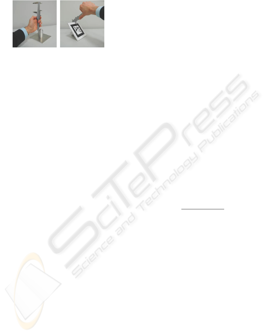
Figure 4: Adapter for 3D-3D referencing.
offsets between all available markers over all given
images and then performs the referencing step to the
model coordinate system. That way, the resulting
transformation is optimized with respect to the given
images and offers thus optimal conditions for later
planning and analysing tasks based on the same im-
age data.
3.4 Referencing using a CAD-based
Approach
The last approach requires some knowledge in the
CAD environment. Here, the digital model itself is
manipulated to fit better the requirements for its usage
in the AR scenario. A favorable location in the real
environment is chosen which can be easily retrieved
in the digital representation, for instance a drill-hole.
The tracking target is placed at the chosen location in
the real world. Then, a CAD tool is needed to move
the coordinate system of the digital model from its
current position to the location chosen for the tracking
target in the real environment. That way, the transfor-
mation from the tracking target coordinate system to
the model coordinate system does no longer require
a translation, as their origins are identical. To com-
pensate for the rotational discrepancy, the model is
loaded in the factory planning environment and rota-
tion changes around the different axes are performed
with sub-degree precision, until optimal visual con-
sistency is achieved.
4 EVALUATION APPROACH
The referencing toolbox shall be evaluated with re-
spect to accuracy and usability criteria. As this work
is in progress, this section presents the current state of
our analysis.
4.1 Accuracy Evaluation
For the evaluation of accuracy, some assumptions on
the input accuracy are needed which can then be used
to calculate an accuracy statement for the resulting
translation and rotation. The next paragraphs de-
scribes the basic work which has already been done in
order to prepare for a comprehensive accuracy study.
CMM Referencing. When a CMM is used for ref-
erencing, the input accuracy is provided by the posi-
tional accuracy of the CMM which is usually stated
in the machine specification. Given this value, the
resulting transformation accuracy can be calculated
using backward error propagation (see for instance
(Hartley and Zisserman, 2003)).
The base formula for backward propagation is given
by
[R|t] ·q
k
= p
k
⇒ [R|t]· q
k
− p
k
= 0
where [R|t] denotes a 4 × 4 transformation matrix
based on rotations around the three axes r
x
,r
y
,r
z
and
a three-dimensional translation (t
x
,t
y
,t
z
), p
k
are the
measured points in the CMM coordinate system and
q
k
are the corresponding points in the marker (target)
coordinate system.
For the calculation, three point correspondences are
needed which form the matrix
F =
[R|t] · q
1
− p
1
[R|t] · q
2
− p
2
[R|t] · q
3
− p
3
= 0
The Jacobian matrix which represent the uncertainty
is then given by
J
F
=
δF(q
k
, p
k
)
δ(t
x
,t
y
,t
z
,r
x
,r
y
,r
z
)
This calculation process is integrated in the tool de-
picted in figure 2. Concrete accuracy values can be
calculated by entering a positional accuracy for the
used coordinate measurement machine together with
the determined 3D points.
2D-3D Referencing. For 2D-3D referencing the in-
put accuracy is the accuracy with which the user can
click a specific point in an image and on a 3D digi-
tal model. To determine this click accuracy tests were
performed using our marker tracking as basis. The
participants were asked to click on three example im-
ages of a paper marker (1: camera image 640x480
pixel, 2: camera image 3008x2000 pixel, 3: simu-
lated image 3008x2000) of different quality and se-
lect a specific corner point within the environment of
the 2D-3D referencing tool. For image 1 and 2 the
results were compared with the respective corners de-
tection results of our marker tracking algorithm, for
image 3 the real values were known due to simulation.
The results of this study (average euclidean distance
and standard deviation in pixel) are shown in figure
REGISTRATION APPROACHES FOR AUGMENTED REALITY - A Crucial Aspect for Successful Industrial
Application
429
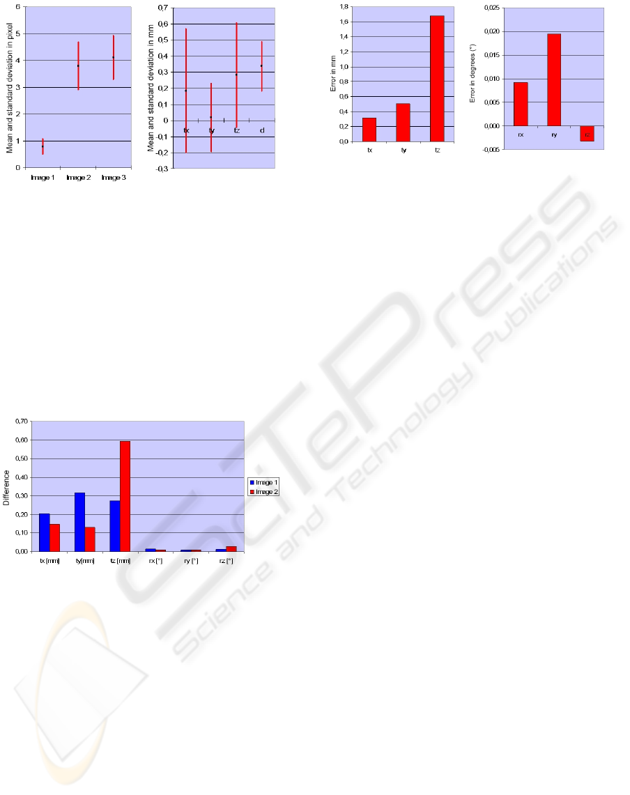
Figure 5: Results of the click tests: (a) 2D case (b) 3D case.
5 (a). A similar test was performed for the 3D case,
whose results are visualized in figure 5 (b) (mean er-
ror and standard deviation in 3D and for the euclidean
distance). In a second step, the detected errors and
standard deviations were used to add Gaussian noise
to the correct marker corners and compare the noisy
pose results with the correct ones. Figure 6 presents
those results for the low (image 1) and the high reso-
lution case (image 2). User clicks can thus compete
very well with image based corner detection.
Figure 6: Differences in translation and rotation for the im-
ages.
3D-3D Referencing. For the 3D-3D referencing
case we consider the 3D model data to be perfect.
Thus, the optimization depends on the quality of
the adapter and on the marker tracking determining
the location of the marker. Figure 7 shows a pose
error calculation for a representative 3D-3D refer-
encing scene based on the accuracy information de-
termined for our marker tracking (see (Pentenrieder
et al., 2006) ).
CAD Referencing. For the CAD approach it is dif-
ficult to create an accuracy statement. The output
again depends on the quality of the target adapter
and the tracking. The position is then fixed manu-
ally through coordinate system movement. Due to
Figure 7: Pose error for 3D-3D referencing.
CAD scaling and the selection of favorable points the
re-positioning of the coordinate system can be done
with model accuracy, meaning with the accuracy of
the model tessellation (polygonal representation of
the real object). The rotation is adapted manually. In
case a 0.1
◦
step size is taken, the maximum accuracy
achievable is in this range.
4.2 Usability Evaluation
For the usability evaluation the following criteria are
regarded: input requirements, needed knowledge to
perform the referencing process and output informa-
tion.
CMM Referencing. CMM referencing requires
knowledge about the usage of the CMM and its mea-
suring software. Thus a skilled person needs to do the
task, providing CMM point coordinates as input for
the referencing tool. The output consists of a trans-
formation from the marker coordinate system to the
CMM coordinate system and a corresponding accu-
racy value for the calculation.
2D-3D Referencing. 2D-3D referencing is proba-
bly the easiest way of creating a reference offset.
Corresponding image and model data needs to be
available. By simple clicks, the user identifies cor-
respondences between 2D and 3D world. The result
is given as a transformation from the camera to the
model coordinate system. Different from the other
approaches, here no intermediate marker coordinate
system is needed.
Still, it is important to have image data available
where correspondences can be identified easily.
3D-3D Referencing. 3D-3D referencing requires a
set of images which show markers attached to se-
lected locations of an object, that are also known in
GRAPP 2008 - International Conference on Computer Graphics Theory and Applications
430

the digital world. The tool then calculates the ref-
erencing offsets based on this input data. However,
the crucial aspect is the acquisition of this data, hence
the positioning of the markers using adapters and the
identification of the corresponding CAD point infor-
mation. For special locations (e.g. drill holes) this
digital data might already be given and adapters for
such holes need to be manufactured once and can then
be reused.
As the referencing offset is optimized over all mark-
ers and over all images, the outcome is favorable for
analysis with the given image set.
CAD Referencing. Similar to the CMM referenc-
ing, the CAD-based approach requires a skilled per-
son who is able to manipulate the given digital model
data, such as moving the model coordinate system to
a specific location. Furthermore, the marker needs to
be placed at the corresponding location of the real ob-
ject, similar to the 3D-3D case. Then, the manipu-
lated model needs to be superimposed onto an image
of the real scene with the marker in place to optimize
the orientation of the model using manual adjustment.
Next to CAD knowledge, this approach therefore also
requires experience in manual adjustment.
5 CONCLUSIONS AND
OUTLOOK
Accurate registration of real and virtual data is
crucial for many Augmented Reality application. In
industrial environments, specific data, knowledge
and systems are available which can support the
registration process. Still, available resources differ
from application to application. It is therefore
necessary to provide the users with a comprehensive
toolbox of different referencing methods, offering the
flexibility to choose the referencing approach suiting
best the given application.
We created a toolbox of various referencing
methods and are currently evaluating the different ap-
proaches with respect to accuracy and usability. Our
first studies show, that each tool has its advantages
and disadvantages. Based on these first results, we
will further evaluate the different approaches using
industrial scenarios in factory planning. The concrete
application of all approaches to the same scenario
will allow an absolute comparison and actual user
feedback will help us to verify the current implemen-
tations and gain experience for improvements and
extensions.
ACKNOWLEDGEMENTS
Part of this work was funded by the EU Project DiFac
(FP6-2005-IST-5No.035079).
We thank Volkswagen Group Research for their
continuous collaboration and valuable support in the
field of AR-based factory planning.
REFERENCES
Appel, M. (2003). Augmented reality f
¨
ur innovative
service- und engineering l
¨
osungen im kraftwerksbere-
ich. In 3. ARVIKA-Forum.
Davis, L., Clarkson, E., and Rolland, J. (2003). Predicting
accuracy in pose estimation for marker-based track-
ing. In Second IEEE and ACM International Sympo-
sium on Mixed and Augmented Reality ISMAR.
Gibson, S., Cook, J., Howard, T., Hubbold, R., and Oram,
D. (2002). Accurate camera calibration for off-line,
video-based augmented reality. In International Sym-
posium on Mixed and Augmented Reality (ISMAR),
pages 37–46.
Hartley, R. and Zisserman, A. (2003). Multiple View Geom-
etry. Cambridge University Press.
Hoff, W. and Tyrone, V. (2000). Analysis of head pose ac-
curacy in augmented reality. In IEEE Transactions on
Visualization and Computer Graphics, volume 6.
Holloway, R. (1997). Registration error analysis for aug-
mented reality. In Presense: Teleoperators and Virtual
Environments, pages 413–432.
Kato, H. and Billinghurst, M. (1999). Marker tracking and
hmd calibration for a video-based augmentedreality
conferencing system. In Second IEEE and ACM In-
ternational Workshop on Augmented Reality (IWAR),
pages 85–94.
Pentenrieder, K., Bade, C., Doil, F., and Meier, P. (2007).
Augmented reality - based factory planning - an appli-
cation tailored to industrial needs. In Sixth IEEE and
ACM International Symposium on Mixed and Aug-
mented Reality (ISMAR).
Pentenrieder, K., Meier, P., and Klinker, G. (2006). Anal-
ysis of tracking accuracy for single-camera square-
marker-based tracking. In Dritter Workshop Virtuelle
und Erweiterte Realitaet der GI-Fachgruppe VR/AR.
Regenbrecht, H. (2006). Emerging Technologies of Aug-
mented Reality: Interfaces & Design, chapter In-
dustrial Augmented Reality Applications, pages 283–
304. Idea Group Publishers.
Reinhart, G. and Patron, C. (2003). Integrating augmented
reality in the assembly domain - fundamentals, bene-
fits and applications. ANNALS-CIRP, 52(1):5–8.
Vigueras Gomez, J.-F., Simon, G., and Berger, M.-O.
(2005). Calibration errors in augmented reality: a
practical study. In Fourth International Symposium on
Mixed and Augmented Reality (ISMAR), pages 154–
163.
REGISTRATION APPROACHES FOR AUGMENTED REALITY - A Crucial Aspect for Successful Industrial
Application
431
