
HAPCO: REAL TIME SIMULATION OF INTERACTION
BETWEEN DEFORMABLE OBJECTS WITH HAPTIC
FEEDBACK FOR SOLVING FRICTION MULTIPLE CONTACTS
Nadjet Talbi, Pierre Joli
Laboratory IBISC, Evry Val d’Essonne university, 40 rue de Pelvoux, 91020 Evry, France
Zhi-Qiang Feng
Laboratory LME, Evry Val d’EssonneUniversity, 40 Rue de Pelvoux, 91020 Evry, France
Abderrahmane Kheddar
Laboratory JRL, AIST Tsukuba Central 2, Umezono 1-1-1, Tsukuba 305-8568, Japan
Keywords: Friction Contact, Interactive Simulation, Haptic rendering, Uzawa technic, Bi-potential Method.
Abstract: This paper deals principally with the comparison of two efficient algorithms to solve multi-contact problems
with friction between two deformable bodies. These two algorithms are based on the bi-potential
formulation of the contact laws, offering the control of the solution at each contact point through an unique
mathematical operator of projection as well as a better force feedback stability of the friction contact force.
For reasons of modular programming, a method to decouple the contact solver from the displacement
solver is presented. A Haptic Contact simulator called “HapCo” has been developed as a prototype to test
contact algorithms between two deformable objects in the context of interactive simulation with a haptic
device.
1 INTRODUCTION
During the last twenty years, technologies related to
medical areas have enormously improved; one of
them is medical interactive simulators. The interest
of interactive simulators based on advanced virtual
and augmented reality techniques comes mainly
from the surgeon’s needs in terms of advanced
teaching and training tools. Virtual Reality has been
developed for many years in this context to reduce
learning problems. The interactive simulation
associated with multimodal rendering (haptic, visual,
touch …) provides medical operators the possibility
to learn faster and easier. Surgical simulators are
currently being developed at many research centers
and companies (Gibson et al., 1997), (Cotin et al.,
2000) , (Zhuang, 2000) to create environments to
help train physicians in the use of new surgical
instruments and techniques in minimally invasive
surgery. In this type of application, the numerical
context is soft body simulation based on physical
models. Because surgical instruments are typically
long slender structures, the contact points are limited
to one point (point-based rendering) or some points
along a segment (ray-based rendering) but never on
a surface (surface-based rendering). However it
could be interesting to consider for example the
shape of a new surgical tool to test its efficiency in
surgical tasks such as pulling, clamping, gripping
and cutting soft tissue. Multiple contact points could
be considered in that case between a rigid body (the
tool) and the deformable object (the tissue). But in
all complex simulated surgical tasks, we have to
consider the organ-organ interaction through a
surfaced distribution of contact points between two
deformable bodies. In such a medical context of
simulation, there is an ongoing quest for faster
algorithms to solve multiple contact forces while
controlling the numerical stability of the solution.
A real time simulation relies on three optimized
55
Talbi N., Joli P., Feng Z. and Kheddar A. (2008).
HAPCO: REAL TIME SIMULATION OF INTERACTION BETWEEN DEFORMABLE OBJECTS WITH HAPTIC FEEDBACK FOR SOLVING FRICTION
MULTIPLE CONTACTS.
In Proceedings of the Third International Conference on Computer Graphics Theory and Applications, pages 55-61
DOI: 10.5220/0001095900550061
Copyright
c
SciTePress
numerical “black boxes”, the first one to detect the
potential contact points (collision detector), the
second one to solve the nodal displacements of the
discrete objects (displacement solver) and the third
one to solve the multiple friction contact forces
(contact solver). This paper concerns only
descriptions about the contact solver. Interested
readers may refer to (Teschner et al., 2004), (Lin,
1998) for a review of collision detectors and to
(Erleben et al., 2005), (Gibson, 1997) about physics-
based displacement solvers.
In the next section, we present a Haptic
Contact simulator called “HapCo” developed in our
laboratory as a prototype to test contact algorithms
between two deformable objects in the context of
interactive simulation with a haptic device. The
important concept of the flexibility method is
presented in which there is a separation between the
computation of the contact forces and the
computation of the nodal displacements.
The third section presents the formulation and
the resolution of friction contact problems and it is
focus on two efficient algorithms for the contact
solver, called respectively “local Uzawa” and
“global Uzawa”. They are both based on a
bipotential formulation introduced by De Saxcé and
Feng (De Saxce, 1991), (Feng, 1995). This
formulation has the advantage to control the solution
of the friction contact force. Finally we report and
discuss the experimental results followed by some
perspectives of future works.
2 DESCRPTION OF THE
“HAPCO” SIMULATOR
The Haptic Contact “HapCo” simulator is a
prototype developed in our laboratory to test contact
algorithms between two deformable bodies in the
context of interactive simulation with a haptic
device. These two bodies are parallelepiped (see
figure 5), The red one can be clamped at its
extremities and the green one can be manipulated in
translation by the operator through a PHANTOM
Desktop haptic interface (Sensable).
In the HapCo simulator, we use a linear elastic
modelling of the bodies based on the Finite Element
Method (FEM). We consider only quasi-static
analysis because of very small inertial forces in
medical applications. The linear elastic modeling is
not really justified because it is only accurate for
small deformations which is not the case of soft
tissues (hyperelastic deformations). We have chosen
the linear modeling only for reasons of simplicity
and computational efficiency. It is important to
announce that our friction contact solver is suitable
either for the non linear modeling or any other
deformation modeling since it is based on the
principle of flexibility (Francavilla, 1975) which
allows to decouple the numerical task of the
displacement solver from the numerical task of the
friction contact force solver.
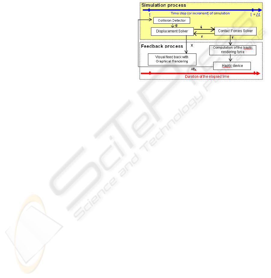
Figure 1: Data flow chart of the HapCo simulator.
The figure 1 describes the functional diagram
of the interactive simulation in “HapCo”. When a
collision is detected between the green body and the
red one (see figure 5), the displacement solver
computes the relative free displacement between
the potential pairs of contact points. Then the contact
solver gives the local contact forces r in order to
avoid any interpenetration (Signorini condition) and
to satisfy Coulomb laws (stick/slip phenomena).
Finally the displacement solver computes all
the nodal positions of the two bodies by
considering the contact forces as external (or given
forces). The haptic rendering force is then computed
from the given contact forces and sent back to the
operator.
So this feedback force takes into account the
stiffnness of the two bodies and the friction contact
laws (Signorini and Coulomb) of all contact points
distributed on the contact surface. The next step of
the simulation process is reinitialised from the new
increment of rigid displacement given by the
operator through the haptic device. The sample
frequency of the elapsed time must be superior to 25
Hz to have an accurate visual rendering and superior
to 300 Hz to have an accurate haptic force rendering.
view). The main objective of HapCo is to test
different algorithms to solve multi friction contact
problem in order to determinate witch one gives the
best stable force feedback in real-time.
GRAPP 2008 - International Conference on Computer Graphics Theory and Applications
56
3 ALGORITHMIC PRINCIPLE
We propose to follow an incremental mixed
formulation (displacement and contact force) of the
equilibrium equations and to solve separately the
contact force by successive local projections of these
equations in the local reference frames at contact
points. This method is called the flexibility method
because it consists of establishing a flexibility matrix
(Francavilla, 1975) or a Delassus operator (Duriez,
2005).
In order to calculate the friction contact forces,
the contact laws (Signorini and Coulomb) are
formulated from an augmented Lagrangian
formulation (bi-potential formulation) and computed
by an Uzawa technique which leads to an iterative
predictor/corrector process. The bipotential method
proposed by De Saxcé and Feng (Feng, 2003),
(Feng, 1995) provides a powerful tool to model
dissipative constitutive laws such as Coulomb
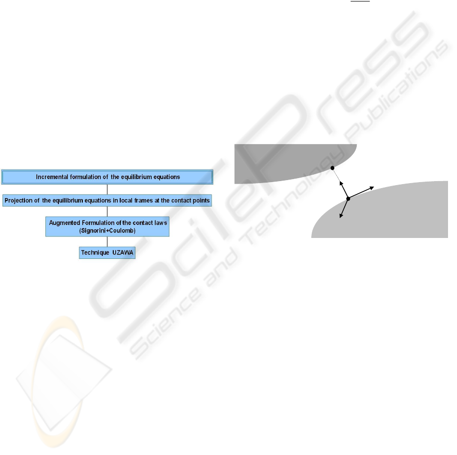
friction laws. The figure 2 describes the basic
principle of this method. Interested readers can find
more details in (De Saxcé, 1991 and Wriggers,
2002).
Figure 2: Principle Algorithm.
3.1 Incremental Formulation of
Equilibrium Equations
The following equation governs the quasi static
nonlinear problems involving contact between finite
element bodies:
F
int
+ F
ext
+ R =0
where F
int
is the vector of internal nodal forces,
F
ext
denotes the vector of external nodal forces and
R, the vector of nodal contact forces.
This equation is strongly nonlinear with respect
to the nodal displacements U, because of finite
strains and large displacements. The incremental
formulation consists of writing a linear relation of
the internal forces relative to U. A Newton-Raphson
iterative resolution is carried out as follows:
⎧
⎪
⎨
⎪
⎩
ii i
Tintext
i+1 i
K ∆U=F +F +R
U=U+∆U
where i is the iteration number at which the
equations are computed.
i
T
K is the tangent stiffness
matrix and ∆U is the correction vector of the nodal
displacements. Taking the derivative of F
int
with
respect to U gives the tangent stiffness matrix:
int
∂
=−
∂
T
F
K
U
It is noted that the incremental formulation of
the equilibrium equations can not be solved directly
since ∆U and R are both unknown. The key idea is
to determine first R in a reduced system which only
concerns the contact nodes. Then ∆U can be
computed in the whole structure, using contact
reactions as external forces. In the following section,
we describe how to determine the contact forces.
3.2 Friction Contact Formulation
Figure 3: Local coordinate frame at the contact point
α
.
The unilateral contact law in the case of
deformable objects is characterized by a linear
relationship between the constraint displacement
α
u
and the contact force
α
r, for each pair of contact
points
α
= (1..m) as shown in figure 3. This relation
can be written as:
ααβ α α
αα
+Wr+uu=u
where W
αα
and
α
u
represent respectively the
local flexibility matrix (3x3dimension) and the free
displacement at the contact point α (i.e. when all the
contact forces are zero).
αβ
u is the displacement at
the contact point α induced by the contact forces
occurring at contact points α≠β.
α
u,
αβ
u and
α
r are
defined relative to the local coordinate frame
positioned at the contact point
α
. The flexibility
matrix depends on the local stiffness of each object
in contact and the free displacement depends on the
internal forces and the external forces applied to
Ω
1
Ω
2
P
α
P’
α
n
t
1
t
2
u
n
HAPCO: REAL TIME SIMULATION OF INTERACTION BETWEEN DEFORMABLE OBJECTS WITH HAPTIC
FEEDBACK FOR SOLVING FRICTION MULTIPLE CONTACTS
57
each object in contact.
This equation represents a system of 3 scalar
equations where the local unknowns are
α
u and
α
r
(6 scalar unknowns). To describe the local behavior
of each contact point
α
additive constraints are
necessary.
The unilateral contact law is characterized by a
geometric condition of non-penetration, a static
condition of no-adhesion and a mechanical
complementary condition. These three conditions
are known as Signorini conditions expressed, for
each contact point
α
, in terms of the normal signed
constrained displacement
α
u
n
=
α
u.n and the normal
signed contact force
α
r
n
=
α
r.n by:
Signor( , ) 0, 0 and ( ) 0
nn n n nn
ur u r ur
αα α α αα
⇔≥ ≥ =
The classical Coulomb friction rule is defined by:
Coul( , ) If 0 then
else
tt t t n
t
t
t
r
α
αα αα
α
α
α
µ
µ
⇔= ≤
=−
ur u r
u
r
u
Where
µ
is the coefficient of friction and
α
u
t
(resp.
α
r
t
) is the tangential part of
α
u (resp.
α
r).
The complete contact laws (Signorini condition
+ Coulomb friction laws) can be defined by the three
contact states as follows:
•
0and 0
nn
ur
αα
>=
(Separating)
•
0
and int ( )
t
t
K
α
α
α
µ
⎧
=
⎪
⎨
⎪
∈
⎩
u
r
(Contact with sticking)
•
0
and bd ( )
with
t
t
t
tn
t
K
r
α
αα
µ
α
αα
α
µ
⎧
⎪
≠
⎪
⎪
⎪
∈
⎨
⎪
⎪
=−
⎪
⎪
⎩
u
r
u
r
u
(Contact with sliding)
Where
K
α
µ
is the so-called Coulomb cone at
the contact point
α
and represents the set of
admissible forces defined by:
{
}
3
tel que 0 et 0
ntn
KRr r
αα α α α
µ
µ
=∈ ≥ − ≤rr
The terms
int( )K
α
µ
and
b
d ( )K
α
µ
are respectively
the interior and the surface of the Coulomb cone.
The contact laws give no explicit relation between
α
r
t
and
α
u
t
in case of contact with sticking and in
case of no contact.
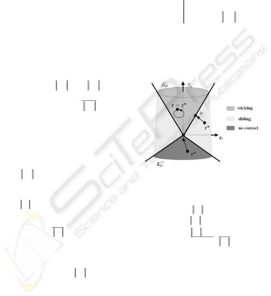
Based on the augmented lagrangian method
used to solve contact problems (Alart, 1991 and
Simo, 1992), De Saxcé and Feng have proposed to
use the bi-potential formulation to write the
complete contact laws by the following projection
operator:
*
**
*
Proj ( )
with
K
t
µ
αα
αα α
αα α
ρ
µ
=
=−
=+
rr
rr u
uu un
Where
α
r
*
is the so-called augmented contact force
at the contact point
α
.
Proj
K
µ
is the projection
operator on the Coulomb cone.
ρ
is an arbitrary
positive parameter. The three possible contact states
are illustrated in figure 4.
Figure 4: Coulomb cone projection and contact states.
Within the bi-potential framework, the
projection operation can be explicitly defined by:
** **
***
**
*
**
2
*
Proj ( ) = si Sticking
Proj ( ) = 0 si No Contact
Proj ( ) = liding
1
Ktn
Ktn
tn
t
K
t
r
r
r
S
µ
µ
µ
αα α
αα
α
α
αα
α
µ
µ
µ
µ
µ
≤
≤−
⎛⎞⎛⎞
−
⎜⎟⎜⎟
−−
⎜⎟⎜⎟
+
⎜⎟⎜⎟
⎝⎠⎝⎠
rr r
rr
r
r
rr n
r
3.3 Friction Contact Resolution
From the above equations and by considering m
contact points, we have to solve successively m local
systems (
α
=1, m) described as:
*
0
Proj ( ) 0
K
µ
αααβα
αα
αα
⎧
−
−−=
⎪
⎨
−=
⎪
⎩
uW r u u
rr
These m local systems are implicitly dependent
GRAPP 2008 - International Conference on Computer Graphics Theory and Applications
58
because of
αβ
u which has the following expression:
1,m
αβ β
αβ
β
αβ
=
≠
=
∑
uWr
Where each W
αβ
can be considered as an
influence matrix between two contact points
α
and
β
. To solve these local systems, we propose the two
following approaches:
3.3.1 Local Uzawa Approach
The non linear iterative Gauss Seidel algorithm
consists of solving successively the m local systems
at each iteration k:
(1) (1) (1)
(1) (1)*
(1) (1) ()
1, 1 1,
0
Proj ( ) 0
kkk
kk
K
kk k
m
µ
αααβα
αα
αα
αβ β β
αβ αβ
βα βα
+++
++
++
=− =+
⎧
−−−=
⎪
⎨
−=
⎪
⎩
=+
∑∑
uWr uu
rr
uWr Wr
Until we obtain the numerical convergence defined
by:
( 1) () () 1() ()
1
( ,...., )
kk kkmk
rr
ε
+
−< =rr r
where
ε
1
is the numerical tolerance of the global
contact force which can be related to the precision of
the haptic device. The initial value is
(0)
0=r .
Now we have to solve for each local system the
unknowns
(1)k
α
+
u
and
(1)k
α
+
r
. The numerical
solution can be carried out by means of the Uzawa
algorithm which leads thus to an iterative process:
(1)()
*( 1)( 1) ( 1)( ) ( 1)( )
(1)(1) *(1)(1)
(1)(1) (1)(1) (1)
()
Proj ( )
kj
kj kj kj
t
kj kj
K
kj kj k
µ
αααα
αα
αααβα
αα
ρµ
+
++ + +
++ ++
++ ++ +
=− +
=
=++
rruun
rr
uWr uu
The numerical convergence is given by:
( 1)( 1) ( 1)( )
2
kj kj
αα
ε
ρ
++ +
−
<
rr
ε
2
is a second numerical tolerance which can be
related to the desired visual rendering or to the
physical interpenetration tolerance which can be
estimated from characteristic lengths of the objects
in contact. The initial values are
(1)(0)
0
k
α
+
=
r and
(1)(0) (1)kk
α
αβ α
++
=+
uuu.
We call this approach the “local Uzawa”.
Indeed, the two presented iterative processes
compute all the contact forces with two levels of
control. One is local to each contact point and based
on visual rendering and the other is global and based
on the haptic rendering.
3.3.2 Global Uzawa Approach
Another way is to have a control only on the haptic
rendering by considering only one predictor
corrector step in the Uzawa algorithm:
• Predictor step:
()
*( 1) ( 1) ( )
()
k
kk k
t
αα αα
ρµ
++
=− +rr uun
• Corrector step
(1) *(1)
Proj ( )
kk
K
µ
αα
++
=rr
• Back up the new constrained displacement
(1) (1) (1)kkk
α
ααβ α
αα
+++
=++
uWr u u
We call this approach the “global Uzawa”.
Many examples have been successfully treated
(Feng, 1995 and 2003) with the global Uzawa
approach but only in a standard simulation process
(non interactive). In these examples the numerical
convergence is given by:
(1) ()
3
(1)
kk
k
ε
+
+
−
<
rr
r
In computational mechanics,
ε
3
is just a very
small parameter (relative error) related only to a
desire of a high numerical precision.
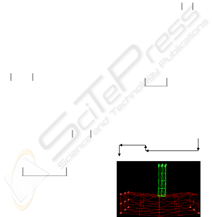
3.3.3 Comparison and Results
To compare the local and global Uzawa approaches,
we consider the following benchmark:
Figure 5: Numerical benchmark 1.
The highlighted points on the upper surface of
5 P
20 P
7 P
4 P
1 P
HAPCO: REAL TIME SIMULATION OF INTERACTION BETWEEN DEFORMABLE OBJECTS WITH HAPTIC
FEEDBACK FOR SOLVING FRICTION MULTIPLE CONTACTS
59
the green object move along 5 series of rigid
displacements as described in figure 5. Every unit
displacement P is equal to 0.1cm. The red object is
clamped on its extremities at the highlighted nodal
points (see figure 6). The green object and the red
one have respectively 80 000 and 3000 as Young
modulus. Both objects have the same Poisson ratio
equal to 0,3. The dimensions of the clamped elastic
solid are L=10, W=2, H=2 (cm). Initially, the two
objects are not deformed and are in contact (no
interpenetration). The computer used is a Pentium 4
with 1.75 Ghz and 1.5 Go of RAM.
Simulation results are shown in figures 7 and 8.
In the second numerical benchmark, the red object is
fixed from only the left extremity. That makes this
benchmark less stiff than the previous one,
numerical results are shown in figure 9. For both
algorithms (local and global Uzawa), we choose to
control only the physical interpenetration tolerance,
then all the numerical convergence thresholds
1
ε
,
2
ε
and
3
ε
are defined by:
(1) ()
1
() 0,3
kk
ii
Uzawa Error Min i m
W
αα
ρ
ρ
+
−
<==
rr
ρ
is equivalent to a stiffness and must be inferior to
the smallest local stiffness at the contact points.
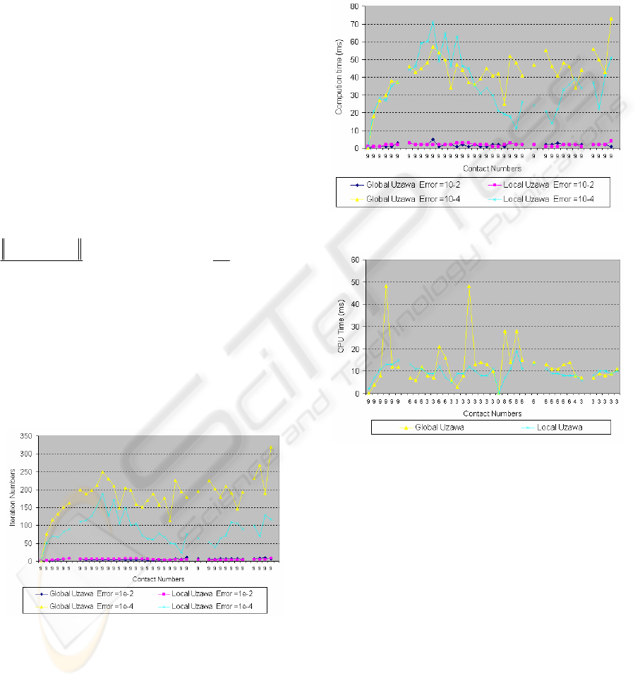
The figures 6, 7, and 8 are divided in 5 phases
according to the 5 rigid displacements series. We
note that the iteration numbers k in the local Uzawa
resolution are lower than the iteration numbers k
obtained for the Gauss-Seidel resolution in the five
simulation phases.
Figure 6: Friction coefficient = 0.3.
This result has been observed several times (as
shown in figure 7), for different values of the
friction coefficient (from 0.0 to 0.6) and for different
values of the Uzawa error. We observe from the
graph 8 that the Uzawa error has an important role
on the convergence time for the two resolution
techniques. Indeed, if the resolution precision
increases, then, the CPU time increases as well. This
result has been observed with many friction
coefficients. We can also note that local Uzawa
solver has a tendency to be faster than the global
Uzawa one. Figure 9 points out instabilities with the
global Uzawa solver.
Figure 7: Friction coefficient = 0.3.
Figure 8: Friction coefficient= 0.6, Uzawa Error =1e-4.
4 CONCLUSIONS
The HapCo simulator represents our first
contribution to bridge two domains, the
computational mechanics and the haptic rendering in
the context of Virtual Reality. This real time
simulator with haptic feedback force includes elastic
deformable objects, collision detection between
interacting bodies, friction contact force
computation and displacement solver based on the
Finite Element Method.
We have successfully tested the local and
global Uzawa algorithm described above with the bi-
potential approach. The results obtained seem to
indicate that the local Uzawa solver is faster and
GRAPP 2008 - International Conference on Computer Graphics Theory and Applications
60

more stable than the global Uzawa solver.
By changing the friction coefficient we can feel
the slip/stick contact force. Many people have tested
the HapCo simulator and have been surprised by the
quality of the haptic rendering.
We need more numerical tests to conclude
about the computational efficiency of the two
algorithms. Indeed, if the application works very
well when the moving object comes into contact
with the very soft parts of the clamped object, we
find some numerical instabilities when the contact
occurs with the stiff parts (near the fixed nodal
points). These difficulties have two origins. The first
one is when the operator does not handle firmly the
haptic device and can be surprised by the increase in
rigidity while he is moving towards rigid part. The
second one is due to excessive free displacement
α
u
when the contact occurs. The greater this quantity is,
the greater the number of iterations is and so the real
time constraint is no longer satisfied. To overcome
this difficulty, the operator has to move gently when
he comes into contact with the stiff parts. To help
the operator we suggest zooming around the contact
area in order to augment the control of his gesture by
a better visual feedback.
We are working to optimize and to accelerate
the simulation algorithm by considering closer the
sparseness of the matrices and vector manipulated
during the process. This is in order to consider non
linear elasticity modeling and large multi-contact
problems: childbirth simulation for example.
REFERENCES
De Saxcé, G., Feng Z.Q., 1998. “The bipotential method: a
constructive approach to design the complete contact
law with friction and improved numerical algorithms”.
Mathematical and Computer Modeling, special issue,
« Recent Advances in Contact Mechanics », 28(4–8),
225-245
.
Alart, P., Curnier, A., 1991. “A mixed formulation for
frictional contact problems prone to Newton like
solution methods”.
Comp. Meth. Appl. Mech. Engng.,
92, 353-375
.
Simo, J.C., Laursen, T.A., 1992. “An augmented
Lagrangian treatment of contact problems involving
friction”.
Computers & Structures, 42, 97-116.
De Saxce, G., Feng, Z.Q., 1991. “New inequality and
functional for contact with friction”: The implicit
standard material approach.
Mech. Struct. & Mach.,
19, 301-325
.
Feng, Z.Q., 1995. “2D or 3D frictional contact algorithms
and applications in a large deformation context”.
Comm. Numer. Meth. Engng., 11, 409-416.
Feng, Z.Q., Peyraut, F., Labed, N., 2003. “Solution of
large deformation contact problems with friction
between Blatz-Ko hyperelastic bodies”.
Int. J. Engng.
Science, 41, 2213-2225
.
Duriez, C., Dubois, F., Kheddar, A., Andriot, C., 2005.
“Realistic haptic rendering of interacting deformable
objects in virtual”.
IEEE trans. on visualization and
computer Graphics
.
Wriggers, P., 2002. “Computational contact mechanics”.
John Wiley & Sons.
Gibson, S.F.F., Mirtich, B., 1997. "A survey of
deformable modeling in computer graphics”.
Tech.
Report No. TR-97-19, Mitsubishi Electric Research
Lab, Cambridge, MA
.
Cotin, S., Delinggette, H., Ayache, N., 2000. "A hybrid
elastic model allowing real-time cutting, deformations,
and force feedback for surgery training and
simulation".
Visual Computer, vol. 16, no. 7, pp. 437-
452
.
Basdogan, G., De, S., Kim, J., Muniyandi, M., Kim, H.,
Srinivasan, M.A., 2004. "Haptics in minimally
invasive surgical simulation and training”.
IEE
Computer Society, Haptic Rendering-Beyond Visual
Computing, pp 56-64.
Zhuang, Y., Canny, J., 2000. “Haptic interaction with
global deformations”.
IEEE ICRA, San Francisco,
(pp20, 21, 88)
.
Francavilla, A., Zienkiewicz, O.C., 1975. “A note on
numerical computation of elastic contact problems”.
Int. Num. Meth. Eng. 9, 913-924.
Teschner, M., Kimmerle, S., Heidelberg, B., Zachmann,
G., Raghupathi, L., Fuhrmann, A.,. Cani, P, Faure, F.,
Magnenat-Thalmann, N., Strasser, W., Volino P.,
2004. Detection for deformable objects. Eurographics,
STAR (State of The Art Report), pp. 119-135..
Lin, M. C., Gottschalk, S., 1998. Collision Detection
between Geometric Models: A survey. Proc. of IMA
Conference on Mathematics of surfaces, pp. 37-56.
Erleben, K., Sporring, J., Henriksen, K., and Dohlmann,
H., 2005. Physics-Based Animation, Charles River
Media, Inc..
Gibson, S. F., Mirtich, B., 1997, A survey of deformable
modeling in computer graphics. Tech. Report No. TR-
97-19, Mitsubishi Electric Research Lab, Cambridge,
MA.
HAPCO: REAL TIME SIMULATION OF INTERACTION BETWEEN DEFORMABLE OBJECTS WITH HAPTIC
FEEDBACK FOR SOLVING FRICTION MULTIPLE CONTACTS
61
