
MAGNETIC COUPLING ANALYSIS OF A TET POWER
DELIVERY SYSTEM
Thushari Dissanayake, David Budgett
Bioengineering Institute,University of Auckland, 70 Symond Street, Auckland, New Zealand
Aiguo Patrick Hu
Department of Electrical and Computer Engineering,University of Auckland, 3 Grafton Road, Auckland, New Zealand
Keywords: TET, inductive power transfer, power efficiency, coupling coefficient, mutual inductance.
Abstract: This paper presents a comparative study of methods to determine the coupling coefficient between primary
and secondary coils used in a transcutaneous energy transfer system designed for powering implantable
biomedical devices. A coupling analysis covering typical misalignments between coils is presented using an
analytical model, a simulated model and practical experimental measurements. The simulated model shows
good agreement with the experimental measurements. The performance of the system is characterised by
carrying out a loss analysis to compute the power efficiency of the system for different misalignment
situations. It was established that variable coupling affects the maximum power transfer capacity but has a
low impact on the power efficiency for coil separations of less than 30mm.
1 INTRODUCTION
Many implantable biomedical devices require
electrical energy for operation. Two common
methods of supplying power are using an
implantable battery or by having a percutaneous lead
from the implant to an external power supply (N. de
N. Donaldson 1983). The downsides of these
methods are the limited life span of the battery and
the potential risk of infection associated with wires
through the skin. Inductively coupled power transfer
(ICPT) technology enables transfer of power across
the skin without direct electrical connectivity. This
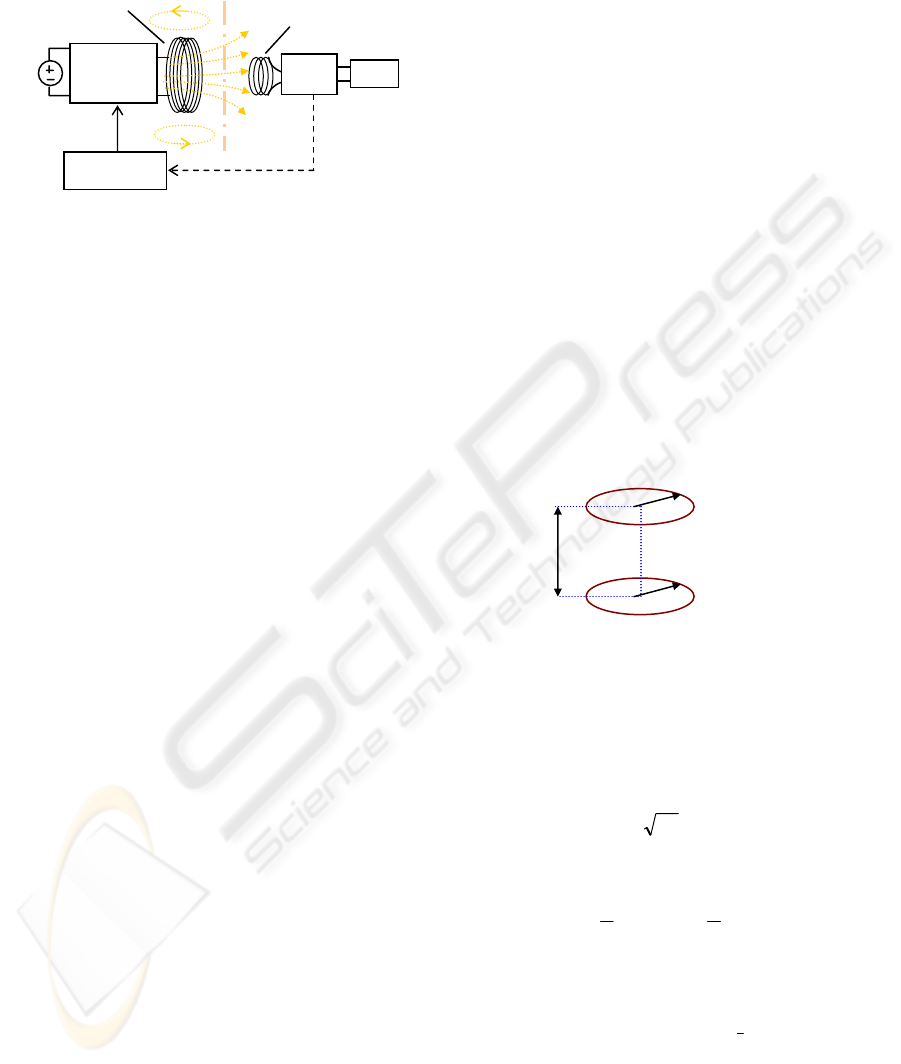
form of transcutaneous energy transfer (TET) is
illustrated in figure 1. The primary coil is located
outside the body and generates an electromagnetic
field. This time varying field penetrates the skin and
induces currents and voltages in the implanted
secondary coil which can be used to derive power
for the biomedical device.
In high power applications such as left
ventricular assist devices (LVADs), the TET coils
are located in areas of soft tissue where the coupling
conditions are highly variable. Normal patient
posture changes or differences in fitting the external
parts relative to the internal parts are likely to result
in changes to the alignment of the primary and the
secondary coils and their relative coupling (John C.
Schuder 1971). The coupling between two coils can
be represented by their mutual inductance. The
definition of mutual inductance is given by
Neumann’s double integral formula
∫∫
⋅
=
ij
jio
ij
R
dsds
M
π
μ
4
(1)
Where µ
o
is the permeability of free space, ds
i
and ds
j
are elements of two coils and R
ij
is the
magnitude of the distance from ds
i
to ds
j
. This
demonstrates that the mutual inductance is a
function of the coil geometries and the distance
between them (F.C Flack 1971). A more intuitive
representation of coil coupling is given by the
coupling coefficient, k, defined by:
21LL
M
k =
(2)
Where L
1
and L
2
are the self inductances of the
primary and the secondary coils respectively (C. M.
Zierhofer 1996). The coupling coefficient will equal
170
Dissanayake T., Budgett D. and Patrick Hu A. (2008).
MAGNETIC COUPLING ANALYSIS OF A TET POWER DELIVERY SYSTEM.
In Proceedings of the First International Conference on Biomedical Electronics and Devices, pages 170-175
DOI: 10.5220/0001051101700175
Copyright
c
SciTePress
1 for perfect coupling between two coils and zero for
no interaction.
Figure 1: Block diagram of a TET system.
Knowing the coupling coefficient between two
coils under a range of orientations is valuable for
accessing their ability to transfer sufficient power to
the load. This information can be used to guide the
design process for primary and secondary coils. The
coupling between primary and secondary coils has
been categorised into three components:
a) Separation: coils are axially aligned with a
separation gap (usually occupied by skin and
fat). For an abdominal TET site, this gap is
estimated to be within the range of 10 to 30mm.
b) Displacement: where the separation gap between
the coils is constant, but their centres are
displaced by a distance x. Typical range of
displacement is estimated to be +/-20mm.
c) Rotation: the primary coil is tilted off-axis with
respect to the secondary coil by an angle α.
It is vital to meet the power requirements of the
implantable load at various coil orientations, and to
not cause excess heating inside the implantable
device. Power efficiency is also a valuable element
in TET systems as the freedom of the patient is
restricted by the weight and duration of the external
battery pack they must carry (Hochmair 1984). This
paper provides a comparative study of the coupling
coefficient and power efficiency of a TET system
for various coil coupling conditions.
2 COUPLING ANALYSIS
Three methods of determining the coupling
coefficient between primary and secondary coils are
presented. The first is an analytical method based on
models established by Soma et. al. (Mani Soma
1985). This approach enables calculation of coupling
coefficients for a variety of geometrical offsets
between two single turn coils. The second method is
a finite element approach using JMAG Studio 8.0 to
model the coil geometries and numerically solve for
the magnetic flux density and coupling coefficient.
Finally, physical coils are constructed and the
coupling coefficient measured experimentally.
The coil geometry used in the analytical model is
considerably simplified in order to provide a
tractable closed form solution. This model assumes
that the coils are a single turn so that other
dimensional data (i.e. internal and external radius) of
the coils are ignored. The average radius between
the internal and external radius is used in these
calculations. The self inductance of L
p
and L
s
in this
instance is taken to be the inductance of a single turn
coil. For the simulated model, the coil geometry
used is the same as the experimental physical coils.
2.1 Analytical Model
To derive the analytical model, the orientation
between the primary and secondary coils needs to be
defined. Adopting the same misalignments as used
by Soma (Mani Soma 1985), the following three
misalignment conditions are considered:
2.1.1 Axially Aligned Separation
Figure 2: Axially aligned separation.
Figure 2 illustrates the orientation of the coils when
they are axially aligned. The distance d represents
the minimum separation between the two coils. The
characterisation of mutual inductance in this
orientation is given by equation 3.
)(0 sGabMF
μ
=
(3)
Where
)(
2
)(
2
)( sE
s
sKs
s
sG −
⎟
⎠
⎞
⎜
⎝
⎛
−≡
(4)
K(s) refers to the complete elliptic integral of the
first kind,
dtsttsK
∫
−
−−=
1
0
2
1
22
)]1)(1[()(
(5)
And E(s) is the complete elliptic integral of the
second kind,
d
Primary
Secondary
a
b
Primary Coil
Secondary
Coil
Load
Skin
Power
Converter
DC
Supply
Controller
Pickup
Magnetic
coupling
Power
feedback
MAGNETIC COUPLING ANALYSIS OF A TET POWER DELIVERY SYSTEM
171

dtsttsE
∫
−
−−=
1
0
2
1
2
2
1
2
)]1()1[()(
(6)
The variable s, defines the mathematical
relationship between the primary and the secondary
coils. The formula for s is given by
()
2
2
4
dba
ab
s
++
≡
(7)
2.1.2 Lateral Displacement
Figure 3: Lateral displacement.
Lateral displacement with parameter x is
illustrated in figure 3. Given that x<b in practical
situations, the mutual inductance for lateral
displacement can be defined by equation 8. G(s) in
this equation is also determined by equation (4).
)(
)(
0
sG
xba
ab
ML
+
=
μ
(8)
Where s becomes
()
2
2
)(4
dxba
xba
s
+−+
−
≡
(9)
2.1.3 Angular Rotation
Figure 4: Angular rotation.
Figure 4 demonstrates angular rotation about the z
axis. In this analysis, misalignments up to 25
o
are
considered. The value of s used to calculate M
A
is
taken to be the average value of s
min
and s
max
. The
formulas used for evaluation of M
A
are as follows
)(
cos
avg
o
A
sG
a
ab
M
μ
=
(10)
Where s
avg
is
2
maxmin
ss
s
avg
+
=
(11)
s
min
and s
max
are given by
aabaaddba
aab
s
cos2sin2
cos4
222
min
++++
≡
(12)
aabaaddba
aab
s
cos2sin2
cos4
222
max
+−++
≡
(13)
2.2 Simulated Model
The use of numerical simulation alleviates many of
the geometrical simplifications that were used in the
previous analytical model. JMAG was used to
simulate the coupling relationship between the
primary and the secondary coils. Figure 5 illustrates
the mesh created for two coils for an axially aligned
orientation with 15mm separation. The mesh
contained 1435 nodes and 6982 elements.
Calculating the magnetic field generated took 6
seconds running on a 3.3GHz PC.
Figure 5: Mesh of primary and secondary coils generated
in JMAG – axially aligned.
The coils were defined by the number of turns,
physical dimensions, and ESR (Equivalent Series
Resistance). Within JMAG, an external circuit was
produced to represent the two coils and a sinusoidal
current was injected into one of the inflow faces of
the primary coil. The secondary coil was shorted to
obtain the short circuit current and equation 14 was
used to calculate the mutual inductance of the coil
for various orientations.
2L
I
I
M
p
sc
=
(14)
d
Primar
y
Secondary
a
b
x
d
Primary
Secondary
a
b
α
Secondar
y
Primar
y
Uni
t
: m
m
BIODEVICES 2008 - International Conference on Biomedical Electronics and Devices
172
Where I
sc
is the short circuit rms (Root Mean
Square) current in the secondary winding, L
2
is the
secondary inductance, and I
p
is the primary rms
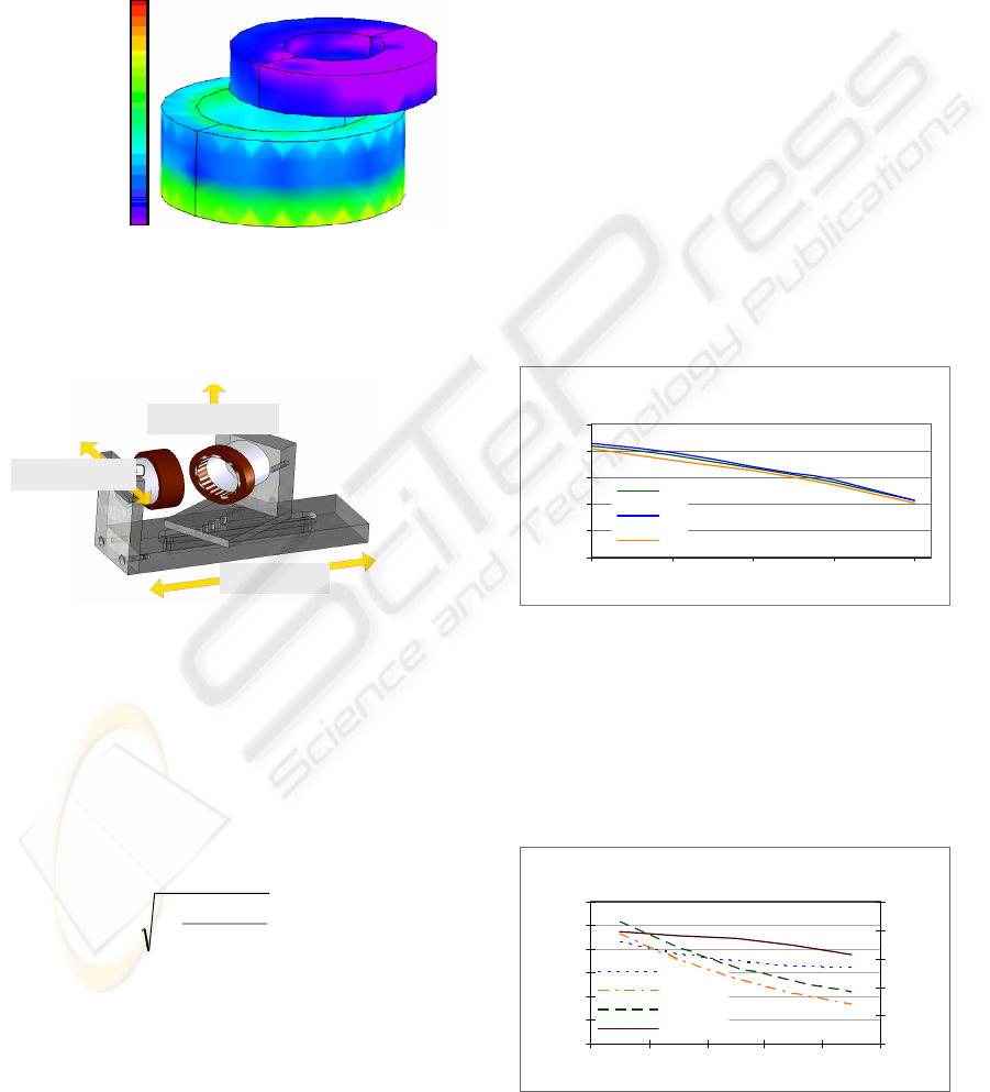
current. Figure 6 shows the magnetic field density
contours for a 20mm laterally displaced secondary
coil with a separation of 10mm. The magnetic field
in the secondary coil is at its highest on the edge
facing the primary and gradually drops off to zero on
the face furthest from the primary.
Figure 6: Magnetic field distribution when the secondary
coil is laterally displaced by 20mm for a separation of
10mm
2.3 Experimental Measurements
Figure 7: CAD model of physical test rig used to hold
primary and secondary coils in known physical
orientation.
A test rig was built (see figure 7) to accurately
locate the primary and secondary coils at known
orientations. The rig allows fixing of the secondary
coil in all three misalignments discussed in the
previous section. Equation 15 was used for
determining the coupling coefficient between the
coils.
openps
shortedps
L
L
k
_
_
1−=
(15)
Where L
ps_shorted
is the primary inductance when
the secondary is shorted, and L
ps_open
is the primary
inductance when the secondary is open, which is
equal to the primary coil inductance L1. At the same
time as acquiring coupling coefficient
measurements, the efficiency of power transfer was
also measured for the whole TET system. The
efficiency was computed as the ratio of the power
delivered to the medical device over the power
drawn from the external battery source supplying the
TET system.
3 COUPLING AND EFFICIENCY
RESULTS
The first evaluation considered a pair of coils with a
very simple geometry which could be accurately
represented using all methods. Both coils used a
single winding and figure 8 illustrates the effect on
the coupling coefficient when the lateral
displacement is increased from 0 to 20 mm at 10mm
separation. The lines ka, ks and kp corresponds to
the coefficient of coupling from the analytical
model, simulated model and experimental
measurements respectively. As expected the
coupling coefficient drops as the lateral
displacement increases, and all three methods
produced consistent results. Similar consistency is
seen for axial alignment and angular rotation cases.
Effect of displacement on coupling at 1cm
seperation
0
0.05
0.1
0.15
0.2
0.25
0 5 10 15 20
Lateral displacement (mm)
Couplin
g
kp
ka
ks
Figure 8: The effect of lateral displacement on coupling at
10mm separation.
However, practical TET coils will not consist of
single turns, and they will have bulk which can be
characterised by internal and external radius and also
a physical height. Physical coils were constructed
with a self inductance of 30.4µH for the primary and
8.75µH for the secondary coil.
Effect of seperation on coupling and
efficiency
0
0.05
0.1
0.15
0.2
0.25
0.3
10 15 20 25 30
Distance (mm)
Couplin
g
40%
50%
60%
70%
80%
90%
Efficiency
ka
ks
kp
Efficiency
Figure 9: Effects of separation between coils on coupling
and efficiency when the coils aligned axially.
2.4e-3
2.0e-3
1.6e-3
1.2e-3
8e-4
4e-4
0e-0
Primar
y
coil
Secondar
y
coil
Uni
t
: Tesla
Rotation Axis
Separation
Displacement
MAGNETIC COUPLING ANALYSIS OF A TET POWER DELIVERY SYSTEM
173
The three methods of evaluating the coupling
coefficient were implemented using genuine
physical parameters, and the results are shown in
figure 9. With the coils aligned axially, the coupling
coefficient decreases as the separation increases. The
simulated coupling coefficients have a mean
deviation of 16% from the experimental results.
However, the analytical results are far away. This is
illustrating the effects of the physical bulk of the
coils. The efficiency of the power transfer is also
shown in figure 9. The coupling coefficient drops at
a greater rate than the efficiency. This is illustrating
that, although the coupling coefficient may be low,
good power efficiency can still be achieved.
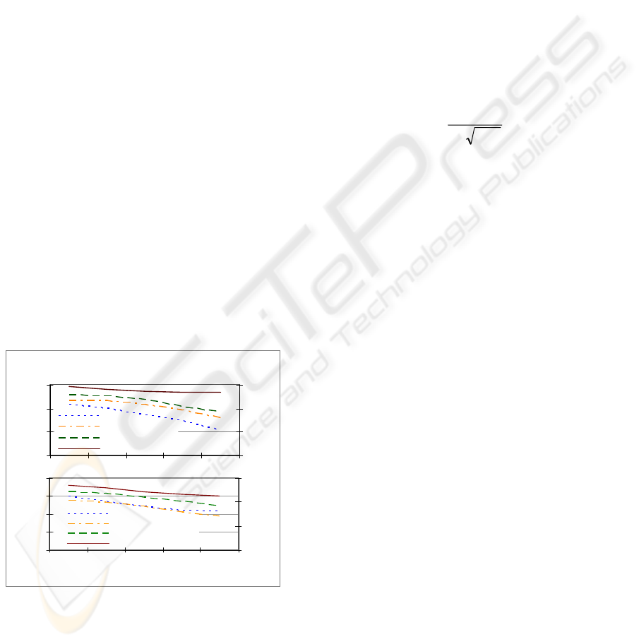
Figure 10 illustrates the effects of displacement
on coupling and efficiency when the coils are
separated by 10mm and 20mm. Again, the simulated
and practical coupling coefficients are fairly similar
(with a mean deviation of 9.5%), while the
analytical model significantly under estimates the
practical result at 10mm separation. However at
20mm separation, the analytical coupling coefficient
is in much better agreement with the simulated
results. This suggests that for lateral displacement at
larger separations, the magnetic coupling for the
physical coils is reasonably well represented by
idealised coils. The effect of lateral displacement on
efficiency was very small (efficiency dropped from
79% to 77% for 20mm lateral displacement) at
10mm separation. Efficiency drops more rapidly
down to 72% at 20mm separation.
Effect of lateral displacement on coupling
and efficiency
0
0.1
0.2
0.3
05101520
Displacement (mm)
Coefficienct of coupling
50%
60%
70%
80%
Efficiency
ka_10 mm
ks _10 mm
kp_10 mm
Efficiency_10 mm
Figure 10: Effects of displacement on coupling and
efficiency for coil separations of 10mm and 20mm.
The impact of rotational misalignment on
coupling was similar to the lateral displacement
case. The simulation result underestimated the
practical coupling for both 10mm and 20mm
separation however it was within a mean deviation
of 14.76% of the experimental measurements.
4 DISCUSSION
The maximum power transfer of a TET system
refers to the maximum power that can be transferred
from primary to secondary coil disregarding the
losses associated with the components in the circuit.
The maximum power that can be transferred by a
current-fed push-pull resonant converter TET system
has been derived by Si et. al. (Ping Si 2007) using
mutual inductance between the primary and
secondary coils. This relationship is shown in
equation 16 as a function of the coupling coefficient.
in
sp
dc
V
LLf
kV
P
8
max
π
=
(16)
Where L
p
and L
s
are the primary and secondary
coil inductances, k is the coupling coefficient, P
max
is
the maximum power transfer, V
in
is the DC input
voltage, V
dc
is the output voltage at the load and f is
the system resonant operating frequency.
Equation 16 is based on the assumption that high
order harmonic components are negligible and the
dc current is continuous at the pickup. These
assumptions are reasonable for practical circuits.
Equation 16 shows that for given primary and
secondary circuits, the maximum power transfer
capacity of a TET system is proportional to the
coupling coefficient. Good coupling can increase the
maximum possible power transfer from primary to
secondary coils. However, in terms of the power
efficiency, from the previous results shown in
section 3, it is clear that coupling does not have a
dramatic effect. This is a very important feature of
the system, meaning it is possible to achieve high
power efficiency for a loosely coupled TET system.
During the power transfer process, there is little
power loss in the air gap between the primary and
the second coils. Therefore the coupling coefficient
is not sensitive to the overall power efficiency of the
system. However with low coupling, high magnetic
strength is required to deliver the same amount of
power, so the required current and/or voltage use to
generate the field needs to be higher, resulting in a
higher loss in the drive circuits. To further
understand the power efficiency issue, the power
losses in each component of the TET system was
identified.
The loss components were measured from the
TET system and are presented in figure 11. The total
power loss between the input and output of the
system was also measured, and the difference
0
0.05
0.1
0.15
0.2
0 5 10 15 20
50%
60%
70%
80%
ka_20 mm
ks_20 mm
kp_20 mm
Efficiency_20 mm
BIODEVICES 2008 - International Conference on Biomedical Electronics and Devices
174

between the sum of the identified primary and
secondary losses, and the actual total losses
measured are presented as “Other” in figure 11. The
experiment was conducted under a constant load of
10W, and the input power to the TET system was
adjusted accordingly for each alignment
configuration to maintain the output power to be
constant.
Power loss contribution
0
1
2
3
4
5
10 15 20 25 30
Distance (mm)
Power loss (W)
Other
Primry loss
Secondary loss
Figure 11: Loss contributions for fully aligned case when
delivering 10W to a load.
Figure 11 shows that the total power loss
increases when the separation between the coils is
larger. However the power loss at the secondary
power circuit is more or less the same due to the
same load and circuit operating condition. This
means no additional losses are occurring at the
secondary even when the coupling is poorer. Thus
there is no complication of temperature rise and risk
of tissue damage.
The increase in total system loss is mainly from
the primary power circuit due to the need for higher
coil currents to compensate when the air gap
separation is larger. A higher strength magnetic field
is needed thus the current in the primary coil and its
tuning capacitor has to be higher, resulting in higher
losses. In this circuit losses in other parts of the
primary converter such as dc conduction losses and
switching losses also increase at the same time due
to the increased dc voltage at the input. However,
they are relatively small because the dc current of
the primary converter is relatively small compared to
the ac resonant current. Therefore (Equivalent Series
Resistance) ESR values for the primary coil and
tuning capacitor are important parameters to
consider in designing an efficient TET system.
5 CONCLUSIONS
Three methods of determining the coupling
coefficient for specific coil orientations covering the
typical range of TET coils suitable for supplying
10W of power are presented in this paper. The
analytical method was shown to be valid for
idealised coil configurations although it could not be
used to model the actual experimental setup
accurately. Numerical simulation gave a superior
match with experimental results, and is appropriate
for assessing different coil designs efficiently.
The coupling coefficient is a major factor
determining the maximum power transfer capacity
of a TET system. However, it does not determine the
system power efficiency. Power losses at the implant
were shown to be largely constant. Therefore there is
no additional heat and temperature rise when the
coupling becomes poorer. A small overall power
efficiency drop was caused mainly by the ESR
losses in the primary circuit. With a maximum coil
separation of 30mm, the variation in coupling
coefficient reduced the overall power efficiency
from approximately 80% to 70%.
REFERENCES
C. M. Zierhofer, E. S. H. (1996). "Geometric approach for
coupling enhancement of magnetically coupled coils."
IEEE transactions on biomedical engineering 43: 708-
714.
F.C Flack, E. D. J., D. M. Schlapp (1971). "Mutual
inductance of air-cored coils: Effects on design of
radio-frequency coupled implants." Medical and
Biological Engineering 9: 79-85.
Hochmair, E. S. (1984). "System optimization for
improved accuracy in transcutaneous signal and power
transmission." IEEE transactions on biomedical
engineering 31: 177-186.
John C. Schuder, J. H. G., Hugh E. Stephenson Jr (1971).
"An inductively coupled RF system for the
transmission of 1kW of power through the skin." IEEE
transactions on biomedical engineering 18: 265-273.
Mani Soma, D. C. G., Robert L. White (1985). "Radio-
frequency coils in implantable devices: Misalignment
analysis and design procedure." IEEE transactions on
biomedical engineering 34: 276-282.
N. de N. Donaldson, T. A. P. (1983). "Analysis of
resonant coupled coils in the design of radio frequency
transcutaneous links." Medical and Biological
Engineering and computing 21: 612-627.
Ping Si, P. A. H., J. W. Hsu, M. Chiang, Y. Wang, Simon
Malpas, David Budgett (2007). "Wireless power
supply for implantable biomedical device based on
primary input voltage reglation." 2nd IEEE conference
on Industrial Electronics and Applications.
MAGNETIC COUPLING ANALYSIS OF A TET POWER DELIVERY SYSTEM
175
