
VISUAL SOFTWARE MODELLING WITH EXTENDED
RULE-BASED MODEL
A Knowledge-based Programming Solution for General Software Design
Grzegorz J. Nalepa and Igor Wojnicki
Institute of Automatics, AGH – University of Science and Technology, Al. Mickiewicza 30, 30-059 Kraków, Poland
Keywords:
Rule-based programming, software modelling, knowledge engineering, automated implementation, XTT.
Abstract:
Rule-based programming paradigm is omnipresent in number of engineering domains. However, there are
some fundamental semantical differences between it, and classic procedural, or object-oriented approaches.
Even though, there has been a lot of effort to use rules to model business logic in classic software no generic
solution has been provided so far. In this paper a new approach for generalized rule-based programming
is given. It is based on a use of advanced rule representation, which includes an extended attribute-based
language, a non-monotonic inference strategy, with explicit inference control on the rule level. The paper
shows how some typical programming constructions, as well as classic programs can be modelled in this
approach. The approach can largely improve both the design and the implementation of complex software.
1 INTRODUCTION
Rule-based programming paradigm is omnipresent in
number of engineering domains such as control and
reactive system, diagnosis and decision support. Re-
cently, there has been a lot of effort to use rules to
model business logic in classic software. However,
there are some fundamental semantical differences
between it, and classic procedural, or object-oriented
approaches. This is why no generic modelling solu-
tion has been provided so far.
The motivation of this paper is to investigate the
possibility of modelling typical programming struc-
tures with an extended forward-chaining rule-based
programming. In this paper a new approach for gen-
eralized rule-based programming is given. It is based
on a use of an advanced rule representation, which in-
cludes an extended attribute-based language (Lig˛eza,
2006), a non-monotonic inference strategy, with ex-
plicit inference control on the rule level. The pa-
per shows, how typical programming constructions
(such as loops), as well as classic mini-programs
(such as factorial) can be modelled in this approach.
It presents possibilities of efficient integration of this
technique with existing software systems.
The paper is composed of several parts. In Sect. 2
basics of the rule-based programming are given, and
in Sect. 3 fundamental differences between software
and knowledge engineering are given. Then, in
Sect. 4 the extended model for rule-based systems
is considered. The application of this model is dis-
cussed in Sect. 5. This model could be integrated in a
classic software system in several ways, considered
in Sect. 6. The research presented in this paper is
a work-in-progress. Some directions for the future
research as well as concluding remarks are given in
Sect. 7.
2 RULE-BASED PROGRAMMING
Rule-Based Systems (RBS) constitute a powerful AI
tool (Negnevitsky, 2002) for specification of knowl-
edge in design and implementation of systems in the
domains such as system monitoring and diagnosis,
intelligent control, and decision support. For the
state-of-the-art in RBS see (Liebowitz, 1998; Jack-
son, 1999; Lig˛eza, 2006). From a point of view of
classical knowledge engineering (KE) a rule-based
expert system consists of a knowledge base and an in-
ference engine. The KE process aims at designing and
evaluating the knowledge base, and implementing the
41
J. Nalepa G. and Wojnicki I. (2007).
VISUAL SOFTWARE MODELLING WITH EXTENDED RULE-BASED MODEL - A Knowledge-based Programming Solution for General Software
Design.
In Proceedings of the Second International Conference on Evaluation of Novel Approaches to Software Engineering , pages 41-47
DOI: 10.5220/0002586600410047
Copyright
c
SciTePress

inference engine. The process of building the knowl-
edge base involves the selection of a knowledge rep-
resentation method, knowledge acquisition, and pos-
sibly low-level knowledge encoding. In order to cre-
ate an inference engine a reasoning technique must be
selected, and the engine has to be programmed.
In the formal analysis of RBS (Lig˛eza, 2006)
some important aspects of the design and implemen-
tation are identified. The first concerns rulebase de-
sign, including: the formal logical language of the
representation, formal syntax of the representation
method, representation expressiveness, which is re-
lated to the expressiveness of the underlying logic,
and particular rule syntax. The second comes down
to the inference engine implementation, including:
inference strategy, interpreter model, including rule
matching method, and conflict resolution algorithm.
In order to design and implement a RBS in an
efficient way, the knowledge representation method
should support the designer, introducing a scalable vi-
sual representation. As the number of rules exceeds
even relatively very low quantities, it is hard to keep
the rule-base consistent, complete, and correct. These
problems are related to knowledge-base verification,
validation, and testing. To meet security requirements
a formal analysis and verification of RBS should be
carried out (Vermesan and Coenen, 1999). This anal-
ysis usually takes place after the design stage. How-
ever, there are design and implementation methods,
such as the XTT, that allow for on-line verification
during the design and gradual refinement of the sys-
tem.
Supporting rulebase modelling remains an essen-
tial aspect of the design process. In this area number
of approaches are present. The simplest one consists
in writing rules in the low-level RBS language, such
as one of Jess (www.jessrules.com). A more so-
phisticated approaches are based on the use of some
classic visual rule representations. This is a case of
LPA VisiRule, (www.lpa.co.uk) which uses decision
trees. Approaches such as XTT (Nalepa, 2004) aim at
developing a new language for visual rule modelling.
While RBS found wide range of industrial appli-
cations in „classic AI domains” e.g. decision support,
system diagnosis, or intelligent control, the technol-
ogy did not find applications in the mainstream soft-
ware engineering – due to some fundamental differ-
ences between knowledge and software engineering.
3 SOFTWARE AND
KNOWLEDGE ENGINEERING
Rule-based systems (RBS) constitute today one of
the most important classes of the so-called Knowl-
edge Based Systems (KBS). Building real-life KBS
is a complex task. Since their architecture is fun-
damentally different from classic software, typical
Software Engineering approaches cannot be applied
efficiently. Some specific development methodolo-
gies, commonly referred to as Knowledge Engineer-
ing (KE), are required.
What makes KBS distinctive is the separation of
knowledge storage (the knowledge base) from the
knowledge processing facilities. In order to store
knowledge, KBS use various knowledge representa-
tion methods, which are declarative in nature. In case
of RBS these are production rules. Specific knowl-
edge processing facilities, suitable for particular rep-
resentation method being used, are selected then. In
case of RBS these are logic-based inference engines.
The knowledge engineering process, involves two
main tasks: knowledge base design, and inference en-
gine implementation. Furthermore, other tasks are
also required, such as: knowledge base analysis and
verification, and inference engine optimization. The
performance of a complete RBS should be evaluated
and validated. While this process is specific to expert
systems, it is usually similar in case of other KBS.
What is important about the process, is the fact
that it should capture the expert knowledge and rep-
resent it in a way that is suitable for processing (this is
the task for a knowledge engineer). The actual struc-
ture of a KBS does not need to be system specific – it
should not „mimic” or model the structure of the real-
world problem. However, the KBS should capture
and contain knowledge regarding the real-world sys-
tem. The task of programmers is to develop process-
ing facilities for the knowledge representation. The
level at which KE should operate is often referred
to as the knowledge level (Newell, 1982). It should
be pointed out, that in case of KBS there is no sin-
gle universal engineering approach, or universal mod-
elling method (such as UML in software engineer-
ing). Different classes of KBS may require specific
approaches, see (Lig˛eza, 2006; Torsun, 1995).
Software engineering (SE) is a domain where a
number of mature and well-proved design methods
exist; furthermore, the software development process
and its life cycle is represented by several models.
One of the most common models is called the water-
fall model (Sommerville, 2004). In the software engi-
neering process a number of development roles can be
identified: users and/or domain experts, system ana-
ENASE 2007 - International Conference on Evaluation on Novel Approaches to Software Engineering
42

lysts, programmers, testers, integrators, and end users
(customers). What makes this process different from
knowledge engineering is the fact that systems ana-
lysts try to model the structure of the real-world infor-
mation system in the structure of computer software
system. So the structure of the software corresponds,
to some extent, to the structure of the real-world sys-
tem. Then programmers encode and implement the
model (which is the result of the system analysis) in
some lower-level programming language.
The important difference between SE and KE, is
that the former tries to model how the system works,
while the latter tries to capture and represent what is
known about the system. The knowledge engineering
approach assumes that information about how the sys-
tem works can be inferred automatically from what is
known about the system (Nalepa, 2005).
The fundamental differences between the KE and
SE approaches include:
• declarative vs. procedural point-of-views,
• clear semantic gaps in the SE process, between
the requirements, design, and implementation,
• the application of gradual abstraction as the main
approach to the design of KBS.
The solution introduced in this paper aims at integrat-
ing a classic KE methodology of RBS with SE. The
model considered here, based on the XTT method
could serve as an effective bridge between SE and KE.
4 EXTENDED RULE-BASED
MODEL
The approach considered in this paper is based on
an extended rule-based model. The model uses the
XTT knowledge method with certain modifications.
The XTT method was aimed at forward chaining rule-
based systems. In order to be applied to general
programming it is modified in several aspects. Fur-
thermore, it proved to be robust and highly effective
combining features of decision tables and decision
trees (Nalepa, 2004).
4.1 XTT – Extended Tabular Trees
The XTT (EXtended Tabular Trees) knowledge repre-
sentation (Nalepa, 2004; Nalepa and Lig˛eza, 2005a),
has been proposed in order to solve common design,
analysis and implementation problems with RBS. In
this method three representation levels are addressed:
• visual – the model is represented by a hierarchical
structure of linked extended decision tables,
A1 An −X +Y H
a11 a1n x1 y1 h1
am1 amn xm ym hm
Figure 1: A single XTT table.
• logical – tables correspond to sequences of ex-
tended decision rules,
• implementation – rules are processed using a Pro-
log representation.
On the visual level the model is composed of ex-
tended decision tables. A single table is presented in
Fig. 1. The table represents a set of rules, having the
same attributes.
A rule can be read as follows:
IF (A11 ∈ a11) ∧ .. .(A1n ∈ a1n) T HEN
retract(X = x1), assert(Y = y1),do(H = h1).
It includes two extensions compared to classic RBS:
• non-atomic attribute values, used both in condi-
tions and decisions,
• non-monotonic reasoning support, with dynamic
assert, retract operations in decision part.
Every table row corresponds to a decision rule. Rows
are interpreted from the top row to the bottom one.
Tables can be linked in a graph-like structure. A link
is followed when rule (row) is fired.
There are tools (see (Nalepa, 2004; Nalepa and
Lig˛eza, 2005b))which support the design process us-
ing the above visual model. They are capable of defin-
ing attributes, creating linked XTT tables, and last but
not least running the inference process. There is also
an ongoing research to make these tools cover func-
tionality presented in Sect. 4.2.
On the logical level a table corresponds to a num-
ber of rules, processed in a sequence. If a rule is fired
and it has a link, the inference engine processes the
rule in another table. The rule is based on a attribu-
tive language (Lig˛eza, 2006).
It corresponds to a Horn clause:
¬p
1
∨ ¬p
2
∨ ... ∨ ¬p
k
∨ h
where p is a literal in SAL (set attributive logic)
(see (Lig˛eza, 2006)) in a form:
A
i
(o) ∈ t
where o ∈ O is a object referenced in the system, and
A
i
∈ A is a selected attribute of this object (property),
VISUAL SOFTWARE MODELLING WITH EXTENDED RULE-BASED MODEL - A Knowledge-based Programming
Solution for General Software Design
43

t ⊆ D
i
is a subset of attribute domain A
i
. Rules are
interpreted using a unified knowledge and fact base,
that can be dynamically modified during the infer-
ence process using Prolog-like assert/retract operators
in rule decision.
Rules are implemented using Prolog-based repre-
sentation (see (Nalepa and Lig˛eza, 2006)). Rule rep-
resentation uses Prolog terms, which is a very flexi-
ble solution. However, it requires a dedicated meta-
interpreter (Covington et al., 1996; Bratko, 2000).
This model has been successfully used to model
classic rule-based expert systems. For the needs of
general programming described in this paper, some
important modifications are proposed.
4.2 XTT Enhancements
Considering the use of XTT for general appli-
cations, there have been several extensions pro-
posed regarding the base XTT model. These are:
Grouped Attributes, Attribute-Attribute Comparison,
Not-Defined Operator, Link Labeling, Scope Opera-
tor, Multiple Rule Firing. Applying these extensions
constitute the XTT Plus (or XTT+ for short).
Grouped Attributes provide means for putting to-
gether some number of attributes to express relation-
ships among them and their values. As a result a com-
plex data structure, called a group, is created which
is similar to constructs present in programming lan-
guages (i.e. C language structures).
A group is expressed as:
Group(Attrinbute1, Attribute2,... ,AttributeN)
Attributes within a group can be referenced by
their name: Group.Attribute1 or position within the
group: Group/1. An application of such Grouped
Attributes could be expressing spatial coordinates:
Position(X,Y ) where Position is the group name, X
and Y are attribute names.
The Attribute-Attribute Comparison concept in-
troduces powerful mechanism to the existing XTT
comparison model. In addition to comparing an at-
tribute value against a constant (Attribute-Value Com-
parison) it allows for comparing an attribute value
against another attribute value.
The Attribute-Value Comparison can be expressed
as a condition:
if (Attribute OPERATOR Value) then ...
where OPERATOR is a comparison operator i.e. equal,
greater then, less than etc., while Attribute-Attribute
Comparison is expressed as a condition:
if (Attribute1 OPERATOR Attribute2) then ...
where OPERATOR is a comparison operator or a func-
tion in a general case:
if (OPERATOR(Att1,...,AttN)) then ...
The proposed Not-Defined (N/D) operator checks
if a value for a given attribute has been defined. It has
a broad application regarding modelling basic pro-
gramming structures, i.e. to make a certain rule fired
if the XTT table can be executed for the first time.
The Link Labeling concept allows to reuse certain
XTTs, which is similar to subroutines in procedural
programming languages. Such a reused XTT is ex-
ecuted in several contexts. There are incoming and
outgoing links. Links are labeled, if control comes
from a labeled link it has to be directed through an
outgoing link with the same label. There can be mul-
tiple labeled links for a single rule then. If an outgo-
ing link is not labeled it means that if a corresponding
rule is fired the link will be followed regardless of the
incoming link label. Such a link (or links) might be
used to provide control for exception-like situations
or making a set of XTTs reusable.
The graphical Scope Operator provides a basis for
modularized knowledge base design. It allows for
treating a set of XTT as a certain Black Box with well-
defined input/output. Outside the given scope only
conditional attributes for the incoming links and con-
clusion attributes for the outgoing links are visible.
Scope Operators make the knowledge base more
scalable and it provides modularity. Furthermore it al-
lows rule management at the scope level, managing a
given scope, or set of scopes. This includes checking
rule consistency within a given scope.
Since multiple values for a single attribute are al-
ready allowed, it is worth pointing out the the new in-
ference engine being developed treats them in a more
uniform and comprehensive way. If a rule is fired and
the conclusion or assert/retract use a multivalue at-
tribute such a conclusion is executed as many times
as there are values of the attribute. It is called Mul-
tiple Rule Firing. This behavior allows to perform
aggregation or set based operations easily.
5 MODELLING SOFTWARE
WITH RULES
The XTT+ can be applied in other domains than RBS.
The section presents typical programming constructs
developed using the XTT+ model.
5.1 Basic Programming Structures
Two main constructs considered here are: a condi-
tional statement, and a loop. Programming a condi-
tional with rules is both simple and straightforward,
ENASE 2007 - International Conference on Evaluation on Novel Approaches to Software Engineering
44
F G
ANY
+F FC
=V
ANY
ANY
else then
ANY
G
ANY
f2
g1
g2
f1
h2
h1 f4
f3
g4
g3
h4
h3
+F
Figure 2: A conditional statement.
X
while
I
ANY
I
N/D
ANY ANY
ANY ANY
=I+1
=0
>Z
ANY
ANY
ANY
+Y
ANYANYc h
Figure 3: A loop statement.
since a rule is by definition a conditional statement. In
Fig. 2 two table system is presented. The first row of
the else table represents the main conditional state-
ment using attribute C, while the remaining rows im-
plement the statements executed on attributes G and F
when the condition is not met. If the condition is met,
then the other table, simply called then is executed.
A loop can be easily programmed, using the dy-
namic fact base modification feature. In Fig. 3 a
simple system implementing the for-like loop is pre-
sented. In the XTT table the initial execution, as well
as the subsequent ones are programmed. The I at-
tribute serves as the index. In the body of the loop the
value of the decision attribute Y is modified depend-
ing on the value of the conditional attribute X. The
loop ends when the index value is greater then Z. This
could be easily generalized into the while loop.
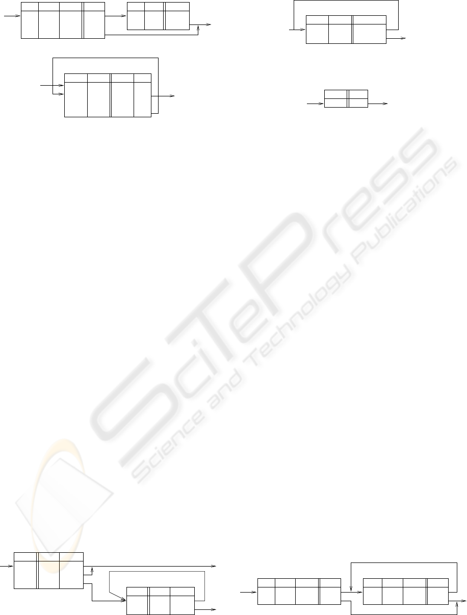
5.2 Simple Programming Cases
A set of rules to calculate a factorial is given in Fig. 4.
An argument is given as attribute X. The calculated
result is given as Y . The iterative algorithm is imple-
mented which uses S attribute as a counter.
Since an attribute can be assigned more than a sin-
gle value (i.e. using the assert feature), certain op-
erations can be performed on such a set (It is sim-
ilar to aggregation operations regarding Relational
Databases). An example of sum function is given in
Fig. 5. It adds up all values assigned to X and stores
the result as the value of Sum attribute. The logic be-
S
N/D
Y
=1
X
=1
=0
>1
factorial0
N/D
=X
=1
=1
S
factorial1
>1
=1
Y S
=Y*S =S−1
ANY N/D
Figure 4: Factorial implementation.
X
sum
Sum
ANY
Sum
N/D =0
ANY ANY =Sum+X
Figure 5: Sum implementation.
X
ANY
+Y
=X
copy
Figure 6: Copying elements of a set.
hind is as follows. If Sum is not defined then make it
0 and loop back. Than, the second rule is fired, since
Sum is already set to 0. The conclusion is executed as
many times as values are assigned to X . If Sum has a
value set by other XTTs prior to the one which calcu-
lates the sum, the result is increased by this value.
Assigning a set of values to an attribute based on
values of another attribute is given in Fig. 6. The
given XTT populates Y with all values assigned to X .
It uses the XTT assert feature.
Using XTT even complex task such as browsing a
tree can be implemented easily. A set of XTTs finding
successors of a certain node in a tree is given in Fig.7.
It is assumed that the tree is expressed as group of
attributes t(P,N), where N is a node name, and P is
a parent node name. The XTTs find all successors of
a node which name is given as a value of attribute P
(it is allowed to specify multiple values here). A set
of successors is calculated as values of F. The first
XTT (labeled tree1) computes immediate child nodes
of the given one. If there are any child nodes control is
passed to the XTT labeled tree2. It finds child nodes
of the children computed by tree1 and loops over to
find children’s children until no more child nodes can
be found. The result is stored as values of F.
6 MODEL INTEGRATION
The XTT+ has been discussed on the conceptual level
of the visual representation. Two approaches to pro-
vide a runtime environment are considered.
The first one consists in generating native code in
t.P t.N
ANY
N/D
+F
=t.N
t.N +F
=t.N
t.PF
=F ANY
=F N/D ANYANY
P
ANY
ANY
=P
=P
tree1 tree2
ANY
ANY
Figure 7: Finding successors in a tree.
VISUAL SOFTWARE MODELLING WITH EXTENDED RULE-BASED MODEL - A Knowledge-based Programming
Solution for General Software Design
45

an object-oriented language such as Java. This solves
both the practical implementation as well as runtime
problem. This solution is used in products such as
JBoss Rules (formerly Drools). However, it does has
a major drawback: the object-oriented semantics is
very distant from the declarative rule semantics of
XTT+. This instantly unveils a semantic gap which
turns out to be a major limitation during the imple-
mentation and testing of the system. Furthermore,
while a translation from XTT+ to object-oriented if
fairly simple, a reversed one is complicated.
The second approach is based on using a high
level Prolog representation of XTT. Prolog seman-
tics includes all of the concepts present in the XTT+.
It has the advantages of flexible symbolic repre-
sentation, as well as advanced meta-programming
facilities (Covington et al., 1996; Bratko, 2000).
The XTT+-in-Prolog solution is based on the Pro-
log implementation, presented in (Nalepa and Lig˛eza,
2006). In this case a term-based representation is
used, with an advanced meta interpreter engine pro-
vided. There are two ways of the integration of
the Prolog-based XTT+ model with a Java applica-
tion. The first one consists in linking the Prolog-
based XTT+ interpreter with a Java application us-
ing Prolog-to-Java interface provided for some ad-
vanced Prolog implementations, such as SWI (www.
swi-prolog.org). In this approach the SWI Prolog
JPL interface is being used to communicate from the
Prolog programs with Java objects. Another one re-
lies on the idea of embedding the whole interpreter in
a Java application, with use of Java-based Prolog in-
terpreters. So far the JIProlog (www.ugosweb.com/
jiprolog) has been considered.
Furthermore, the integration could be considered
on an architectural level. The idea is to use the Mode-
View-Controller (MVC) pattern (Burbeck, 1992). In
this case the XTT+ would be used to build the ap-
plication logic model, where-as other parts of the ap-
plication, mainly the interface could be built with
object-oriented languages such as Java. The appli-
cation logic interfaces with object-oriented compo-
nents. These components provide means for inter-
action with environment which is user interface and
general input-output operations. It is also possible to
extend the model with arbitrary code. There are sev-
eral scenarios possible regarding interactions between
the model and the environment. In general, they can
be subdivided into output and input schemas. These
schemas provide view and controller functionalities.
The input schema takes place upon checking con-
ditions required to fire a rule. A condition may re-
quire input operations. A state of such a condition is
determined by the data from the environment. Such
a data could be user input, file contents, a state of an
object, a result from a function. The input operation
could be blocking or non-blocking providing basis for
synchronization with environment. The input schema
acts as the controller regarding the MVC approach.
The output schema takes place if a conclusion re-
gards an output operation. In such a case the opera-
tion regard general output (i.e. through user interface),
spawning a method or function, setting a variable etc.
A conclusion also carries its state which is true or
false depending on whether the output operation suc-
ceeded or failed respectively. If the conclusion fails,
the rule fails as well. The output schema acts as the
view regarding the MVC approach.
7 CONCLUDING REMARKS
Rule-based programming paradigm plays an impor-
tant role in number of engineering domains. The fun-
damental semantical differences between it, and clas-
sic programming approaches do not allow for using it
to model business logic in classic software.
In the paper the research in the field of knowl-
edge and software engineering is presented. The re-
search aims at the unification of knowledge engineer-
ing methods with software engineering. The paper
presents a new approach for generalized rule-based
programming called XTT+. It is based on the use of
advanced rule representation, which includes an ex-
tended attribute-based language, a non-monotonic in-
ference strategy, with explicit inference control.
The original contribution of the paper consists in
the extension of the XTT rule-based systems knowl-
edge representation method, into XTT+, a more gen-
eral programming solution; as well as the demon-
stration how some typical programming constructions
and classic programs can be modelled in this ap-
proach. Furthermore XTT+ is fully integrable with
existing object-oriented programming languages such
as Java. The integration is provided based on the
Model-View-Controller concept. Future work will be
focused on representation extensions and use cases.
The original XTT has been applied to control sys-
tems, and selected security systems. The application
of XTT+ will be also extended towards business rules
systems, with richer semantics.
In its current stage, XTT+ can successfully model
number of programming constructs and approaches.
This proves XTT+ can be applied as a general pur-
pose programming environment. However, the re-
search should be considered an experimental one, and
definitely a work in progress.
ENASE 2007 - International Conference on Evaluation on Novel Approaches to Software Engineering
46

ACKNOWLEDGEMENTS
The paper is supported by the HEKATE Project
funded from 2007–2008 resources for science as a re-
search project.
Research supported from AGH University Grant
No.: 11.11.120.44
REFERENCES
Bratko, I. (2000). Prolog Programming for Artificial Intel-
ligence. Addison Wesley, 3rd edition.
Burbeck, S. (1992). Applications programming in
smalltalk-80(tm): How to use model-view-controller
(mvc). Technical report, Department of Computer
Science, University of Illinois, Urbana-Champaign.
Covington, M. A., Nute, D., and Vellino, A. (1996). Prolog
programming in depth. Prentice-Hall.
Jackson, P. (1999). Introduction to Expert Systems.
Addison–Wesley, 3rd edition. ISBN 0-201-87686-8.
Liebowitz, J., editor (1998). The Handbook of Applied Ex-
pert Systems. CRC Press, Boca Raton.
Lig˛eza, A. (2006). Logical Foundations for Rule-Based Sys-
tems. Springer-Verlag, Berlin, Heidelberg.
Nalepa, G. J. (2004). Meta-Level Approach to Integrated
Process of Design and Implementation of Rule-Based
Systems. PhD thesis, AGH University of Science and
Technology, AGH Institute of Automatics, Cracow,
Poland.
Nalepa, G. J. (2005). Rule-based systems design and im-
plementation : methodologies and technologies. In
Ryszard Tadeusiewicz, Antoni Lig˛eza, M. S., editor,
CMS’05. Plenary lectures and special session papers
: Computer Methods and Systems, volume 1, pages
329–340, Kraków, Poland. AGH University of Sci-
ence and Technology Cracow, Jagiellonian University,
Cracow University of Technology, Oprogramowanie
Naukowo-Techniczne.
Nalepa, G. J. and Lig˛eza, A. (2005a). A graphical tabular
model for rule-based logic programming and verifica-
tion. Systems Science, 31(2):89–95.
Nalepa, G. J. and Lig˛eza, A. (2005b). A visual edition tool
for design and verification of knowledge in rule-based
systems. Systems Science, 31(3):103–109.
Nalepa, G. J. and Lig˛eza, A. (2006). Prolog-based anal-
ysis of tabular rule-based systems with the xtt ap-
proach. In Sutcliffe, G. C. J. and Goebel, R. G., ed-
itors, FLAIRS 2006: proceedings of the 19th interna-
tional Florida Artificial Intelligence Research Society
conference, pages 426–431. AAAI Press.
Negnevitsky, M. (2002). Artificial Intelligence. A Guide to
Intelligent Systems. Addison-Wesley, Harlow, Eng-
land; London; New York. ISBN 0-201-71159-1.
Newell, A. (1982). The knowledge level. Artificial Intelli-
gence, 18(1):87–127.
Sommerville, I. (2004). Software Engineering. Interna-
tional Computer Science. Pearson Education Limited,
7th edition.
Torsun, I. S. (1995). Foundations of Intelligent Knowledge-
Based Systems. Academic Press, London, San Diego,
New York, Boston, Sydney, Tokyo, Toronto.
Vermesan, A. and Coenen, F., editors (1999). Validation
and Verification of Knowledge Based Systems. The-
ory, Tools and Practice. Kluwer Academic Publisher,
Boston.
VISUAL SOFTWARE MODELLING WITH EXTENDED RULE-BASED MODEL - A Knowledge-based Programming
Solution for General Software Design
47
