
GENERATING OPTIMIZED MARKER-BASED RIGID BODIES
FOR OPTICAL TRACKING SYSTEMS
Frank Steinicke, Christian Jansen and Klaus Hinrichs
Institut f
¨
ur Informatik, WWU M
¨
unster, Einsteinstr. 62, 48149 M
¨
unster, Germany
Jan Vahrenhold
Informatik XI, Universit
¨
at Dortmund, 44221 Dortmund, Germany
Bernd Schwald
TWT GmbH, Information & Engineering Technologies, 73765 Neuhausen, Germany
Keywords:
Optical tracking, model-based object tracking, rigid bodies.
Abstract:
Marker-based optical tracking systems are often used to track objects that are equipped with a certain number
of passive or active point markers. Fixed configurations of these markers, so-called rigid bodies, can be
detected by, for example, infrared stereo-based camera systems, and their position and orientation can be
reconstructed by corresponding tracking algorithms. The main issue in designing the geometrical constellation
of these markers and their 3D positions is to allow robust identification and tracking of multiple objects, and
this design process is considered to be an essential and challenging task. At present, the design process is based
on trial-and-error: the designer constructs a marker configuration, evaluates it in a given setup, and rearranges
the marker positions within the configuration if necessary. Even though single ready-made rigid bodies permit
sufficiently good tracking, it is not ensured that the corresponding arrangements of markers meet any quality
criteria in terms of reliability and robustness. Furthermore, it is unclear whether it is possible to add further
rigid bodies to the setup which are sufficiently distinguishable from the given ones.
In this paper, we present an approach to semi-automatically generate marker-based rigid bodies which are op-
timal with respect to the properties of the tracking system for which they are used, e.g., granularity, accuracy,
or jitter. Our procedure which is aimed at supporting the design process as well as improving tracking gen-
erates configurations for several devices associated with an arbitrary set of point-based markers. We discuss
both the technical background of our approach and the results of an evaluation comparing the tracking quality
of commercially available devices to the rigid bodies generated by our approach.
1 INTRODUCTION
The usage of optical tracking systems based on in-
frared (IR) light is becoming more and more com-
mon for virtual, augmented or so-called mixed re-
ality (MR) systems used in several application do-
mains. This is due to the fact that these systems
provide a large interaction space and quite high ac-
curacy, and in contrast to mechanical approaches no
wires disturb the interaction. Furthermore no interfer-
ences may occur as when using magnetic or ultrasonic
technology. Nowadays IR-based optical tracking sys-
tems exist as prototypes in research institutes (Kato
and Billinghurst, 1999; Dorfm
¨
uller-Ulhaas, 2002;
Schwald, 2005; Ribo et al., 2001) and are also com-
mercially available (A.R.T., 2006; Fakespace Sys-
tems, 2006). The main issue in designing tracking
system is to advance both hardware as well as algo-
rithms in order to increase the accuracy and robust-
ness. These factors are the most important properties
to make such a system usable for applications, e.g., in
medicine or MR environments in general.
When using such systems objects or devices to
be tracked are associated with so-called rigid bodies,
sometimes denoted as targets (Schwald, 2005; Kato
and Billinghurst, 1999; Dorfm
¨
uller-Ulhaas, 2002). A
rigid body is a fixed geometrical arrangement of at
least three passive or active IR markers. A calibrated
camera system allows to reconstruct the 3D coordi-
nates of IR point-based markers in the tracking coor-
387
Steinicke F., Jansen C., Hinrichs K., Vahrenhold J. and Schwald B. (2007).
GENERATING OPTIMIZED MARKER-BASED RIGID BODIES FOR OPTICAL TRACKING SYSTEMS.
In Proceedings of the Second International Conference on Computer Vision Theory and Applications - IU/MTSV, pages 387-395
Copyright
c
SciTePress

dinate system if at least two cameras can detect the
same marker (Zhang, 2000). A rigid body registered
by the tracking system, can be tracked by means of
the fixed known distances between its markers.
In many MR applications, devices like head
mounted displays, stereo glasses or interaction de-
vices, e.g., gloves or wands, have to be tracked (Bow-
man et al., 2004). Often these devices do not require
more than three, four or five markers, arranged in a
target attached to such a device. For instance, a typi-
cal setup in a co-located MR environment consists of
two users, each equipped with an interaction device
and stereo glasses each including approximately three
to five markers. However, some applications need
to track more complicated objects requiring a much
larger number of markers. This occurs, for example,
when tracking real objects having several markers at-
tached on different sides in order to avoid occlusions.
Usually, rigid bodies are defined by the developer
or an interaction device designer by arranging mark-
ers around the object respectively device to be tracked
(Davis et al., 2004). When arranging markers on such
an object it is essential to arrange them in such a way
that the distances between all markers are pairwise
different if possible. Otherwise the tracking system
may mistake distances and the corresponding device
will not be recognized. For each new marker to be
integrated into a configuration consisting of n mark-
ers n new distances have to be considered. For ex-
ample, when building a simple target including three
markers, adding a fourth marker requires the designer
to consider three new distances. Moving one marker
in a configuration of four markers may change three
distances that have to be pairwise different and differ-
ent from each of the distances of the remaining three
markers. Thus, although finding a well-defined con-
figuration seems to be simple it involves a non-trivial
task of arranging the markers especially if several de-
vices with numerous markers are included.
However, when constructing a target usually the
markers are arranged by trial-and-error. After a pro-
totype rigid body has been built, the application de-
veloper or user has to test the corresponding device in
a laboratory setup. If the test shows bad rigid body
performance, the designer has to rebuild the device.
A bad rigid body performance means that the device
is often not tracked or it is tracked with position or
orientation errors which do not result from accuracy
errors of the used tracking system; these mistakes re-
sult from confusing distances within the same config-
uration or between different configurations.
After several iterations of building, testing and re-
defining, the designer may have constructed a con-
figuration that provides sufficient tracking properties.
However, even when ready-made targets are tracked
well, it is not ensured that the corresponding arrange-
ments of markers are optimal in terms of reliability
and robustness and if it is possible to add further tar-
gets to the setup that are distinguishable from the al-
ready designed ones. Typically, targets built via such
a procedure consist of distances which have the po-
tential to disturb the tracking process. For instance,
distances within the same target or distances of dif-
ferent targets used for the interaction may be equal.
In order to support the arrangement of markers in
a target we present a procedure to semi-automatically
generate marker-based rigid bodies in an iterative
way. When using our approach the proposed con-
figurations are adapted to the properties of the corre-
sponding tracking system, e.g., granularity, accuracy,
jitter etc., and thus the described concepts enhance the
tracking process. Our procedure allows to generate
rigid bodies for several devices associated with an ar-
bitrary set of markers. This paper describes the tech-
nical background of our approach and the results of an
evaluation comparing commercially available devices
with their associated targets to rigid bodies proposed
by our approach.
The remainder of this paper is structured as fol-
lows. Section 2 outlines the concepts of optical track-
ing and explains how 3D points are generated from
2D images of point-based markers grabbed with at
least two cameras. In Section 3 we describe how rigid
bodies are defined and how the detection of a config-
uration is performed by the tracking system. Section
4 explains our algorithm to generate configurations
semi-automatically in an iterative way. In Section 5
we present an evaluation of our concept and show how
we could increase the performance of the devices by
redefining two example targets. Section 6 concludes
the paper and gives an overview about future research
directions.
2 INFRARED-BASED OPTICAL
TRACKING
Since the brightness of most MR systems, e.g.,
CAVEs, PowerWalls, etc., is relatively limited, many
projection-based environments require a significant
reduction of the ambient light. To overcome the re-
sulting lighting problem for the cameras, an infrared
(IR) optical tracking systems illuminates the scene us-
ing infrared light, and IR pass filters are attached to
the lenses of the tracking system’s cameras. Infrared
optical tracking systems aim at measuring the (real-
world) positions of numerous markers in the envi-
ronment. Since active markers such as light-emitting
VISAPP 2007 - International Conference on Computer Vision Theory and Applications
388

During the tracking process, the relation between
the current position and orientation of a given target
and the position of its reference position/orientation
specifies the rigid body transformation of the target.
This rigid body transformation is applied to a virtual
object which is associated with a corresponding tar-
get, i.e., the transformation matrix describing the rigid
body transformation is applied to the associated scene
object visualized in the virtual environment.
To further increase the effectiveness of the track-
ing algorithm, learning algorithms may be used that
aim at enhancing the tracking process, e.g., by tuning
the distances predefined manually in the reference tar-
get with respect to measured distances (Figueriredo,
2002; Kanbara et al., 2001).
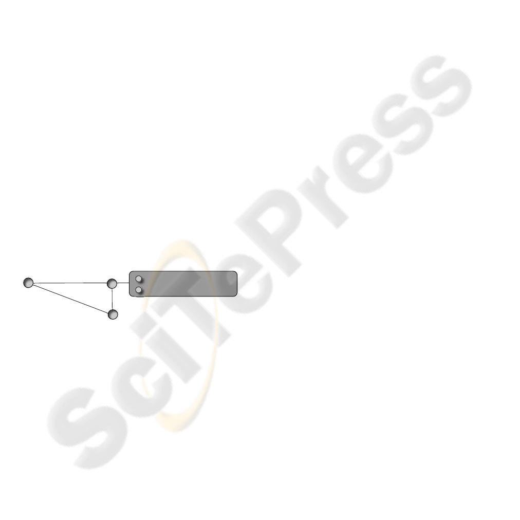
3.1 Description
A target used to track an input device is a configu-
ration of a set of markers where one of the markers
serves as a local reference point. As an example, con-
sider the six-degrees-of-freedom interaction device
depicted in Figure 3. The target attached to this de-
vice consists of three markers where the point m
1
:=
(0, 0, 0) is associated with the marker at the top of
the input device, point m
2
:= (−73.0, 0.0, −188.72)
is associated with the marker in front of the handle,
and m
3
:= (0.0, 0.0, −181.25) is associated with the
marker at the top of the stick branched to the left. The
positions of the markers are given as relative coordi-
nates (in millimeters) in the Cartesian coordinate sys-
tem with the origin at m
1
.
m
1
m
2
m
3
d
12
d
23
d
13
Figure 3: Example device with an associated with a rigid
body consisting of three markers.
In general, such targets can be defined by two dif-
ferent procedures: (1) storing the (absolute) positions
of the markers or (2) storing the relative distances
between the markers as well as its reference posi-
tion/orientation. We use the second alternative and
apply a matrix representation for the distances
D
M
= {d(m
i
, m
j
) | m
i
, m
j
∈ M ; i, j = 1, ..., n} (1)
where M is the set of all markers in a configuration
consisting of n markers, and d(m
i
, m
j
) denotes the
Euclidean distance between two markers m
i
and m
j
in 3D-space.
The quadratic n × n-dimensional matrix D =
(d
i j
:= d(m
i
, m
j
))
i, j=1,...,n
stores the distances induced
by the configuration and has the following form:
D
M
=
0 d
12
d
13
. . . d
1n
d
21
0 d
23
. . . d
2n
d
31
d
32
0 . . . d
3n
.
.
.
.
.
.
.
.
.
.
.
.
.
.
.
d
n1
d
n2
d
n3
. . . 0
(2)
From (1) and (2), it follows:
1. d(m
i
, m
i
) = 0, and
2. d is symmetric, i.e., d(m
i
, m
j
) = d(m
j
, m
i
).
To ensure that no errors occur in determining the cor-
rect rigid body transformation, we also desire that
d(m
i
, m
j
) are pairwise different for all 1 ≤ i < j ≤ n.
3.2 Detection
The above matrix-based description of rigid bodies
can be used to identify the rigid body by means of
distance detection. When tracking a target taken from
a set of several predefined rigid bodies, the tracking
algorithm scans the 3D point cloud P resulting from
the reconstruction of the detected markers. While do-
ing so, the algorithm tries to match point-to-point dis-
tances in P to distances d
i j
= d(m
i
, m
j
) stored in the
i-th row and j-th column of each matrix D that de-
scribes one of the predefined rigid bodies (see (2)).
If any d
i j
varies by at most a distance threshold of
ε from some d ∈ D
M
, i.e., if
|d − d
i j
| < ε, (3)
it is assumed that d = d
i j
, and — assuming that
all distances are unique — the first two markers of
a target T , m
i
and m
j
, are detected within the point
cloud P . Otherwise the algorithm scans P for the next
distance stored in D
M
.
The algorithm continues searching until a third
marker m
k
has been found or the search space is ex-
hausted. If a third marker m
k
is identified by detect-
ing the distances d
ik
or d
jk
in the point cloud, the
rigid body transformation of this target with respect to
its reference position can be determined (Dorfm
¨
uller-
Ulhaas, 2002). From Equation (3), we see that if
we choose ε to small, distances may not be found
due to accuracy errors. If the threshold is chosen too
high, there may be ambiguities with other distances.
This may result in tracking of targets with wrong po-
sition/orientation or to confusions between targets.
Hence, the threshold must be carefully adapted in or-
der to increase the reliability of the tracked data.
VISAPP 2007 - International Conference on Computer Vision Theory and Applications
390
4 GENERATION OF TARGETS
Assuming that the shape and size of the markers are
identical for each rigid body we focus on improv-
ing the tracking performance by means of redefining
positions of markers within a target in order to be
able to support the largest possible distance thresh-
old. Hence, the main idea is to arrange the markers in
such a way that the resulting distances between each
pair of markers are as diverse as possible with respect
to the granularity of the tracking system and already
existing configurations.
4.1 Iterative Approach
Let D
M
r
denote the set of all distances of the r-th
rigid body, which consists of the marker set M
r
. Fur-
thermore, let D denote the union of all D
M
r
for all
rigid bodies registered at the tracking system. With
increasing difference between the distances contained
in D, the threshold ε from Equation (3) can be chosen
larger. We calculate the threshold ε by
ε = min
r
{
| d
i j
− d
kl
|
2
, d
i j
, d
kl
∈ D
M
r
;d
i j
6= d
kl
}. (4)
Hence, ε is given by the minimal difference between
two distances within a configuration of a rigid body
involved in the tracking process. As it can easily be
seen from Equation (3) a large threshold improves
the tracking robustness, it is beneficial to arrange the
markers in such a way that this minimal difference is
as large as possible. However, the distances within
rigid bodies are constrained by the maximum size of
the target with respect to the device to which it is at-
tached; a large target may be inconvenient, heavy and
it may restrict the user’s degrees of freedom. In gen-
eral for hand-held devices the maximum size of a tar-
get is about 20 − 30cm.
Our approach provides the largest possible thresh-
old with respect to the granularity of the used tracking
system. The granularity defines the minimal distance
between two points that can be measured. If a point P
is tracked with an accuracy determined by the granu-
larity g, it can be ensured that P is located in a sphere
around P with radius g. For this reason, two distances
between markers are well-defined only if they distin-
guish at least by 2 · g. While in optical tracking sys-
tems the granularity is in the area of submillimeters,
the sizes of the markers itself measures at least about
4mm, and therefore we approximate the granularity to
8mm upwards.
Assume that the maximal distance in a configu-
ration is predefined by y , the interval of distances
[0, y] is decomposed into subintervals with length of
2 · g. Hence, the set of all distinguishable distances
between markers C is given by
C = {d
i
| d
i
:= 2 ·i ·g; i = 1, ...,
y
2 ·g
}. (5)
The number of markers that can be integrated into a
tracking system providing that all resulting distances
must vary is constrained to max{i |
∑
i
j=1
( j − 1) <
j
y
2·g
k
}.
4.1.1 Designing a New Target
We start with a tracking system without any regis-
tered rigid bodies, i.e., D is an empty set. In order
to define a new target, the developer has to specify
the properties of the tracking system, i.e., granular-
ity g and maximum distance y of the target. Now, our
approach supports the designer in deciding which dis-
tances from C should be taken into account for a new
marker configuration.
Only one distance, namely d
12
, results from the
first two markers m
1
and m
2
. Using our approach
the designer can either specify the largest distance
d
12
∈ C that should be used in the configuration, or
our algorithm starts with 2 · g and iterates through C
until an optimal configuration is found as described
following.
For simplicity, we place m
1
to the origin and m
2
onto the z-axis at a distance of d
12
:
m
1
:= (0.0, 0.0, 0.0)
m
2
:= (0.0, 0.0, −d
12
)
Since, D is the set of all distances which are already
included in rigid bodies, using our approach implies
D ⊂ C . After the first distance of the target is deter-
mined, we add d
12
to D.
As mentioned above, to allow six-degrees-of-
freedom tracking, at least three markers are required
in a fixed configuration. Hence, our approach deter-
mines the best position for the marker m
3
, such that
the resulting distances d
13
, d
23
∈ C are as diverse as
possible from d
12
and each other. This is done by
choosing d
13
and d
23
such that they are uniformly dis-
tributed within the subintervalls of C.
d
1
d
2
d
3
d
4
d
5
d
6
...
d
7
Figure 4: Example configuration of used distances from C
for a rigid body consisting of three markers.
Figure 4 illustrates this procedure. Let d
1
, d
2
etc.
denote the distances from C (see Equation (5)). After
the user has specified, for example, d
12
:= d
7
as first
GENERATING OPTIMIZED MARKER-BASED RIGID BODIES FOR OPTICAL TRACKING SYSTEMS
391
distance between m
1
and m
2
, the next marker is in-
serted in such a way that both new distances d
13
:= d
1
and d
23
:= d
4
result in the best distribution possi-
ble. When determining these markers by means of
calculating the corresponding distances, it has to be
ensured that the spheres around m
1
with radius d
13
and around m
2
with radius d
23
intersect at least in one
point which defines the position of marker m
3
. Oth-
erwise new radii, i.e., distances from C , have to be
tested for intersections. This procedure is illustrated
in Figure 5. When more than one intersection point
exists, the marker m
3
is chosen to be located in the
local xy-plane of the configuration having a positive
y-value.
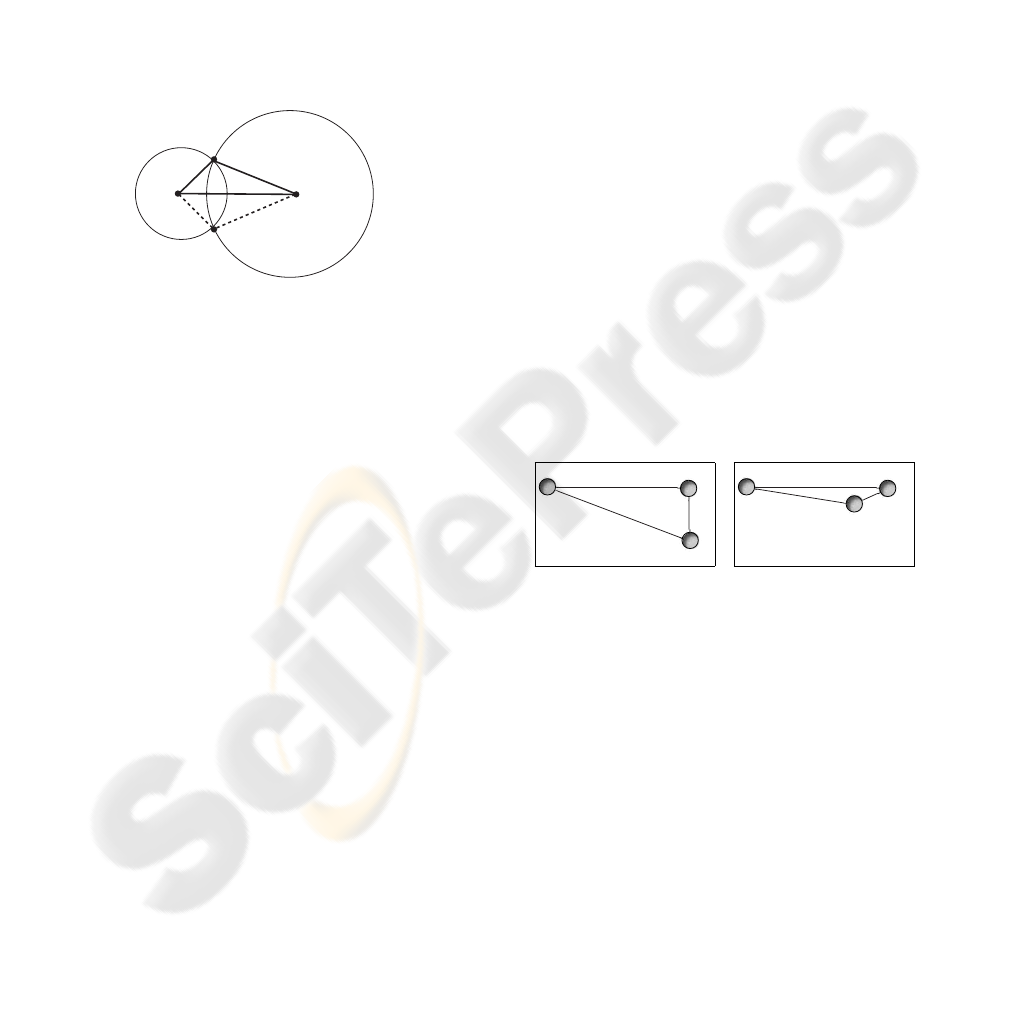
m
1
m
2
m
3
d
13
d
23
d
12
Figure 5: 2D Illustration of determination of third point us-
ing spheres.
Again, we add d
13
and d
23
to D. Now, that
three markers are configured, the rigid body can be
tracked. In order to enable robust tracking even if
several markers are occluded, e.g., by the device it-
self, further markers can be added.
4.1.2 Adding a Further Marker
We continue with a set of targets each consisting
of several markers, where the resulting distances are
stored in D. Let the current target contain i −1 mark-
ers. If the user wants to add the i-th marker to the
target, i − 1 distances from C have to be selected uni-
formly analogously to the procedure described in Sec-
tion 4.1.1. Furthermore, the new distances shall be el-
ements of C \ D, i.e., they are used neither within the
current target nor within another configuration. Again
the spheres surrounding the markers of the current tar-
get with radii determined by the corresponding dis-
tances have to intersect in one point at least. If one or
more intersection points exist, the desired distances
can be satisfied and the new marker can be inserted.
Otherwise, all distances have to be redefined, i.e., the
next distance from C is used as first distance in the
configuration and it is continued as described above.
An error degree is calculated by means of the sum
of the reciprocal values of the squares of differences
between the distances in D. This error degree in-
dicates how well the distances are distributed. The
aforementioned procedure is done in an optimization
step until the error degree is minimized, and the best
configuration for the target results.
If no intersection point exists for any distance of
C \ D, a compromise has to be accepted and also dis-
tances from D are allowed as long as no symmetrical
triangle constellations result. Thus, another marker
can be added although the resulting distances have
the potential to introduce ambiguities when track-
ing. However, since most marker positions have been
added using the described iterative way, our approach
provides a sufficient set of well-defined markers that
enhances tracking.
4.2 Example Configurations
4.2.1 Haptic Input Device
We have evaluated our approach for a hand-held inter-
action device, called haptic input device that is used
for multimodal VR-based interactions in several ap-
plication domains (Steinicke et al., 2005). The asso-
ciated target is illustrated in Figure 3 and Figure 6 (a).
The distances d
12
= 181.25mm, d
23
= 73.38, and
d
13
= 202.35 result from the marker positions as de-
scribed in Section 3.1. Since the minimal difference
between these distances is about 20mm, we have cho-
sen a distance threshold of ε = 9mm as explained in
Equation (4).
m
1
m
2
m
3
d
12
d
23
d
13
(a) original target
m
1
m
2
m
3
d
12
d
23
d
13
(b) proposed target
Figure 6: Configuration of markers for (a) original target
and (b) target generated by our approach. The markers have
been scaled for illustration purposes.
We have used our approach to redefine the po-
sition of marker m
3
, because we wanted to provide
the same starting distance d
12
in the resulting config-
uration. The algorithm produces the target depicted
in Figure 6 (b). The new position of marker m
3
is
(−17.2, 0.0, −124.1). Now, we can increase the dis-
tance threshold ε to 22mm, and the error degree could
be decreased to 0.001904 from 0.009276 for the orig-
inal distances.
4.2.2 Medarpa Display
Since the device in Section 4.2.1 is constrained to
only three markers, we have tested the approach also
VISAPP 2007 - International Conference on Computer Vision Theory and Applications
392

ments as combination of translations and rotations. In
both series we have used a distance threshold of 9mm.
Table 2: Results for original (HID-old) and proposed (HID-
new) target of HID for rotational movements in (A) inner,
(B) middle, and (C) outer third of interaction region.
device: HID-old HID-new
A abs/rel 326 / 82% 326 / 82%
B abs/rel 282 / 71% 307 / 77%
C abs/rel 231 / 58% 263 / 66%
Table 3: Results for original (HID-old) and proposed (HID-
new) target of HID for complex movements in (A) inner,
(B) middle, and (C) outer third of interaction region.
device: HID-old HID-new
A abs/rel 318 / 80% 326 / 82%
B abs/rel 249 / 62% 287 / 72%
C abs/rel 239 / 60% 274 / 69%
We have performed a similar analysis for the orig-
inal and proposed target of the MEDARPA display.
Therefore, we have taken 5 series with 2000 measure-
ments using a 2.5mm as well as 6mm distance thresh-
old.
While the original target has been correctly
tracked 1525 in average (76.5%), our proposed con-
figuration has reached in average 1662 correct track-
ing events (83.1%) when using the 2.5mm distance
threshold. For 6mm distance threshold, the results are
even better: 1529 in contrast to 1752 correct tracking
events for the original target respectively the proposed
configuration, which corresponds to an improvement
of 14%.
The results clearly show that our proposed con-
figuration de facto improves the tracking robustness.
In all regions of the interaction space, and with all
distance thresholds, our proposed configuration per-
formed better than the original rigid bodies.
6 DISCUSSION
In this paper we have proposed an approach to au-
tomatically generate rigid bodies for arbitrary MR
applications running with optical-based tracking sys-
tems. The approach determines the optimal configu-
ration for a target consisting of an arbitrary number
of markers with respect to the properties of the used
tracking system. We have tested the approach by re-
defining marker positions for existing devices. An
evaluation of the proposed configurations shows the
benefits of the approach; improvements of up to 20%
could be achieved without any modifications to the
tracking system. The considered devices have proven
their benefits for many applications in research as well
as industrial usage, and they have been revealed hav-
ing well-defined tracking properties. Nevertheless,
our simple approach enhances the tracking for them.
For the future we want to expand our system by
exporting a construction plan for the designer in or-
der to improve also the build process. This is due to
the fact that during our evaluation we figured out that
it is essential that the arrangement of markers allows
the cameras to see as many markers as possible si-
multaneously. A bad construction results in markers
occluding themselves, which yields reconstruction er-
rors. Furthermore, the size have the markers have to
be considered therefore. Moreover, the used camera
setup has to be taken into account since it has a major
impact on the tracking performance.
REFERENCES
A.R.T. (2006). http://www.ar-tracking.de. Advanced Real-
Time Tracking.
Azarbayejani, A. and Pentland, A. (1995). Camera Selfcal-
ibration from one Point Correspondence. Technical
Report Perceptual Computing Technical Report 341,
MIT Media Laboratory.
Bowman, D., Kruijff, E., LaViola, J., and Poupyrev, I.
(2004). 3D User Interfaces: Theory and Practice.
Addison-Wesley.
Davis, L. D., Hamza-Lup, F. G., and Rolland, J. P. (2004). A
Method for Designing Marker-based Tracking Probes.
In 3rd International Symposium on Mixed and Aug-
mented Reality, pages 120–129. IEEE and ACM.
Dorfm
¨
uller-Ulhaas, K. (2002). Optical Tracking - From
User Motion to 3D Interaction. PhD thesis, Technis-
che Universit
¨
at Wien.
Fakespace Systems (2006). http://www.fakespace.com.
Figueriredo, P. (2002). Automatic Learning and Detection
of Point-based Models. Master’s thesis, ZGDV, Darm-
stadt and Minho University, Portugal.
Hartley, R. and Sturm, P. (1997). Triangulation. Computer
Vision and Image Understanding, 68(2):146–157.
Kanbara, M., Yokoya, N., and I, H. T. . (2001). A Stereo
Vision-based Augmented Reality Registration with
Extendible Tracking of Markers and Natural Features.
In Proceedings of Conference on Computer Vision and
Pattern Recognition (CVPR2001), pages 1045–1048.
Kato, H. and Billinghurst, M. (1999). Marker Tracking
and HMD Calibration for a Video-based Augmented
Reality Conferencing System. In Proceedings of the
2nd International Workshop on Augmented Reality
(IWAR), page 85.
Ribo, M., Pinz, A., and Fuhrmann, A. (2001). A new
Optical Tracking System for Virtual and Augmented
VISAPP 2007 - International Conference on Computer Vision Theory and Applications
394

Reality Applications. In Proceedings of the IEEE
Instrumentation and Measurement Technical Confer-
ence, volume 3, pages 1932–1936.
Schwald, B. (2005). A Tracking Algorithm for Rigid Point-
Based Marker Models. In Proceedings of Interna-
tional Conferences in Central Europe on Computer
Graphics, Visualization and Computer Vision, pages
61–62.
Schwald, B. and Figueiredo, P. (2004). Learning of Rigid
Point-Based Marker Models for Tracking with Stereo
Camera Systems. In 1. Workshop der GI VR/AR
(Chemnitz), pages 23–34.
Steinicke, F., Ropinski, T., and Hinrichs, K. (2005). Multi-
modal Interaction Metaphors for Manipulation of Dis-
tant Objects in Immersive Virtual Environments. In
13th International Conference in Central Europe on
Computer Graphics, Visualization and Computer Vi-
sion, pages 45–48.
ZGDV (2005). MEDARPA: MEDical Augmented Reality
for PAtients. http://www.medarpa.de.
Zhang, Z. (2000). A Flexible New Technique for Camera
Calibration. IEEE Transactions on Pattern Analysis
and Machine Intelligence, 22(11):1330–1334.
GENERATING OPTIMIZED MARKER-BASED RIGID BODIES FOR OPTICAL TRACKING SYSTEMS
395
