
APPLICATION OF SPATIAL H
∞
CONTROL TECHNIQUE
FOR ACTIVE VIBRATION CONTROL OF A SMART BEAM
Ömer Faruk Kircali
STM Savunma Teknolojileri Mühendislik ve Ticaret A.Ş., Ankara, Turkey
Yavuz Yaman, Volkan Nalbantoğlu, Melin Şahin, Fatih Mutlu Karadal
Department of Aerospace Engineering, Middle East Technical University, Ankara, Turkey
Keywords: Assumed-Modes, Model Correction, Smart Beam, Spatial H
∞
Controller Design.
Abstract: This study presents the design and implementation of a spatial H
∞
controller for the active vibration control
of a cantilevered smart beam. The smart beam consists of a passive aluminum beam (507x51x2mm) and
eight symmetrically surface bonded SensorTech BM500 type PZT (Lead-Zirconate-Titanate) patches
(25x20x0.5mm). PZT patches are used as actuators and a laser displacement sensor is used as sensor. The
smart beam was analytically modelled by using the assumed-modes method. The model only included the
first two flexural vibrational modes and the model correction technique was applied to compensate the
possible error due to the higher order modes. The system model was also experimentally identified and both
theoretical and experimental models were used together in order to determine the modal damping ratios of
the smart beam. A spatial controller was designed for the suppression of the vibrations of the smart beam
due to its first two flexural modes. The designed controller was then implemented to experimentally
suppress the vibrations. This study also compared the effectiveness of a pointwise controller with the newly
developed spatial one.
1 INTRODUCTION
The vibration is an important phenomenon for the
lightweight flexible aerospace structures. Those
structures may be damaged under any undesired
vibrational load. Hence, they require a proper
control mechanism to attenuate the vibration levels
in order to preserve the structural consistency. The
usage of smart materials, as actuators and/or sensors,
has become promising research and application area
that gives the opportunity to accomplish the
reduction of vibration of flexible structures and
proves to be an effective active control mechanism.
The smart structure is a structure that can sense
external disturbance and respond to that with active
control in real time to maintain mission requirements
(Çalışkan, 2002). Active vibration control of a smart
structure requires an accurate system model of the
structure. Smart structures can be modeled by using
analytical methods or system identification
techniques using the experimental data (Meirovitch,
1986 and Nalbantoğlu, 1998). The system model of
a smart structure generally involves a large number
of vibrational modes. However, the performance
goals are mostly related to the first few vibrational
modes since their effect on structural failure is much
more prominent. Hence, a reduction of the order of
the model is required (Hughes, 1981 and
Moheimani, 1997). On the other hand, ignoring the
higher modes can affect the system behaviour since
directly removing the higher modes from the system
model perturbs the zeros of the system. Therefore,
in order to minimize the model reduction error, a
correction term, including some of the removed
modes, should be added to the model (Clark, 1997).
Today, robust stabilizing controllers designed in
respect of
H
∞
control technique are widely used on
active vibration control of smart structures. Yaman
et al. (2001 and 2003) showed the effect of
H
∞
controller on suppressing the vibrations of a smart
beam due its first two flexural modes. Similar work
is done for active vibration control of a smart plate,
322
Faruk Kircali Ö., Yaman Y., Nalbanto
˘
glu V., ¸Sahin M. and Mutlu Karadal F. (2007).
APPLICATION OF SPATIAL H∞ CONTROL TECHNIQUE FOR ACTIVE VIBRATION CONTROL OF A SMART BEAM.
In Proceedings of the Fourth International Conference on Informatics in Control, Automation and Robotics, pages 322-328
DOI: 10.5220/0001649403220328
Copyright
c
SciTePress

and the effective usage of piezoelectric actuators on
vibration suppression with
H
∞
controller was
successfully presented (Yaman, 2002).
Whichever controller design technique is
applied, the suppression should be preferred to be
achieved over the entire structure rather than at
specific points, since the flexible structures are
usually those of distributed parameter systems.
Moheimani and Fu (1998) and Moheimani et al.
(1997) introduced spatial
2
H and H
∞
norm
concepts in order to meet the need of spatial
vibration control, and simulation-based results of
spatial vibration control of a cantilevered beam were
presented. Moheimani et al. (1999) studied spatial
feedforward and feedback controller design, and
presented illustrative results. They also showed that
spatial
H
∞
controllers could be obtained from
standard
H
∞
controller design techniques. Halim
(2002) studied the implementation of spatial
H
∞
controller on active vibration control and presented
quite successful results. However his works were
limited to a beam with simply supported boundary
conditions.
This paper aims to present design and
implementation of a spatial
H
∞
controller on active
vibration control of a cantilevered smart beam.
2 THE SMART BEAM MODEL
The cantilevered smart beam model and its structural
properties are given in Figure 1 and Table 1,
respectively. The smart beam consists of a passive
aluminum beam (507mmx51mmx2mm) with
symmetrically surface bonded eight SensorTech
BM500 type PZT (Lead-Zirconate-Titanate) patches
(25mmx20mmx0.5mm). The beginning and end
locations of the PZT patches along the length of the
beam are denoted as r
1
and r
2
, respectively. The
patches are assumed to be optimally placed by
considering maximum strain characteristics
(Çalışkan, 2002). The parameters L, w, t, ρ, E, A, I,
d
31
denote length, width, thickness, density, Young’s
modulus, cross-sectional area, second moment of
area and piezoelectric charge constant; and the
subscripts b and p indicate the beam and PZT
patches, respectively. Note that, despite the actual
length of the beam is 507mm, the effective length
utilized in the study (i.e. the effective span of the
beam) reduces to 494mm since it is clamped with a
fixture.
Figure 1: The smart beam model used in the study.
Table 1: The properties of the smart beam.
Aluminum Passive Beam PZT
0.494
b
Lm=
0.05
p
Lm=
0.051
b
mw =
0.04
p
mw =
0.002
b
mt =
0.0005
p
mt =
3
2710 /
b
kg m
ρ
=
3
7650 /
p
kg m
ρ
=
69
b
GPaE = 64.52
p
E
GPa=
42
1.02 10
b
x
mA
−
=
42
0.2 10
p
x
mA
−
=
11 4
3.4 10
b
x
mI
−
=
11 4
6.33 10
p
Ixm
−
=
-
31
12
175 10 /
x
mVd
−
=−
The assumed-modes model of the smart beam
includes large number of resonant modes (Kırcalı,
2005). However, the control design criterion of this
study is to suppress only the first two flexural modes
of the smart beam. Hence, that higher order model is
directly truncated to a lower order one, including
only the first two flexural modes. The direct model
truncation may cause the zeros of the system to
perturb, which consequently affect the closed-loop
performance and stability of the system considered
(Clark, 1997). For this reason, a general correction
term
opt
i
k is added to the truncated model and the
resultant model (Kırcalı, 2005 and 2006) can be
expressed as:
250
22
13
()
(,) ()
2
opt
ii
Cii
ii
ii i
Pr
Gsr rk
ss
φ
φ
ξω ω
==
=+
∑∑
++
(1)
where general correction constant is [18]:
APPLICATION OF SPATIAL H∞ CONTROL TECHNIQUE FOR ACTIVE VIBRATION CONTROL OF A
SMART BEAM
323
222
22 22
21
11
ln
4
121
cci ii
opt
ii
ci
icciii
kP
ωωω ξω
ωω
ξωωωξω
⎧⎫
+−+
⎪⎪
=
⎨⎬
−−−+
⎪⎪
⎩⎭
(2)
and
[]
21
33
() ()
2
pi i
i
bbb p pp
Cr r
P
A
LAL
φφ
ρρ
′′
−
=
+
(3)
The nominal system model of the smart beam is
denoted by
(, )
C
Gsr. The geometric constant
31
()
ppppb
CEdwtt=+ is due to bending moment
of PZT patches exerted on the beam. The parameter
r defines the spatial variation along the longitudinal
axis and t is the time. The cut-off frequency of the
correction term is denoted by
c
ω
and the details of
all the parameters and the detailed derivation of the
equation (1) can be found in reference (Kırcalı,
2006).
Theoretical assumed-modes modeling does not
provide any information about the damping of the
system. Experimental system identification, on the
other hand, when used in collaboration with the
analytical model, helps one to obtain more accurate
spatial characteristics of the structure. The modal
damping ratios and more accurate resonance
frequencies were determined by spatial system
identification (Kırcalı, 2006) and the results are
given in Table-2:
Table 2: The resonance frequencies and modal damping
ratios of the smart beam.
1
ω
(Hz)
2
ω
(Hz)
1
ξ
2
ξ
6.742 41.308 0.027 0.008
3 SPATIAL H
∞
CONTROL OF THE
SMART BEAM
3.1 Controller Design
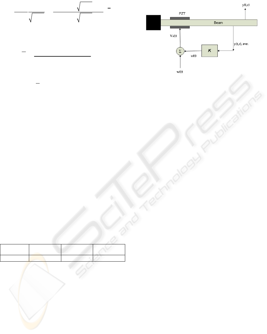
Consider the closed loop system of the smart beam
shown in Figure 2. The aim of the controller, K, is to
reduce the effect of disturbance signal over the
entire beam by the help of the PZT actuators.
Figure 2: The closed loop system of the smart beam.
The state space representation of the system
above can be shown to be (Kırcalı, 2006):
12
11 2
23 4
() () () ()
(,) ()() () () ()()
(, ) () () ()
L
xt Axt Bwt But
y
tr C rxt D rwt D rut
ytr Cxt Dwt Dut
=
++
=+ +
=+ +
(4)
where x is the state vector, w is the disturbance
input, u is the control input,
(, )ytr is the
performance output,
(, )
L
ytr
is the measured output
at location
0.99
L
b
rL= . The performance output
represents the displacement of the smart beam along
its entire body, and the measured output represents
the displacement of the smart beam at a specific
location A is the state matrix, B
1
and B
2
are the input
matrices from disturbance and control actuators
respectively, Π is the output matrix of error signals,
C
2
is the output matrix of sensor signals, Θ
1
, Θ
2
, D
3
and D
4
are the correction terms from disturbance
actuator to error signal, control actuator to error
signal, disturbance actuator to feedback sensor and
control actuator to feedback sensor respectively. The
disturbance
()wt is accepted to enter to the system
through the actuator channels, hence,
12
B
B
=
,
12
() ()
D
rDr= and
34
D
D
=
.
The state space form of the controller can be
represented as:
() () (, )
() () (, )
kkkkL
kk k L
x
tAxtBytr
ut Cx t Dytr
=
+
=+
(5)
such that the closed loop system satisfies:
[
)
2
2
0,
inf sup
KU
wL
J
γ
∈∞
∈∞
<
(6)
ICINCO 2007 - International Conference on Informatics in Control, Automation and Robotics
324
where
U
is the set of all stabilizing controllers and
γ
is a constant.
The spatial cost function to be minimized as the
design criterion is:
0
0
(, ) ( ) (, )
() ()
T
R
T
y
tr Qrytrdrdt
J
wt wtdt
∞
∞
∞
∫∫
=
∫
(7)
where
()Qr is a spatial weighting function that
designates the region over which the effect of the
disturbance is to be reduced and
J
∞
can be
considered as the ratio of the spatial energy of the
system output to that of the disturbance signal. The
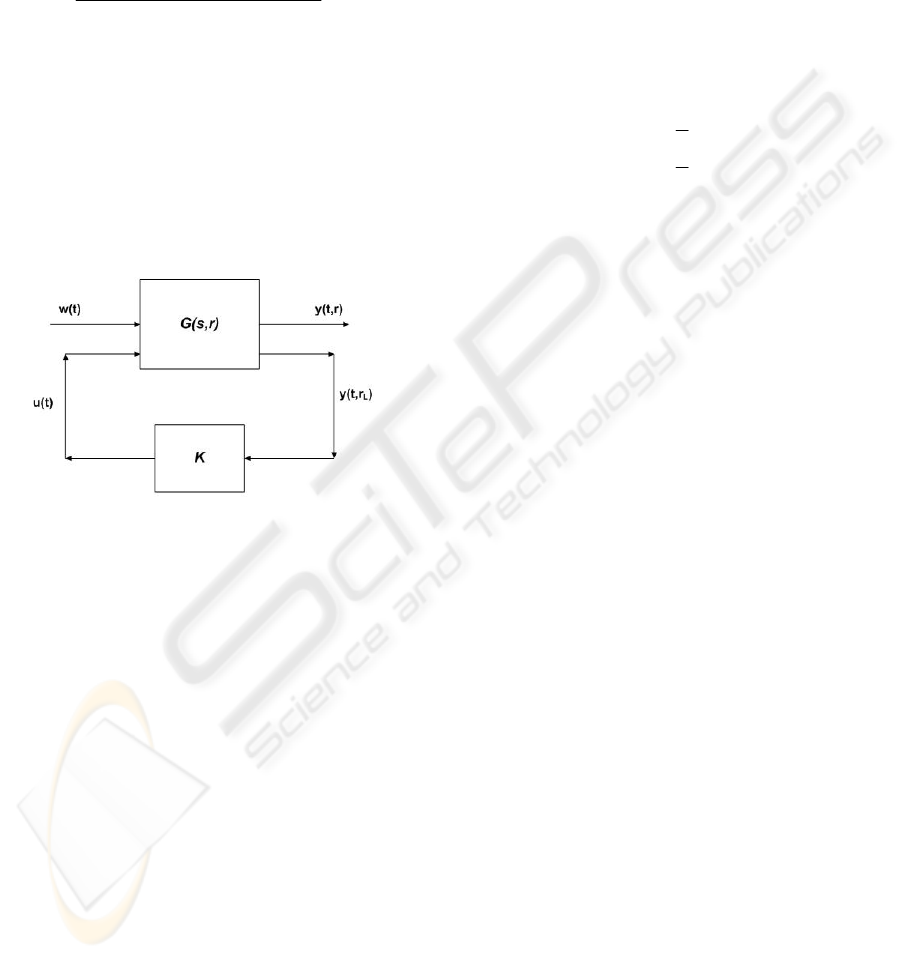
control problem is depicted in Figure 3.
Figure 3: The spatial H
∞
control problem of the smart
beam.
The spatial H
∞
control problem can be solved
by the equivalent ordinary
H
∞
problem (Moheimani
et.al, 2003) by taking:
00
(, ) () (, ) () ()
TT
R
y t r Q r y t r drdt y t y t dt
∞∞
=
∫∫ ∫
(8)
Hence, following the necessary mathematical
manipulations, the adapted state space representation
will be:
12
12
23 4
() () () ()
() () () ()
0
0
(, ) () () ()
L
xt Axt Bwt But
y
txt wt ut
ytr Cxt Dwt Dut
κ
=+ +
ΘΘ
Π
⎡⎤ ⎡⎤
⎡⎤
=+ +
⎢⎥ ⎢⎥
⎢⎥
⎣⎦
⎣⎦ ⎣⎦
=+ +
(9)
The derivation of equation (9) and the below
state space variables can be found in (Kırcalı, 2006)
as:
2
111
2
222
00 1 0
00 0 1
02 0
002
A
ωξω
ω
ξω
=
−−
−−
⎡
⎤
⎢
⎥
⎢
⎥
⎢
⎥
⎢
⎥
⎣
⎦
(10)
12
1
2
0
0
BB
P
P
==
⎡
⎤
⎢
⎥
⎢
⎥
⎢
⎥
⎢
⎥
⎢
⎥
⎣
⎦
(11)
1
2
1
()
()
0
0
T
r
r
C
φ
φ
=
⎡
⎤
⎢
⎥
⎢
⎥
⎢
⎥
⎢
⎥
⎣
⎦
,
1
2
2
()
()
0
0
T
L
L
r
r
C
φ
φ
=
⎡⎤
⎢⎥
⎢⎥
⎢⎥
⎢⎥
⎣⎦
(12)
50
12
3
50
34
3
()
()
opt
ii
i
opt
iL i
i
D
Drk
D
Drk
φ
φ
=
=
==
∑
==
∑
(13)
3/2
22 22
32 32
(0
00
)
b xx
xx
diag L
Π=
⎡
⎤
⎢
⎥
⎣
⎦
(14)
()
()
1/2
50
2
12
3
3
41
0
opt
bi
i
x
Lk
=
Θ=Θ=
∑
⎡
⎤
⎢
⎥
⎢
⎥
⎣
⎦
(15)
One should note that, the control weight,
κ
, is
added to the system in order to limit the controller
gain and avoid actuator saturation problem. In the
absence of the control weight, the major problem of
designing an
H
∞
controller for the system given in
equation (4) is that, such a design will result in a
controller with an infinitely large gain (Moheimani
et.al, 1999). In order to overcome this problem, an
appropriate control weight, which is determined by
the designer, should be added to the system. Since
the smaller
κ
will result in higher vibration
suppression but larger controller gain, it should be
determined optimally such that not only the gain of
the controller does not cause implementation
difficulties but also the suppressions of the vibration
levels are satisfactory. In this study,
κ
was decided
to be taken as 7.87x10
-7
. The simulation of the effect
APPLICATION OF SPATIAL H∞ CONTROL TECHNIQUE FOR ACTIVE VIBRATION CONTROL OF A
SMART BEAM
325
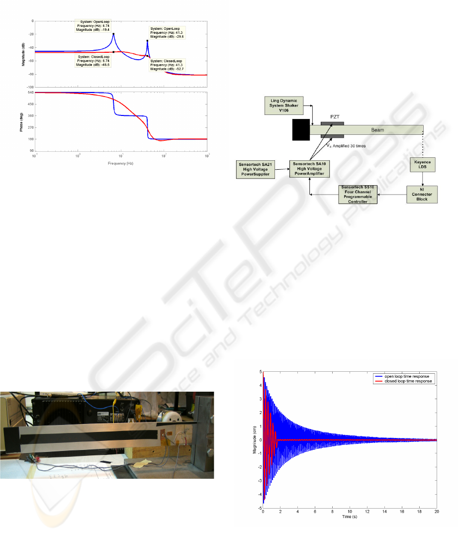
of the controller is shown in Figure 4 as a Bode plot,
and the frequency domain simulation is done by
Matlab v6.5.
Figure 4: Bode plots of the open and closed loop
frequency responses of the smart beam.
The vibration attenuation levels at the first two
flexural resonance frequencies were found to be 27.2
dB and 23.1 dB, respectively. The simulated results
show that the designed controller is effective on the
suppression of excessive vibrational levels.
3.2 Experimental Implementation
The smart beam of this study, shown in Figure 5,
consists of the PZT patches that are placed in a
collocated manner to have opposite polarity and
used as the actuators. A Keyence LB-1201(W) LB-
300 laser displacement sensor (LDS) is used as the
sensor. The closed loop experimental setup is shown
in Figure 6.
Figure 5: The smart beam used in the study.
The displacement of the smart beam at location
0.99
L
b
rL= was measured by using the LDS and
converted to a voltage output that was sent to the
SensorTech SS10 controller unit via the connector
block. The controller output was converted to the
analog signal and amplified 30 times by SensorTech
SA10 high voltage power amplifier before applied to
the piezoelectric patches. The controller unit is
hosted by a Linux machine, on which a shared disk
drive is present to store the input/output data and the
C programming language based executable code that
is used for real-time signal processing.
Figure 6: The closed loop experimental setup.
3.2.1 Free Vibration Suppression
For the free vibration control, the smart beam was
given an initial 5 cm tip deflection and the open loop
and closed loop time responses of the smart beam
were measured. The results are presented in Figure
7. Figure 7 shows that the controlled time response
of the smart beam settles nearly in 1.7 seconds.
Hence, the designed controller proves to be very
effective on suppressing the free vibration of the
smart beam.
Figure 7: Free vibration suppression of the smart beam.
ICINCO 2007 - International Conference on Informatics in Control, Automation and Robotics
326
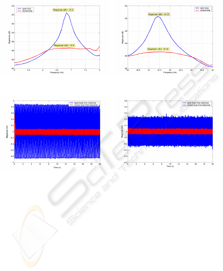
a) 5-8 Hz
b) 40-44 Hz
Figure 8: Bode magnitude plot of the open and closed loop systems.
a) 1
st
resonance b) 2
nd
resonance
Figure 9: Open and closed loop time responses of the smart beam under constant excitation at resonance frequencies.
3.2.2 Forced Vibration Suppression
The forced vibration control of the smart beam was
analyzed in two different configurations. In the first
one, the smart beam was excited for 180 seconds
with a shaker located very close to the root of the
smart beam, on which a sinusoidal chirp signal of
amplitude 4.5V was applied. The excitation
bandwidth was taken first 5 to 8 Hz and later 40 to
44 Hz to include the first two flexural resonance
frequencies separately. The experimental attenuation
of vibration levels were determined from the Bode
magnitude plots shown in Figure 8.a-b. The resultant
attenuation levels were found as 19.8 dB and 14.2
dB, respectively. In the second configuration,
instead of using a sinusoidal chirp signal, a constant
excitation was applied for 20 seconds at the
resonance frequencies again with a shaker. The
ratios of the maximum time responses of the open
and closed loop systems, shown in Figure 9.a-b, are
considered as absolute attenuation levels. Hence, for
this case, the attenuation levels at each resonance
frequency were calculated approximately as 10.4
and 4.17, respectively. Consequently, the
experimental results show that the controller is
effective on suppression of the forced vibration
levels of the smart beam.
3.3 Efficiency of the Controller
The efficiency of spatial controller in minimizing the
overall vibration over the smart beam was compared
by a pointwise controller that is designed to
minimize the vibrations only at point
0.99
L
b
rL= .
For a more detailed description of the pointwise
controller design, the interested reader may refer to
the reference (Kırcalı, 2006). The implementations
of the controllers showed that both controllers
reduced the vibration levels of the smart beam due to
APPLICATION OF SPATIAL H∞ CONTROL TECHNIQUE FOR ACTIVE VIBRATION CONTROL OF A
SMART BEAM
327
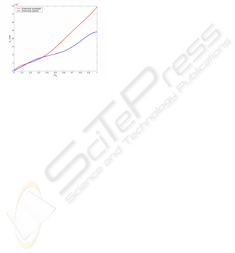
its first two flexural modes in comparable efficiency
(Kırcalı, 2006). On the other hand, the simulated
H
∞
norms of the smart beam as a function of r,
shown in Figure 10, showed that the spatial
H
∞
controller has a slight superiority on suppressing the
vibration levels over entire beam.
Figure 10: Simulated H
∞
norm plots of closed loop
systems under the effect of controllers.
4 CONCLUSION
This study presented the active vibration control of a
cantilevered smart beam. A spatial
H
∞
controller
was designed for suppressing the first two flexural
vibrations of the smart beam. The efficiency of the
controller was demonstrated both by simulation and
experimental implementations. The effectiveness of
the spatial controller on suppressing the vibrations of
the smart beam over its entire body was also
compared with a pointwise controller.
REFERENCES
Çalışkan T., 2002. Smart Materials and Their Applications
in Aerospace Structures. Ph.D. Thesis. Middle East
Technical University, Ankara, Turkey.
Meirovitch L., 1986. Elements of Vibration Analysis. The
McGraw-Hill Company.
Nalbantoğlu V., 1998. Robust Control and System
Identification for Flexible Structures. Ph.D. Thesis,
University of Minnesota, USA.
Hughes P.C., Skelton R.E., 1981. Modal Truncation for
Flexible Spacecraft, Journal of Guidance and Control,
vol.4, no.3.
Moheimani S.O.R., Pota H.R., Petersen I.R., 1997. Spatial
Balanced Model Reduction for Flexible Structures.
Proceedings of the American Control Conference,
3098-3102. Albuquerque, New Mexico.
Clark R.L., 1997. Accounting for Out-Of-Bandwidth
Modes in the Assumed Modes Approach: Implications
on Colocated Output Feedback Control. Transactions
of the ASME, Journal of Dynamic Systems,
Measurement, and Control, vol.119, 390-395.
Yaman Y., Çalışkan T., Nalbantoğlu V., Prasad E.,
Waechter D., Yan B., 2001. Active Vibration Control
of a Smart Beam, Canada-US CanSmart Workshop on
Smart Materials and Structures. 137-147, Montreal,
Canada.
Yaman Y., Ülker F. D., Nalbantoğlu V., Çalışkan T.,
Prasad E., Waechter D., Yan B., 2003. Application of
H
∞
Active Vibration Control Strategy in Smart
Structures. 3rd International Conference on Advanced
Engineering Design. Paper A5.3, Prague, Czech
Republic.
Yaman Y., Çalışkan T., Nalbantoğlu V., Ülker F. D.,
Prasad E., Waechter D., Yan B., 2002. Active
Vibration Control of Smart Plates by Using
Piezoelectric Actuators, 6th Biennial Conference on
Engineering Systems Design and Analysis, Paper
APM-018. Istanbul, Turkey.
Moheimani S.O.R, Fu M., 1998. Spatial H
2
Norm of
Flexible Structures and its Application in Model Order
Selection. International Proceedings of 37th IEEE
Conference on Decision and Control, Tampa Florida,
USA.
Moheimani S.O.R., Pota H.R., Petersen I.R., 1997. Spatial
Balanced Model Reduction for Flexible Structures,
Proceedings of the American Control Conference, pp.
3098-3102, Albuquerque, New Mexico.
Moheimani S.O.R., Petersen I.R., Pota H.R., 1999.
Broadband Disturbance Attenuation over an Entire
Beam, Journal of Sound and Vibration, 227(4): 807-
832.
Halim D., Moheimani S.O.R., 2002. Experimental
Implementation of Spatial H
∞
Control on a
Piezoelectric Laminate Beam. IEEE/ASME
Transactions on Mechatronics, vol.7, no: 3.
Kırcalı Ö.F., Yaman Y., Nalbantoğlu V., Şahin M.,
Karadal F.M., 2005. Spatial System Identification of a
Smart Beam by Assumed-Modes Method and Model
Correction. Kayseri VI Aeronautics Symposium.
Nevsehir, Turkey (in Turkish).
Halim D., 2002. Vibration Analysis and Control of Smart
Structures, PhD. Thesis,. School of Electrical
Engineering and Computer Science, University of
Newcastle, Australia.
Kırcalı Ö.F., 2006. Active Vibration Control of a Smart
Beam: a Spatial Approach, M.S. Thesis, Middle East
Technical University, Ankara, Turkey.
Moheimani S.O.R., Halim D., Fleming A.J., 2003. Spatial
Control of Vibration. Theory and Experiments, World
Scientific Publishing Co. Pte. Ltd.
ICINCO 2007 - International Conference on Informatics in Control, Automation and Robotics
328
