A NEW UART CONTROLLER
Nonel Thirer
HIT, Holon Institute of Technology, Holon, Israel
Radu Florescu
ORT Braude College, Carmiel, Israel
Keywords: UART, Hamming Code, FPGA.
Abstract: The paper presents a new UART (Universal Asynchronous Receiver/Transmitter) controller which differs
from traditional UARTs by providing a user defined data path width of 8 ,16, or 32 bits; by using a one bit
error detection and correction algorithm (Hamming); and by permitting a large range of baud rates without
the need of adding chips. By using the Hamming code, the communication throughput is increased,
especially when a large data path width is defined. This new UART better responds to modern
microprocessors’ requirements, and was successfully implemented in an FPGA circuit.
1 INTRODUCTION
UARTs and USARTs (Universal Synchronous
Asynchronous Receiver/Transmitter) devices are
parallel-to-serial interfaces widely used in modern
computer systems. They appear both as discrete
components, as well as a part of a VLSI chip, or
implanted as an intrinsic part of some
microcontrollers and microprocessors.
In most UARTs and USARTs the parallel data
path width is a maximum 8 bits. A detection error
procedure, based on a parity bit, permits only to
detect a one bit error. Also, for correction, an upper
communication layer must be used (and data must
be resent). In edition, the baud rate is constrained by
the value of the external clock and an auxiliary
programmable counter must be used to obtain
various baud rates.
By improving these features, the new UART will
be most suitable to modern microprocessors which
have a large data path and a fast transmision rate.
2 THE NEW UART
This paper presents the possibility to improve the
features of the traditional UARTs, by widening the
data path; by adding a one bit error correction
procedure; and by providing a larger range of baud
rates.
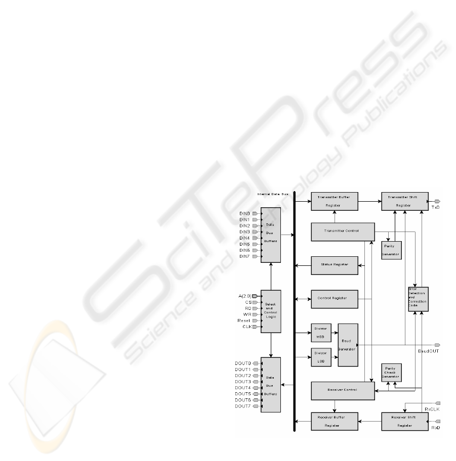
Figure 1: The UART block scheme.
The principial block scheme is presented in fig.1. (note:
only 8 bits of parallel data are presented in this figure).
354
Thirer N. and Florescu R. (2007).
A NEW UART CONTROLLER.
In Proceedings of the Fourth International Conference on Informatics in Control, Automation and Robotics, pages 354-356
DOI: 10.5220/0001623703540356
Copyright
c
SciTePress

2.1 Data Encoding
The algorithm that encodes the data according to the
Hamming code (Peterson, 1992) is simple:
- all bit positions that are powers of two (positions:
1, 2, 4, 8 and so on) are used as parity bits (P1, P2,
P3, P4 and so on);
- all other bit positions (positions 3, 5, 6 and so on)
are reserved for the data itself (D0, D1, D2 and so
on)
Thus the data stream will be:
- P1, P2, D0, P3, D1, D2, D3, P4, D4, D5, D6, D7
for an 8 bits data;
- P1, P2, D0, P3, D1, D2, D3, P4, D4 … D10, P5,
D11 … D15 for a 16 bits data;
- P1, P2, D0, P3, D1, D2, D3, P4, D4 … D10, P5,
D11 … D25, P6, D26 … D31 for a 32 bits data.
Adding a start bit (‘0’) and a stop bit (‘1’), a total
of 14 bits are necessary to transmit/receive a byte,
23 bits to transmit/receive a word, and 40 bits to
transmit/receive a double word.
To transmit/receive the 8 bits data, a “classical”
UART (working with only one stop bit) uses 3
supplementary bits (a 37.5% overhead).
In the proposed UART, the total number of
supplementary bits will be 6 for an 8 bits data (a
75% overhead), 7 for a 16 bits data (44%), but only
8 for a 32 bits data (only a 25% overhead).
Thus, to transmit a byte, the classical UART
must transmit only 11 bits and the proposed UART
must transmit 14 bits, decreasing the communication
throughput. But, to transmit a double word, the
classical UART must transmit 44 bits, whereas the
proposed UART transmits only 40 bits, and
therefore increasing the communication speed.
This joins another feature of the new UART
which ups communication speed, which is its error
self-correction ability (which saves the need for
resending data).
2.2 Error Detection and Correction
When a transmission error occurs, the traditional
UART can only detect it. Correction must be made
at a superior level of communication, and involves
resending the data, a lengthy process.
It is to be noted that this is typical also to other
communication protocols, such as the very popular
USB communication standard, which uses a CRC
method to detect the transmission error – a Not
Acknowledge (NAK) response of the receiver if an
error will appear, will also require to repeat the
transmission.
In contradiction, the new UART’s multiple
parity bits mechanism, as laid in the Hamming
Code, allows it to correct, by itself, every single
error. In this manner, no superior level of
communication is required. Moreover, using a
pipeline procedure, the receiver can correct the error
in parallel with a new data receiving process, thus
the communication throughput is not affected by the
eventual transmission errors (Thirer, 2006).
It is also notable that Hamming code also allows
detecting double errors, but can only correct a single
error. Meaning, the method of error correction is not
best suited for errors that come in bursts, but to
situations in which errors are randomly occurring
(and those are the most common in UART).
2.3 Baud Rate
To provide a large range of baud rates, a
programmable 16 bits counter is included in the
UART.
Thus the UART is able to work with various
baud rates, from the transmission clock value
TXCLK to TXCLK / 65536 without additional
circuits.
3 AN FPGA IMPLEMENTATION
This UART was successfully implemented and
tested in an ALTERA CYCLONE EP1C6Q240C8
FPGA chip
The UART controller includes a transmitter unit,
a receiver unit and an internal counter.
The user can select the data path width (8, 16 or
32 bits), the error control method (parity bit or
Hamming code) and also the baud rate (by the value
of the counter acting as a clock divider ).
Fig. 2 presents the state machine to generate and
transmit the serial data stream by using the parity
control bit or by using the Hamming control bits.
For generate the parity bits, a XOR based
scheme was implemented in the transmitter unit.
Evidently, the use of separate schemes for every
parity bit will increase the speed, by a parallel
computation, but a cheaper UART implementation
can use a single parity generator scheme for a serial
computation of the P1, P2, …P6 bits.
Fig. 3 presents the state machine for the receiver
unit, including the parity check and the Hamming
error check and fix.
Fig. 4 presents the block scheme of the receiver
unit.
In the receiver unit, the parity check and fix
section includes a parity generator (like the parity
circuit of the transmitter unit) a six bit comparator
(to check the received parity bits) and an adder
A NEW UART CONTROLLER
355
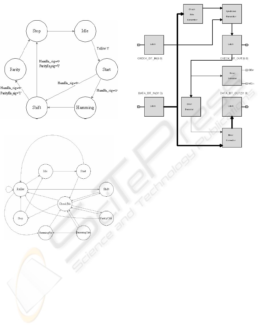
circuit to compute the position of the erroneous bit(
if occurs). To fix this bit a simple inverter is used.
Figure 2: The Transmit Data Unit State Machine.
Figure 3: The Receiver Unit State Machine.
Figure 4: The Receiver Unit block scheme.
4 CONCLUSIONS
An improved UART controller is presented,
compatible with the modern microprocessors and
microcontrollers.
The implementation of an error correction
algorithm permits to increase the transmit rate. The
communication throughput is not affected by the
eventual transmission errors.
For the new 64 bit microprocessors, a 64 bit data
path can be easily implemented in this UART, by
adding only a single Hamming parity bit.
REFERENCES
Durda, F., 1996. Serial and UART Tutorial. In
http://jamesthornton.com/freebsd/articles/serial-uart/
Peterson, Wesley W., Weldon Jr, E.J , 1992, Error
Corecting Codes, The MIT Press, 2
nd
Edition
Thirer, N., Efron, a.o. U., 2006. Improvement of FPGA
Pipelines Implementation. In PROC of SPIE Conf,
“Optical Engineering and Instrumentation” (paper
#6294-37)
ICINCO 2007 - International Conference on Informatics in Control, Automation and Robotics
356
