
Path Location Register for Next-Generation
Heterogeneous Mobile Networks
Theodore Zahariadis
1
, Stamatis Voliotis
2
1.
Ellemedia Technologies/Bell Labs, 223 Syggrou Av.,Athens, GR-171 21 Greece
2.
Technical Educational Institute of Chalkida, Psahna, Greece
Abstract. Deployment of a global all IP wireless/mobile network is not a
straightforward decision. Heterogeneous mobile networks combined with
wireless “hot-spot” locations seams to be one of the most realistic early
deployments. Commercial public wireless LAN solutions however offer
proprietary location management capabilities compared to the traditional
cellular networks. The increasing demands for heterogeneous services
necessitate fast and efficient location management mechanisms that allow the
future personal communication service network to locate mobile users roaming
across different systems. This paper introduces and analyzes a Path Location
Register (PLR) mechanism for Location Management that reduces significantly
the cost of mobile terminal location update and paging. The performance
evaluation of the PLR scheme demonstrates its effectiveness in next generation
heterogeneous mobile networks.
1. Introduction
Forth generation (4G) all-IP networks are expected to provide a substantially wider
and enhanced range of interactive multimedia services. Terminal and personal
mobility will enable users to access their personal profile, independently of the
terminal type or the point of attachment to the network. However, deployment of a
global all-IP wireless/mobile network is not a straightforward decision, due to
technical and economical issues. A phased approach, integrating heterogeneous
2G+/3G and wireless LAN technologies on “hot-spot” locations, appears to be one of
the most realistic early deployment approaches. In order to facilitate global
connectivity with maximum bandwidth and minimum cost a variety of mature
wireless/ mobile technologies can be considered. In the local area, the Wireless LAN
(WLAN) is a well-established and expanding market, with superior bandwidth
compared to any cellular technology and supported by international standards (i.e.
IEEE 802.11 a, b, g, e, ETSI HiperLAN I & II, Bluetooth). Regarding the wide area
network, mature cellular standards are already deployed (i.e. GPRS, EDGE, IS-95,
CDMA). In case of absence of cellular network, satellite links can fulfill the
requirement for worldwide coverage [1].
Connectivity at the physical layer is mandatory, but this is only a part of the
problem. The increasing demand for heterogeneous services necessitates fast and
efficient location management mechanisms that allow the future personal
Zahariadis T. and Voliotis S. (2004).
Path Location Register for Next-Generation Heterogeneous Mobile Networks.
In Proceedings of the 3rd International Workshop on Wireless Information Systems, pages 142-151
DOI: 10.5220/0002670301420151
Copyright
c
SciTePress

communication service (PCS) network to locate mobile users roaming across different
systems. Generally a location management scheme contains two processes: location
update and paging. In case of uniform systems, many location management schemes
have been proposed and evaluated for both cellular systems [2][3] and computer
oriented networks [4][5]. In case of heterogeneous PCS systems, the registration, call
delivery and handset identity are discussed in [8], while methods for enhancing the
network’s location management in multitier (GSM, IS-95, IS-54) systems have been
proposed in [6][7]. Roaming across systems imposes a significant increase in
signaling traffic. However, 3G+ and 4G Mobile Networks will not be voice-centric,
but QoS aware data centric; thus specific location management algorithms that take
into account parameters like QoS, call and packets loss, paging delay should be
considered. In this paper, a Location Management scheme for heterogeneous
networks is analyzed and evaluated. The scheme is based on the introduction of a
layer of Path Location Register (PLR) servers along with roaming and paging
algorithms that handle mobile terminals mobility on local or regional base. The
performance evaluation of the proposed scheme demonstrates its effectiveness in
heterogeneous next generation mobile networks.
2. All-IP heterogeneous network architecture
In a multitier system consisting of heterogeneous wireless technologies, different
networks are combined in order to cover a specific geographical area. Each network
may comply with different specifications and standards, and encompass different
number of cells, while cell overlapping is expected. Cells’ physical or logical
diameters and transmission characteristics (e.g. bandwidth, maximum number of
terminals, connection set-up time, call tear-down probability) may vary. Even in the
same tier, parameters like the signaling messages sequence and format, the
authorization rights etc. may differ.
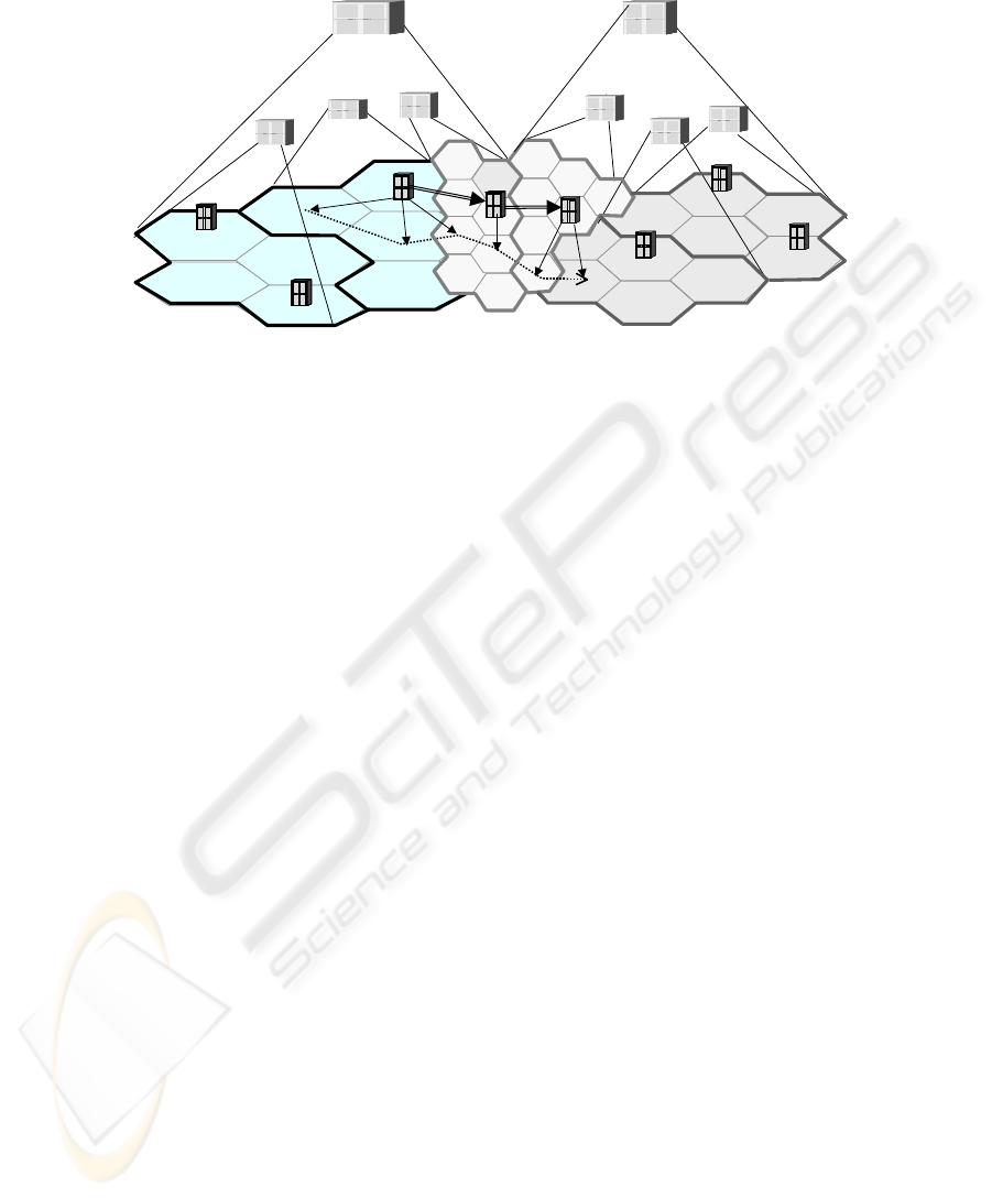
For example in Fig. 1, three different networks are shown. A mobile terminal
(MT) may roam between cells of the same tier or between cells of different networks.
In case MT enters an area where cells overlap, it may select to handoff to the newly
entered network or remain attached to the previous one. The handover selection may
be based on the networks’/ cells’ characteristics or on the network handoff/location
management overheads. As shown, an extended Home Location Register (HLR+)
may control a number of different networks either of the same or of different types.
When a terminal roams between cells of the same type, it may or may not change
servicing area (and Visiting Location Register, VLR). For example, when the MT
roams from cell A to cell B, it does not change servicing area or network. When it
roams from cell B to C, it changes cell, servicing area and network; thus it changes
from VLR2 to VLR3. Moreover, when the terminal roams from cell D to E, it
changes VRL and HLR+, though it does not roam to a new wireless network
technology.
143

Network A
Network C
VLR 3
B
B
C
C
E
E
F
F
A
A
D
D
HLR+ 1HLR+ 1 HLR+ 2HLR+ 2
VLR 1
VLR 2
VLR 6
VLR 5
VLR 4
Network B
Fig. 1. Network Hierarchy Architecture
The problem in the above architecture is that the respective VLRs and HLR+ have
to be updated every time the MT roams to a new cell. This heavily increases the
signaling overhead especially in case the MT moves back and forth in the
surroundings of a servicing area, the so-called “ping-pong” effect. Apart from the
extensive signaling, the ping-pong roaming effect causes additional overheads, due to
the locality of the IPv4 addresses. Mobile IP and various alternatives and extensions
[8] aim to face the problem of mobility in both wireless and mobile environment, but
none has yet managed to take into account the mobility management, the QoS
requirements and the heterogeneity of the network, while other (i.e. HAWAII [9],
Cellular IP, UniWA [10]) use layer-3 signaling, increasing the handover latency and
originating significant packet losses.
3. Path Location Register
Aiming to solve efficiently the mobility problem in heterogeneous all-IP
wireless/mobile networks, we introduce a Path Location Register (PLR) management
scheme. The scheme includes an intersystem roaming and a paging algorithm.
In the proposed schema, a PLR servers’ layer is introduced in lower hierarchy from
the VLR that trail the MT when roaming, primarily on the boundaries between IP
networks. Terminals are assumed to be multi-band/multi-standard devices able to gain
connectivity either in macrocell or microcell environment. Each MT is permanent
associated with an extended HLR+. When the MT moves to a visiting network, it is
temporary assigned to a VLR, which updates the HLR+ for the terminal position. In
parallel, a PLR is also informed in order to keep track of the MT movements in local
basis. When the MT roams to a neighboring cell, the PLR may continue to route
traffic to the terminal either directly or via a PLR that is “closer”. The distance
between the terminal and the PLR may be defined as a function of the cell
characteristics (diameter, load, current number of terminals, QoS capabilities), the
terminal motion (speed, direction) or the call requirements (bandwidth, handoff
sensitivity, error correction). As the traffic is routed via the PLR, it can easily track
the MT and inform the neighboring PLR when the MT is approaching the servicing
area boundaries. When the MT roams to a cell or network of different type, the PLR
may handle additional issues, such as air interface compatibility, user/terminal
authentication, billing etc.
144
Network A
Network C
VLR 3
B
B
C
C
E
E
F
F
A
A
D
D
HLR+ 1HLR+ 1 HLR+ 2HLR+ 2
VLR 1
VLR 2
VLR 6
VLR 5
VLR 4
Network B
PLR-2
PLR-3
PLR-4
PLR-5
PLR-6
PLR-8
PLR-1
PLR-7
Fig. 2. Path Location Register Network Architecture
For example in Fig. 2, when the MT is located in cell A, it is also assigned to
HLR+ 1, VLR1 and PLR3. The same PLR keeps tracking the MT and routes traffic
until it reaches position C. As the networks A and B overlap, the MT may decide to
avoid roaming to Network B, but continue to communicate via PLR3. Nevertheless
the PLR4 is informed that the terminal has entered its servicing area, so according to
MT move, call requirements and network load, the PLR4 performs a preliminary
resource allocation in the neighboring cells. For instance if Network B is a public
Wireless LAN, the MT may select to keep the cellular interface active, while in
parallel the MT’s 802.11 interface and the network access node are prepared for a
potential handoff. In this way, if the MT returns to cell B no actual roaming is
performed, while if the MT roams to cell D, traffic is routed via PLR4. As PLR3 and
PLR4 belong to the same HLR+, they are considered “close by”; thus the VLR layer
is not informed at all, while the roaming is handled in PLR layer. According to
network ownership, these PLRs may be considered “close by” or “remote”. For
example, if the MT roams to cell E, traffic may be routed via direct links between
PLR3, PLR4 and PLR5, or the VLR and HLR+ hierarchy may be informed. The
drawback is that inter-PLR links increase the paging delay; thus thresholds in PLR
links paths are introduced.
145
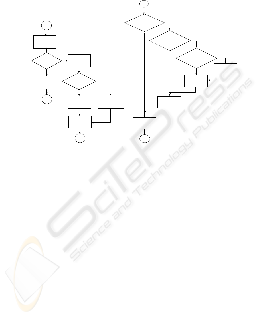
X
Start
Yes
X
Calculate
PLR distance
Create a new
PLR path
PLR distance < Dp
Locate an
appropriate PLR
No
Yes
No
Inter-PLR path
length < D
IP
Creat e a new
Inter-PLR link
Create a new
PLR path
Update the VLR &
the HLR servers
Start
Yes
Is the called terminal
at the same PLR?
No
Is the called terminal
connected via an
inter-PLR link?
Yes
Follow the path
to the PLR
Page/Traffic
Route Directly
X
Follow the inter-
PLR link(s)
No
Yes
Is the called terminal
at the same
VLR/HLR?
Follow the path
to the VLR/PLR
No
a) PLR Roaming Algorithm b) PLR Paging Algorithm
Fig. 3. PLR Roaming Algorithm & PLR Paging Algorithm
In Fig. 3a the PLR roaming algorithm flow diagram is shown. For simplicity we
assume that there are no ownership, deployment or other issues, but the decision for
handoff is based only on performance criteria. As shown two thresholds are
measured: the D
P
, which is the maximum allowed distance between the MT and the
PLR and the D
IP,
which is the maximum length of the inter-PLR link. In classical
roaming algorithms, the VLR and the HLR+ should know the path to the terminal in
order to be able to route incoming calls and packets. This would result in many
routing entries updates, and many VLR and HLR+ signaling messages. In order to
minimize this overhead in the PLR scheme, we postpone the HLR+ update and treat
the roaming in local or regional layer. When a terminal roams to a new servicing area
the distance between the servicing PLR is checked. If it is less than the maximum
distance D
P
a new PLR route is created and no further actions take place. If the
maximum distance is exceeded, an “appropriate” new PLR server is located and an
inter-PLR link is created. Many criteria can be involved in the selection of the new
PLR: the distance from the terminal, the location, the terminal’s call and connection
requirements, the PLR load, or even statistical measurements and profiles may be
involved. For simplicity reasons each PLR has a list of neighboring PLR’s, so
searching is efficient. When creating the inter-PLR link, an optimal routing algorithm
may be invoked to check if the path has some cycles, or if a path between the PLR
servers already exists. If no “appropriate” PLR can be found, the VLR and HLR+ are
informed and the complete path to the terminal is refreshed.
146

Due to PLR roaming algorithm, the paging algorithm is also modified.
Additionally to direct indexing from HLR+ to MT, we have to trace the PLR and the
inter-PLR links if exist. As shown in Fig. 3b, the paging/traffic routing algorithm
starts from the PLR that the MT is located, and follows a bottom up approach. If the
intermediate layers fail to locate the MT in the servicing area, the HLR+/VLR layer is
reached and normal routing is followed. The paging delay is the overhead, the PLR
has to pay for benefit of less signaling at the roaming phase. However, if the paging is
not a critical factor, the longer the inter-PLR link chain, the largest saving could be
obtained. In some cases due to the heterogeneity of the network, the PLR
paging/traffic routing algorithm may be even more efficient than normal paging, as it
assumes larger servicing areas and omits searching in adjacent network systems.
The main benefit of the PLR scheme is that it significantly reduces the signaling
cost and the set-up overhead caused by the intersystem roaming. Traffic routing is not
modified, but the network traces the MT as it moves from cell-to-cell and from
network-to-network and adds or drops links and paths accordingly. Moreover,
roaming is handled locally in each servicing area, so the ping-pong effect is omitted.
Another advantage of the PLR scheme is that the additional layer of PLR servers does
not affect the original database architecture. The additional hardware and
communication links between PLRs can be safely balanced by reducing the number
of VLR servers in an area.
4. Performance Analysis
In this section we adapt the analytical model of [12] in order to evaluate the
performance of the proposed PLR scheme. Lets assume that the calls towards a
terminal have mean rate λ and the mean time a terminal is located in the servicing
area of a PLR is 1/µ. Then the terminal call-mobility ratio (CMR) in this area would
be CMR=p=λ/µ. If the PLR algorithm is not applied, the HLR+ and the VLR servers
will be informed every time the terminal roams to a new cell. Otherwise it will be
informed each time the path to the terminal exceeds a maximum distance of D
PLR
=
D
IP
+ D
P
, where D
IP
is the length of inter-PLR links and D
P
is the distance between
the last PLR and the terminal. If we assume that by average the terminal changes PLR
every T
P
moves and the D
IP
has a length of T
IP
links, the D
PLR
distance will by
average result after T
P
T
IP
moves assuming that no circles are measured.
If the user roams to n different PLR servers between two calls the HLR+ will be
updated N
HLR
=
⎥
⎦
⎥
⎢
⎣
⎢
PIP TT
n
times. The number of PLR routing table updates will be
N
PLR
=
⎥
⎦
⎥
⎢
⎣
⎢
IPT
n
-
⎥
⎦
⎥
⎢
⎣
⎢
PIP TT
n
, while the number of inter-PLR routing table updates will be
N
IPLR
= n -
⎥
⎦
⎥
⎢
⎣
⎢
IPT
n
. The expected cost for the PLR roaming algorithm will be:
{}
∑
∞
=
⋅+⋅+⋅=
0
)(
n
rPLRPLRIPLRIPLRHLRHLR
ROAM
npCNCNCNC
(1)
147

where C
HLR
is the cost of an HLR+ update, C
IPLR
the cost for inserting/updating an
inter-PLR link, C
PLR
is the cost for updating a routing entry, and p
r
(n) is the
probability that n different PLR servers are crossed within two calls. After the HLR+
is updated, the length of the path to the terminal consists of
L
PLR
=
⎥
⎥
⎥
⎥
⎦
⎥
⎢
⎢
⎢
⎢
⎣
⎢
⎥
⎦
⎥
⎢
⎣
⎢
−
IP
PIP
PIP
T
TT
TT
n
n
(2)
PLR links (entries at the PLR routing tables), and
L
IPLR
= n -
⎥
⎦
⎥
⎢
⎣
⎢
PIP TT
n
T
IP
T
P
– N
IPLR
T
IP
(3)
Inter-PLR links. If C
P
is the cost for a direct terminal paging, O
PLR
is the overhead to
follow an entry in the PLR routing table and O
IPLR
the relevant overhead for the inter-
PLR roaming, the overall cost for the PLR paging algorithm will be
{}
p
n
rIPLRIPLRPLRPLRPAGE
CnpOLOLC ++⋅=
∑
∞
=
⋅
0
)(
(4)
In order to evaluate the p
r
(n), we assume that the mean rate λ of the call arrivals is
a Poison distribution and the interval between two PLR roaming instances is a random
variable, which for simplicity has a general density function described by a Gamma
distribution with mean 1/µ. The Laplace transform of the Gamma distribution is
p
ff
rr CC
+
=⎯⎯→⎯
=
⎟
⎟
⎠
⎞
⎜
⎜
⎝
⎛
+
=
1
1
)(
1
)(
λ
γ
γµλ
γµ
λ
γ
where p=λ/µ. For simplicity we have assumed an exponential distribution, thus γ=1. It
can be shown that (1) and (4) are equal to
1)1(1)1( −+
−
+
−+
−
+=
PIPIP TT
IPLRr
T
IPLRPLRIPLR
ROAM
p
CC
p
CC
p
C
C
(5)
+
−+
−+=
1)1(
PIP
PIPIPLRIPLR
pPAGE
TT
p
TTO
p
O
CC
]1)1][(1)1[(
]1)1()1)[((
−+−+
−++−+−
+
IPPIP
P
IP
P
PIP
PLRIPPLR
T
p
TT
p
T
T
pT
TT
pOTO
(6)
Without the PLR algorithm the overall cost for maintaining the location information
and page the terminal is:
P
r
C
P
C
C +=
(7)
While the overall cost for the PLR architecture is
148
PAGEROAMPLR CCC +=
(8)
The roam (G
ROAM
), page (G
PAGE
) and overall (G
Total
) gains are
r
ROAM
ROAM
C
C
G = ,
p
PAGE
PAGE
C
C
G =
,
C
C
G
PLR
TOTAL
=
(9)
From (1)-(9), the
TOTALG
can be evaluated. If we assume that C
IPLR
= 2O
IPLR
and
C
PLR
= 2O
PLR,
from (8)-(9), we can depict the PLR roam, page and total gains as a
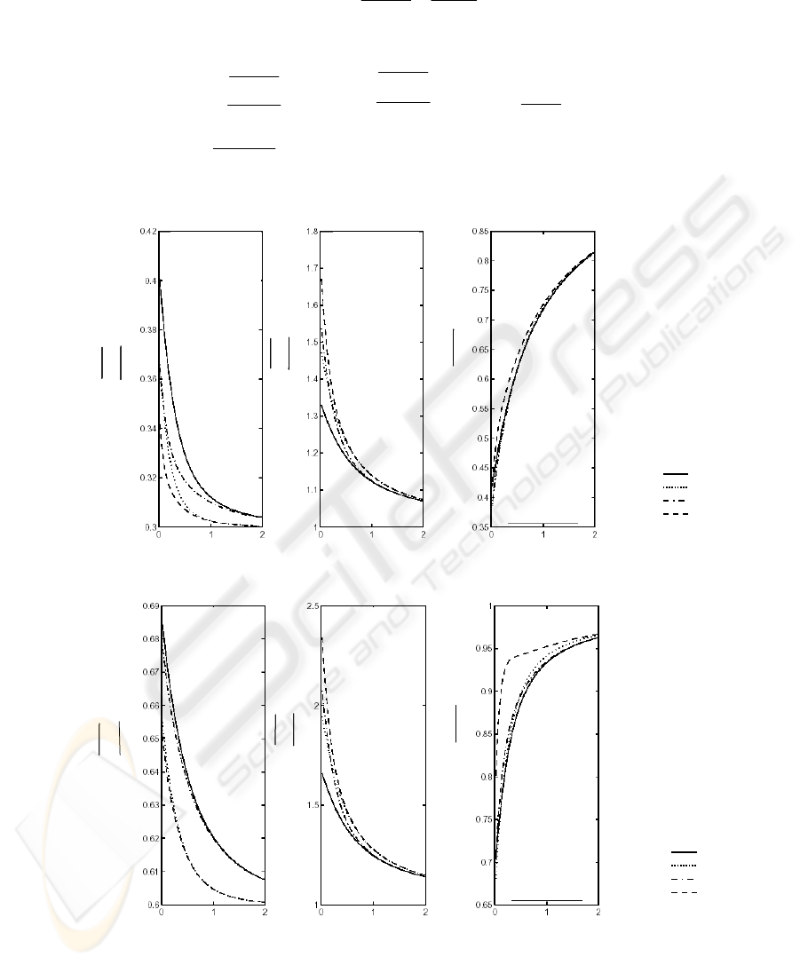
function of terminal Call-Mobility Ratio (p).
T
P
=2, T
IP
=4
T
P
=2, T
IP
=6
T
P
=4, T
IP
=4
T
P
=4, T
IP
=6
p
r
ROAM
ROAM
C
C
G
=
r
ROAM
ROAM
C
C
G
=
p
PAGE
PAGE
C
C
G
=
p
PAGE
PAGE
C
C
G
=
pp
C
C
G
TOTAL
=
C
C
G
PLR
TOTAL
=
T
P
=2, T
IP
=4
T
P
=2, T
IP
=6
T
P
=4, T
IP
=4
T
P
=4, T
IP
=6
T
P
=2, T
IP
=4
T
P
=2, T
IP
=6
T
P
=4, T
IP
=4
T
P
=4, T
IP
=6
p
r
ROAM
ROAM
C
C
G
=
r
ROAM
ROAM
C
C
G
=
p
PAGE
PAGE
C
C
G
=
p
PAGE
PAGE
C
C
G
=
pp
C
C
G
TOTAL
=
C
C
G
PLR
TOTAL
=
Fig. 4. PLR Algorithms Gain (C
PLR
= 0.45, C
IPLR
= 0.3)
p
r
ROAM
ROAM
C
C
G
=
r
ROAM
ROAM
C
C
G
=
p
PAGE
PAGE
C
C
G
=
p
PAGE
PAGE
C
C
G
=
pp
C
C
G
PLR
TOTAL
=
C
C
G
PLR
TOTAL
=
C
C
G
PLR
TOTAL
=
C
C
G
PLR
TOTAL
=
T
P
=2, T
IP
=4
T
P
=2, T
IP
=6
T
P
=4, T
IP
=4
T
P
=4, T
IP
=6
T
P
=2, T
IP
=4
T
P
=2, T
IP
=6
T
P
=4, T
IP
=4
T
P
=4, T
IP
=6
Fig. 5. PLR Algorithms Gain (C
PLR
= 0.9, C
IPLR
= 0.6)
149

As shown in Fig. 4, the gain G
ROAM
of the PLR scheme can be up to 70%, while
the G
PAGE
leads to higher paging time. However, the overall gain G
Total
can be up to
60%. It should be underlined however that in this evaluation we do not measure the
actual G
PAGE
,
in case the system had to locate a terminal in heterogeneous adjacent
network location management systems. The graphs also show that as the terminal
Call-Mobility Ratio (p) increases, the G
ROAM
and the G
PAGE
gain degrease. When the p
is small, the user roams more often. This leads to more frequent updates and larger
paging paths, so smaller G
PAGE
The G
Total
increases as more updates are local, and the HLR+ is not informed so
often. If we increase the C
IPLR
and C
PLR
values, the gain of the overall PLR algorithm
degrades faster with large T
IP
.T
P
value, compared with small T
IP
.T
P
value (Fig. 5).
This is due to the fact that larger thresholds T
IP
, T
P
lead to longer paths towards the
terminals, thus the system is more sensitive to the costs of inserting/updating a routing
entry in a PLR server.
5. Conclusions
Since a variety of mature wireless technologies are already available, a phased
approach may be deployed as evolving steps towards 4G. Future mobile terminals
will require to uninterruptedly roam from different in-building wireless networks, into
heterogeneous public picocellular/microcellular or even wide area macrocellular or
satellite networks.
Commercial public wireless LAN solutions however offer limited location
management capabilities compared to the traditional cellular networks. In order to
overcome these limitations, we introduced a Path Location Register (PLR) scheme for
Mobile Terminals Location Management. As has been shown in the performance
evaluation section, the proposed scheme reduces significantly the cost of mobile
terminal location update and paging, without dramatically increasing the system
complexity.
References
1. Th. Zahariadis, K. Vaxevanakis, Ch. Tsantilas, N. Nikolaou, N. Zervos, “Global Roaming in
Next Generation Networks,” IEEE Commun. Mag., Vol. 2, pp. 145-151, Feb.2002
2.] B.-N. Amotz, I. Kessler, M. Sidi, “Mobile users: To update or not to update?,” in Proc.
IEEE INFOCOM, vol. 2, June 1994, pp. 570–576.
3.] S. Tabbane, “Location management methods for third-generation mobile systems,” IEEE
Commun. Mag., vol. 35, pp. 72–84, Aug. 1997.
4. C. Perkins, “IP Mobility Support,” RFC 2002, Oct. 1996
5. A. Valko, “Cellular IP - A New Approach to Internet Host Mobility,” ACM Computer
Communication Review, January 1999
6. I.Akyldiz, W.Wang, “A Dynamic Location Management Scheme for Next-Generation
Multitier PCS Systems,” IEEE Trans. in Wireless Comm., Vol. 1, No. 1, pp.178-189, Jan.
2002.
7. A.Festag, H.Karl, G. Schaefer, “Current development and trends on handover design for All
IP wireless networks,” Technical University of Berlin, TKN-00-007, ver. 1.3, Aug. 2000
150

8. R. Ramjee, T.La Porta, L.Salgarelli, S. Thuel “IP-Based Access Network Infrastructure for
Next-Generation Wireless Data Networks,” IEEE Pers. Commun.,vol. 7, no. 4, Aug. 2000,
pp.34-41.
9. A. Campbell, J. Gomez, S. Kim, A. Valkó, C. Wan, Z. Turányi, “Design, implementation,
and evaluation of cellular IP”, IEEE Pers. Comm., vol. 7, no. 4, August 2000 pp. 42-49
10. Th. Zahariadis, N. Nikolaou, “Unified Wireless Access in Hot-Spot Environment”, IEEE
Communications Letters, Vol. 6, No. 6, pp. 259-261, June 2002
11. Y.Fang, I.Chalamtac, Y.Lin, “Portable Movement Modeling for PCS networks,” IEEE
Trans. Veh. Technolog., vol.87, no.8, pp.1347-1384, August 1999
151
