
UML MODEL VERIFICATION THROUGH
DEPENDENCY RELATIONSHIPS
Mouez Ali, Hanêne Ben Abdallah
Laboratoire LARIS, Faculté de Sciences Economiques et de Gestion, Sfax, B.P. 1088, 3018 Sfax, Tunisia
Faiez Gargouri
Laboratoire LARIM, Institut Supérieur d’Informatique et du Multimédia, Sfax, B.P. 1030, 3018 Sfax, Tunisia
Keywords: UML, Unified Process, Modular Verification
Abstract: The Unified Modeling
Language (UML) has merged as a de-facto standard for modeling especially
information systems. However, in spite of its wide spread usage, UML still lacks support for verification
methods and tools. Several researches proposed verification methods for certain UML diagrams, however,
none of the proposed methods covers all of the UML diagrams, which are semantically overlapping in any
system model.
In this paper, we propose a modular verification method for UML models. The proposed method uses the
implicit (semantic) and expl
icit (syntactic) relations among all the diagrams of a UML model. The implicit
inter-diagram relations are deduced from the UP design process. In this paper, we overview the proposed
method and illustrate its feasibility through an information system example.
1 INTRODUCTION
UML is a semi-formal language for visualizing,
specifying, constructing and documenting artifacts
of software systems (UML Group, 1997). It is
becoming the dominant object-oriented modeling
language for the design of information systems.
To specify the different aspects of a system, the
UM
L notation proposes nine diagrams. The various
diagrams of a UML model are explicitly related
through the syntactic rules of UML (UML Group,
1997). For instance, each use case in the use case
diagram is represented by at least one sequence
diagram, and each object in the sequence diagram is
an instance of a class in the class diagram. In
addition, depending on the adopted specification
process, a model’s diagrams are also implicitly
related. For example, following the Unified Process
(Jacobson et al., 1999), a use case model is specified
by the analysis model which is expressed through a
collaboration diagram, a set of sequence diagrams
and an activity diagram.
On the other hand, with the increasing
com
plexity of today’s systems, the need for a
rigorous development process is ever pressing for
verification methods. In practice, two verification
techniques are generally used: peer review and
software testing. However, only 15% of errors can
be detected during the design phase and the
reparation cost of errors is 500 times greater during
the maintenance phase than during the design phase
(Utwente, 2002). In addition, 2/3 of the bugs come
from the analysis and design activities while 1/3 of
the bugs come from the implementation activity
(Printz, 1997). Thus, in order to reduce the overall
software development cost, formal verification tools
are required to verify that the requirements can be
fulfilled by the specification and to detect
specification errors in an early phase of the design
process.
In the case of UML-based models, verification
techniques m
ust face two obstacles. The first stems
from the fact that a UML model typically includes
various diagrams. The second obstacle is due to the
lack of a unique formal semantics for all of the UML
diagrams. These two obstacles motivated us to look
for a modular analysis technique that would render
the verification of a UML model into an analysis of
certain diagrams of the model. This approach can
184
Ali M., Ben Abdallah H. and Gargouri F. (2004).
UML MODEL VERIFICATION THROUGH DEPENDENCY RELATIONSHIPS.
In Proceedings of the Sixth International Conference on Enterprise Information Systems, pages 184-191
DOI: 10.5220/0002647901840191
Copyright
c
SciTePress

benefit from the various semantics and analysis
techniques proposed for some UML diagrams, c.f.,
(Latella et al., 1999); (Paludetto et al., 1999).
Our modular verification exploits the implicit
(i.e., semantic) and explicit relationships among the
various UML diagrams of a system model. The
implicit relations among the diagrams of a model are
deduced from the Unified Process (Jacobson et al.,
1999) where a system model is derived
incrementally. The explicit relations are deduced
from the UML syntax (UML group, 1997). Thus,
our modular verification approach defines formally
the two types of relations among a UML model’s
diagrams. This formal definition eliminates several
problems such as wrong model interpretations and
inconsistent diagrams within the same system model
(Pons et al., 2002).
In Section 2, we briefly overview proposed
verification methods for UML. In section 3, we
present the Unified Process (UP) (Jacobson et al.,
1999) and the implicit relations among the various
diagrams of an UML model generated through UP.
In section 4, we first present our verification method
that uses the implicit and explicit (syntactic)
relations among a UML model’s diagrams.
Secondly, we illustrate our verification method
through an information system example. Section 5
summarizes the paper and outlines our future work.
2 RELATED WORKS
Several researchers have proposed a precise
description of UML concepts and provided rules to
verify when a system model satisfies a given
property. Overall, most of the proposed approaches
focus on models described through one type of
diagram that describes either the static, dynamic or
functional aspects of the system. In addition, the
proposed approaches either rely on the meta-model
of UML or on the translation of UML diagrams to a
formal language.
2.1 Meta-model Verification
This technique combines the graphical notation,
natural language and a formal language. It gives a
syntactic description of the language. It’s described
in (Evans et al., 1999) as following:
“The UML semantics is described using a meta-
model that is presented in terms of three views: the
abstract syntax, well-formedness rules, and
modeling element semantics. The abstract syntax is
expressed using a subset of UML static modeling
notations. The abstract syntax model is supported by
natural language descriptions of the syntactic
structure of UML constructs. The well formedness
rules are expressed in the Object Constraint
Language (OCL) and the semantics of modeling
elements are described in natural language. The
advantage of using the meta-modeling approach is
that it is accessible to anybody who understands
UML”.
Thus, the meta-model of UML gives a precise
notion of only the abstract syntax and does not
consider the semantics. OCL is usually used to
explain constraints that must hold for a model to be
well-formed.
2.2 UML Verification through
Diagram Formalization
In the formalization of object-oriented concepts,
there are three general approaches: 1) the
supplemental approach, where an informal parts of a
model are expressed in natural language (c.f., Cook
et al., 1994); 2) the OO-extended approach, where
an existing formal notation, e.g., Z (Michael, 1992)
and VDM (Lucas, 1987), are extended with
Oriented-Object features, e.g., Z++(Lano, 1991),
Object-Z (Duke, et al., 1991), VDM++ (Dürr et al.,
1993); and 3) the integration approach which
generates a formal specification from an informal
object-oriented model, c.f., (Anthony, 1990; France,
1998; Roebert et al., 1995).
As for the formalization of UML, the majority of
works focuses on one aspect of a model. In general,
the dynamic aspect expressed by for instance the
statecharts diagram. For example, the author in
(Latella et al., 1999) translates UML statecharts
diagram to Promela (PROcess Meta LAnguage), the
specification language of SPIN (Holzmann, 1997)
tool. This language creates a communicating
automaton checked by SPIN. A similar approach
was adopted by (Kwon, 2000), who translates a
UML statecharts to SMV (Symbolic Model
Verifier) (McMillan, 1992) and checks the
statecharts diagram with the SMV modeler checker.
In (Paulo, et al., 2000), the authors translate a part of
UML models to a LOTUS specification (ISO.
LOTOS, 1985) and check the specification with the
CADP (Caesar/Aldebaran Development Package)
check box tool (Fernandez et al., 1992); finally, the
authors in (Paludetto et al., 1999) translate the
statecharts diagram to Petri Nets.
The above works define a precise syntax and
semantics for isolated UML diagrams without
dealing with the relations between the various
diagrams in an UML model.
UML MODEL VERIFICATION THROUGH DIAGRAM DEPENDENCY RELATIONSHIPS
185
3 INTER-DIAGRAM RELATIONS
IN UP
Several design processes have been proposed to
derive a UML model, e.g., the Unified Process (UP)
(Jacobson et al., 1999), Catalysis (D’Souza et al.,
1999) and Rational Unified Process (RUP)
(Kurchten, 1999
).
UP
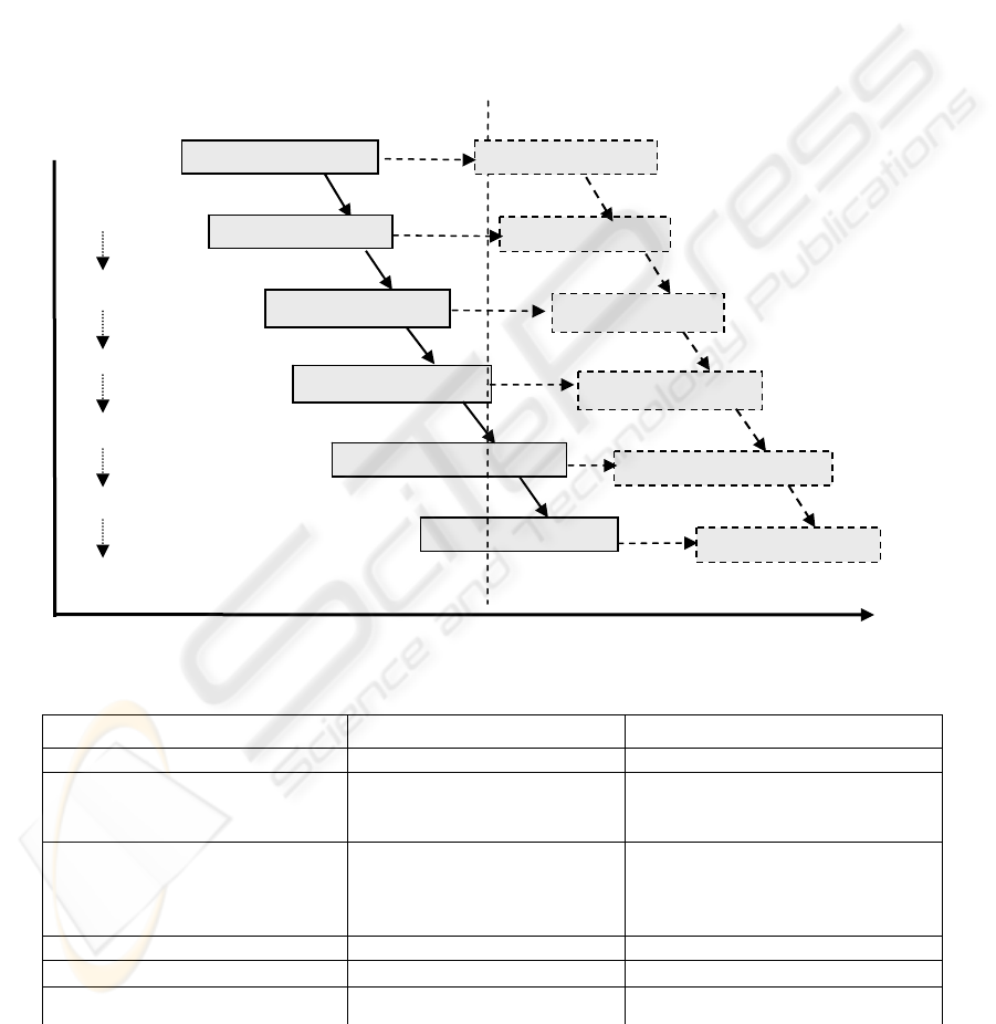
is an iterative and incremental process. As
illustrated in Figure 1, during this process, a UML
model is created and refined during consecutive
iterations and phases in the development process. In
each development phase, a system model is derived
using certain UML diagrams, depending on the
focus of the phase. Table 1 lists the UML diagrams
used to construct a model for each of the UP
development phases
.
As shown in Figure 1, the various models
derived following UP are not independent. In fact,
they are semantically overlapping and
complementary when presenting the target system as
a whole unit. Since, each model is a set of UML
diagrams (see Table 1); the UP model dependencies
implicitly imply dependencies among the UML
diagrams used.
Use case Model
Analysis
Model
Desi
g
n Model
Com
p
onent Model
Deployment
Model
test Model
Specified by
Tested b
y
I
m
p
lemented b
y
D
istributed b
y
Realized by
U
se case Model
Anal
y
sis Model
Design Model
Component Model
De
p
lo
y
men
t
Model
test Model
Specified by
Tested b
y
I
m
p
lemented b
y
D
istributed b
y
Realized by
Second iteration First iteration
a
ctivities
Requirement
Capture
Analysis
Design
Distribution
Deployment
Test
Figure 1: UP models and their relationships (Jacobson et al., 1999)
Table 1: UML diagrams used in UP models (Jacobson et al., 1999)
Activities UP Models UML Diagrams
Requirements Capture Use case model Use case diagram
Analyze
Analysis Model
Collaboration Diagram
Sequence Diagram
Activity Diagram
Design
- System
- Interface
- Data Base
Design Model
Class Diagram
Object Diagram
Package Diagram
State-Transition Diagram
Distribution Distribution Model Deployment Diagram
Implementation Implementation Model Component Diagram
Test Test Model
ICEIS 2004 - INFORMATION SYSTEMS ANALYSIS AND SPECIFICATION
186

UP highlights the implicit relationships among a
system models such as “specified by”, “realized by”,
“implemented by”, etc (see Figure 1). These implicit
relations will be the basis of our approach to a
modular verification of UML models
.
4 MODULAR VERIFICATION OF
UML MODELS
To manage the complex analysis of a UML model
and verify both the syntactic and semantic aspects of
a system model, we propose to:
1. define a model’s inter-diagram implicit
relations as proposed by UP, and
2. use the defined relations (along with the
UML syntactic dependencies) to infer that a
UML model satisfies a given property by
verifying that certain diagrams of the model
satisfy the property.
We next introduce several definitions that we
use to formalize the inter-diagram relations and to
provide for a modular verification of an UML
model.
4.1 Definitions
Similar to UP, we suppose that a UML system
model (M) is a set of UML diagrams (Jacobson et
al., 1999) that represent different aspects of the
system at a certain level of abstraction. A model
describes the static, dynamic or functional aspects of
a system. Formally, a system model M is the
structure <
D
,
R
inter
> where
D
is a set of UML
diagrams and
R
inter
is a set of relationships between
diagrams in
D
. The set of inter-diagram relations
R
I
nter
is the object of this paper. It is detailed in the
next Section.
In general, a diagram D == < E , R
intra
> where
- E: a set of structural elements (e.g. use cases,
actors, classes,).
- R
intra:
a set of relations between the structural
elements, defined according to the UML
syntax and semantics (UML Group, 1997).
For the complete set of UML structural
elements, we refer the reader to the UML semantics
(UML Group, 1997). In addition, the meta-model of
UML details out the relationships between the
structural elements of each UML diagram (UML
Group, 1997). Due to space limitations, we next
detail out only the three diagrams used in this paper
to illustrate our verification method; the remaining
UML diagrams can be defined in a similar manner.
A use case diagram is the structure
U
c
== <A
∪
U, R
intra
> where
Def
- A = { a
1
,…….,a
n
} is a set of actors,
- U = { u
1
,………,u
m
} is a set use cases each
of which is described by a sequence of
actions,
- R
intra
is a set of relations from the set {
<<extend>>, <<include>>, <<
communicate >>, <<Generalize>> } and
defined between the structural elements
A
∪
U according to the UML syntax (UML
Group, 1997).
A collaboration diagram is the structure
C
o
== <O, L
∪
M> where
Def
- O = {o
1
,……,o
u
} is a set of objects,
- L = {l
1
,…….,l
v
} is a set of links
between objects,
- M = { m
1
,…,m
w
} is a set of messages
between objects.
4.2 Inter-diagram relations in a UML
Model
Our verification method exploits the implicit inter-
diagram relations inspired from UP. These relations
are defined between the diagrams of a given UML
system model. They are presented in Figure 2 as a
directed, labeled graph. In the graph, vertices
represent UML diagrams and edges represent the
dependency relations between the diagrams.
We call the set of relations defined in the inter-
diagram dependency graph of Figure 2 the implicit
relations. These relations reflect the inter-model
relations presented in the UP design process (see
figure 1). We can therefore surcharge their definition
over the set of system models as follows:
Def
Definition 1
Let M
1
= <
D
1
,
R
1
> and M
2
= <
D
2
, ,
R
2
> be
two system models. We say, “r is an implicit
relation between M1 and M2”, if and only if there
exists D
1
∈
D
1
and D
2
∈
D
2
, such that r is an
implicit relation between D
1
and D
2
UML MODEL VERIFICATION THROUGH DIAGRAM DEPENDENCY RELATIONSHIPS
187
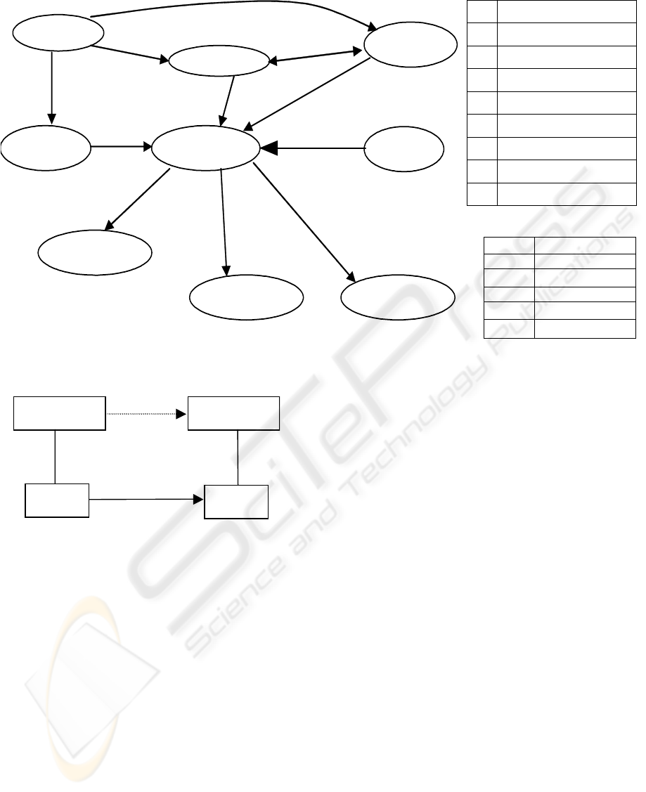
U
c
Use case diagram
C
o
Collaboration Diagram
S
q
Sequence Diagram
A
c
Activity Diagram
O
b
Object Diagram
C
l
Class Diagram
S
t
State Diagram
C
m
Component Diagram
D
p
Deployment Diagram
Spec Specified by
Equi Equivalent to
Real Realized by
Inst Instantiated by
Impl Implemented by
Dist Distributed by
U
c
A
c
C
o
C
l
S
q
C
m
S
t
O
b
D
p
<< Spec>>
<<Spec>>
<<
Spec>>
<<Impl>>
<<
Inst>>
<<
Equi
>>
<<Dist>>
<<Real>>
<<
Spec>>
<<Real>>
<<Real>>
Figure 2: Inter-diagram dependency graph
.
For example, (see Figure 3), according to the UP,
the use case model of a system is specified by its
analysis model. Thus, we can deduce that the use
case diagram (in the use case model) and the
collaboration diagram (in the analysis model) are
related by the <<spec>> relation.
Informally, a use case diagram U
c
is specified by
a collaboration diagram C
o
., denoted as U
c
<<spec>> C
o
, if and only if for each structural
element e in U
c
there is a set of structural elements
{e
k
} in C
o
, that describes the same concept
represented by e. The following examples represent
the concept correspondence between the structural
elements of U
c
and those of C
o
:
a- each actor in U
c
is represented by an object
in C
o
;
b- each action in U
c
textual description is
represented by a message in U
o
;
4.3 UML Model Verification
Use case Model
Analysis
Model
U
c
Specified
by
C
o
<<spec>>
∈
∈
The inter-diagram relations defined above can be
exploited to reduce the verification of a UML model
to the verification of some of its diagrams and not all
of them.
A UML diagram D satisfies a logic formula P (D
╞ P) is defined inductively based on the type of D
and the syntax of P. For instance, let us define the
case when D is a use case diagram.
Figure 3: Example of an Inter-model relation
Definition 2
A use case diagram U
c
== < A
∪
U, R
intra
>
satisfies the prepositional logic formula P (U
c
╞ P)
if an only if:
Def
1. there exists either:
a. an actor a ∈ A that represents P and P is a
predicate; or
b. a use case u ∈ U “representing” P and P is a
predicate.
2. if P expressed in terms of the p
1
, p
2
predicates
and
a. there exists a relation a <<communicate>> u
∈ R
intra
such that a represents p
1
and u
represents p
2
and P = p
1
∧
p
2
,
b. there exists a relation u
1
<<include>>u ∈ R
intra
such that u
1
represents p
1
and u
2
represents p
2
and P = p
1
Æ
p
2
,
c. there exists a relation u
1
<<extend>>u
2
∈ R
intra
such that u
1
represents p
2
and u
2
represents p
2
and P = p
2
Æ
p
1
.
ICEIS 2004 - INFORMATION SYSTEMS ANALYSIS AND SPECIFICATION
188

3. if P =
¬
P’, then U
c
does not satisfy P’.
4. if P1, P2 are two formulas, and
a. P= P1 ∨ P2 then either U
c
╞ P1 or U
c
╞ P2.
b. P= P1 ∧ P2 then U
c
╞ P1 and U
c
╞ P2.
Definition 3
A UML model M satisfies a property P (M ╞ P)
if and only if each diagram D in M satisfies P (D
╞
P).
To illustrate our modular verification approach,
the following proposition states how the
specification relation <<spec>> can be used to
reduce the verification of a UML model to the
verification of some of its diagrams.
Proposition
Let D
1
and D
2
be two UML diagrams and P be a
prepositional logic formula. If D
1
╞ P and
D
1
<<spec>>D
2
, then D
2
╞ P.
Using this proposition, if U
c
╞ P then for each
diagram D reachable from U
c
through edges labeled
with <<spec>>, we have D ╞ P. Thus, we only
need to verify the remaining diagrams of the model.
4.4 Example
In this section, we illustrate our UML model
verification approach using the Automatic Teller
Machine (ATM) example. Figure 4 shows a part of
the ATM model which is expressed through a use
case diagram U
c
, an activity diagram A
c
and
collaboration diagram C
o
. The ATM use case
diagram, shown in Figure 4-a, specifies the
functional aspect of the ATM system. A part of the
ATM dynamic system aspect is described by an
activity (Figure 4-b) and a collaboration diagram
that describes the interactions among the system
objects (Figure 4-c).
Suppose we want to verify the following ATM
property P: “every customer can withdraw money if
he/she can be identified by the bank host”. To
express formally P, we use the following
predicates and propositions:
- customer(c) : c is a customer.
- identification(c): c is identified as a client.
- withdraw_money(c): c withdraws money.
Thus, the property P can be expressed formally
by the following proposition:
withdraw_money(c) → (customer(c) ∧
identification(c)).
To prove that the ATM model satisfies the
property P, we follow the next two steps:
1. verify that U
c
╞ P,
2. verify that U
c
<spec>> C
o
Verifying that U
c
╞ P can be easily through a
syntactic analysis of the diagram and a
correspondence among the use case diagram
structural elements and formula components. Let us
establish the following trivial correspondence
between the predicates of P and the use case diagram
elements:
• the actor “costumer” represents the predicate
customer(c),
• the use case “withdraw_money” represents the
predicate withdraw_money(c),
• the use case “identification” represents the
predicate identification(c).
In this example, we have:
P = withdraw_money(c) → (customer(c) ∧
identification(c)),
Thus, P = (withdraw_money(c) → customer(c))
∧ (withdraw_money(c) → identification(c)).
Hence, according to definition 1, we have:
1. U
c
╞ (withdraw_money(c)
→
identification(c)) since the relation
“costumer <<communicate >>
withdraw_money” is in U
c
, and
2. U
c
╞ (withdraw_money(c)
→
identification(c)) since the relation
“withdraw_money <<include>>
identification” is in U
c
.
Using this syntactic inspection of the ATM use
case diagram, we easily conclude that U
c
╞ P.
In the second step, we verify that U
c
<<spec>>
C
o
and U
c
<<spec>> A
c
. The verification of the
<<spec>> relation between U
c
and C
o
is based on a
list of UML syntactic and semantic rules that relate
the two diagrams. It used detailed inspections of the
structural elements of the use case diagram (e.g., the
pre- and post-conditions and the guards of the
activity diagram).
In this step, it must be confirmed that the
collaboration diagram and activity diagram are able
to cope with the use case diagram.
Finally, we have U
c
╞ P and
U
c
<<spec>> C
o
,
and
U
c
<<spec>> A
c
Thus by this proposition
C
o
╞ P, and A
c
╞P
UML MODEL VERIFICATION THROUGH DIAGRAM DEPENDENCY RELATIONSHIPS
189
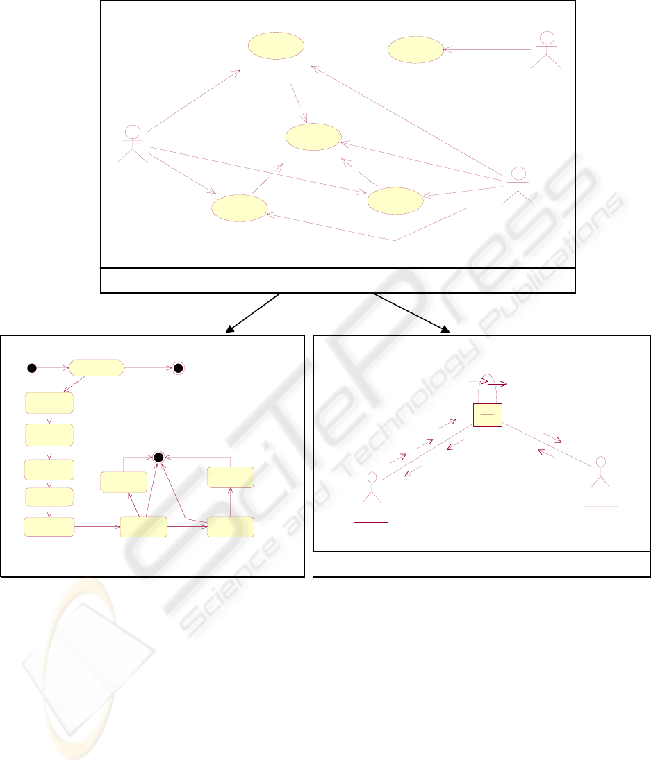
Customer
Transfer Funds
Identification
<<include>>
Withdraw Money
<<include>>
Deposit Money
<<include>>
Bank Host
Supply Money
operator
(
a
)
the ATM use case dia
g
ra
m
<<spec>> <<spec>>
According to Definition 3, we therefore
conclude that the ATM model (with its presented
diagrams) satisfies the property P (ATM model ╞
P).
5 CONCLUSION AND FUTURE
WORKS
During the Unified Process, a variety of UML-based
models of a system are developed. These models are
implicitly related to one another and are
semantically overlapping and complementary. The
implicit relations among a UML model’s diagrams
derived through UP (together with the UML
syntactic dependency relations) can be exploited in a
modular verification of a UML model. In this paper,
we showed the feasibility of this verification
approach using a simple example that contains only
tree diagrams and one implicit relationship
<<spec>>.
We are currently completing the formalization of
the implicit inter-diagram relations and examining
the set of properties verifiable through this approach.
id enti ficati on
Get
Selection
Get Am ou n t
Check
Amount
Write
Ca rd
Eject Card
Take Card
Retract
Card
Dispense
Money
Take Money
(b) Activity Diagram
: Customer
AT M
: Bank Host
1: Card i ntroducti on
2: Card Verification
3: Get PIN code
4: Code PIN(value)
5: Code verification
6: Get Autorisation
7: Autorization(Sold)
8: Get Amount
9: Amount(value)
(c) Collaboration Diagram
Figure 4: The realization of use case
ICEIS 2004 - INFORMATION SYSTEMS ANALYSIS AND SPECIFICATION
190

REFERENCES
Anthony, J. H., 1990. Using Z as a specification calculus
for object-oriented systems. In D. Bjorrner, C.A.R.
Hoare, and H. Langmaack, editors, VDM and Z,
Formal Methods in Software Development, volume
428 of LNCS, pages 290—318. VDM-Europe,
Springer-Verlag, New York.
Broy, M., 2003. Unifying Models and Engineering
Theories of Composed Software Systems. UNU/IIST –
IFIP WG 2.3 Summer School.
Cook, S., Daniels, J., 1994. Let’s get Formal. Journal of
Object-Oriented Programming (JOOP), pages 22-24
and 64-66.
D’Souza, D.F., Wills, A.C., 1999. Objects, Components
and Frameworks with UML. The Catalysis
TM
Approach, Addision-Westly.
Duke, R., king, P., Gordon A. R., and Smith G., 1991. The
Object-Z specification language. In Timothy D.
Korson, VijayK. Vaishnavi, and Bertrand Mayer,
editors, Technology of Object-Oriented Language and
Systems; TOOLS 5, pages 465—483. Prentice Hall.
Dürr, E.H., Duursma, A., and Plat, N., 1993. VDM++
Language Reference Manual Technical Report, CAP
Gemini Innovation.
Evans, A.S., France R.B., Lano, K.C., B.Rumpe. 1999.
Meta-modeling semantics of UML, In: Behavioral
Specifications for Businesses and Systems, Kluwer,
Editor: Haim Kilov, Chapter 4.
Fernandez, J.-C., Garavel, H., Mounier, L., Rodriguez, C.,
Sifakis, J.,1992. A toolbox for the verification of
programs. In international Conference on Software
Engineering, ICSE/14, Melbourne, Australia, pages
246-259.
France, R., Bruel J. M., and Larrondo-Petrie M. 1997. An
integrated Object-Oriented and Formal Modeling
Environment. Journal of Object-Oriented
Programming(JOOP). Volume 10, Number 7, 25-30.
France, R., Evans, A., Lano K., Rumpe, B., 1998. The
UML as a formal modeling notation. Submitted to
Computer Standards and Interfaces.
Holzmann, G.J., 1997. The model checker SPIN. IEEE
transactions on software Engineering. 23(5): 279-295.
ISO. LOTOS. 1985. A Formal Description Technique
based on the Temporal Ordering of Observational
Behavior. ISO/DP 8807.
Jacobson I., Booch, G. and Rumbaug, J., 1999. The
Unified Software Development Process, Addition
Westly.
Kurchten, P., 1999. The rational Unified Process. An
Introduction. Addition Wesley Longman Inc.
Kwon, G., 2000. Rewrite rules and operational Semantics
for model checking UML statecharts. In Andy Evans,
Struart Kent, and Branselic, editors, UML 2000- the
Unified Modelling Language, Advancing the
Standard. Third International Conference, York, UK,
October 2000, Proceedings, Volume 1939 of LNCS,
page 528-540. Springer.
Lano, K.C., 1991. Z++, an object-Oriented extension to Z.
In John E. Nicholls, editor Z user Workshop, Oxford
1990, Workshops in computing, pages 151—172.
Springer-Verlag.
Latella D., Majzik I., Massink M. 1999. Automatic
verification of behavioral subset of UML statechart
diagrams using the spin model-checker. Formal
Aspects of Computing, 11:637-664.
Lucas, P., 1987. VDM: Origins, Hopes, and Achievements
VDM'87: VDM -- A Formal Method at Work, Lecture
Notes in Computer Science, Vol. 252, pp. 1-18,
Springer-Verlag.
McMillan, K. L., 1992. The SMV system, symbolic model
checking - an approach. Technical report CMU-CS-
92-131, Carnegie Mellon University.
Michael, J. S., 1992. The Z Notation: A Reference
Manual. Prentice Hall, Englewood Cliffs, NJ, Second
edition.
Paludetto, M., Détatour, J., 1999. UML et les réseaux de
Petri : vers une sémantique des modèles dynamiques
et une méthodologies de développement des systèmes
temps réel. L’Object, 5 : 443-467.
Paulo, J.F., Miguel, E.F., 2000. Carreriera and Miguel E.F
Costa. Automatically verifying an Object-Oriented
Specification of the steam-boiler System. In Stefania
Gnesi, Ina Schieferdecker, and Axel Rennoch, editors,
Proceedings of tne 5th International ERCIM
Workshop on formal Methods for Industrial Critical
Systems (FMICS’2000) page 345-360 GMD.
Pons, C., Baum G., Giandini R., 2002. Dimensions in the
object Oriented Software Development Process,
Information Resources Management Association
IRMA International Conference, Idea Group
Publishing. ISBN 1-930708-39-4, Seattle,USA.
Printz, J., 1997. Génie Logiciel, Technique de l’ingénieur,
traité informatique, H3 208-32 p.
Roebert H. B., Cheng H. C., 1995. A Formal semantics for
object model diagrams. IEEE Transactions on
Software Engineering, 21(10): 799—821.
UML Group, 1997. Unified Modeling Language, Version
1.1, Rational software Corporation, Santa Clara, CA-
95051, USA.
Utwente, 2002. Web site of University of Twente. (Page
consulted 8
th
06-2002) [on line] http://fmt.cs.
utwente.nl/courses/. Chapter 1- System Verification.
UML MODEL VERIFICATION THROUGH DIAGRAM DEPENDENCY RELATIONSHIPS
191
