
KEYS GRAPH - BASED RELATIONAL TO XML
TRANSLATION ALGORITHM
Wilmondes Manzi de Arantes Júnior
(1, 2)
, Christine Verdier
(1)
(1)
Lyon Research Center for Images and Intelligent Information Systems (LIRIS), INSA Lyon,
20 avenue Albert Einstein, Villeurbanne, France
(2)
Calystène Informatique Santé, 32 avenue du Vercors, Meylan, France
Keywords: Relational to XML translation, Keys graph, Functional dependencies
Abstract: The authors propose two algorithms for generating a DTD and an XML document respectively from the
metadata and the content of a relational database without any intermediary language or user intervention.
Such algorithms always generate semantically correct XML output by respecting database functional
dependencies represented in a graph structure they take as input. Finally, different XML representations (or
views) meeting expectations of different kind of users can be obtained from the same data according to the
data entity chosen as translation pivot.
1 INTRODUCTION
In the last years, much have been said about XML
and its applications. However, the majority of the
business data are stored in relational databases and
needs to be translated. In this paper, we present two
separated algorithms for translating the structure and
the content of a relational database respectively in a
DTD and an XML document. The algorithms use a
keys graph (
Flory & Kouloumdjian, 1978) (automatic
generation in (Manzi, Verdier & Flory, 2002)) to
represent all functional dependencies in the database
for ensuring that translation results reflect accurately
semantic relationships between data entities. The
algorithms can also generate XML output reflecting
data from the point of view of a particular data entity
(from a database containing professors and courses,
we can create, for example, a professor-centered and
a course-centered document for different purposes).
Finally, no intermediary mapping languages nor user
intervention are required.
2 EXAMPLE DATABASE
The example database we will use throughout this
paper is the following:
course-
name
course
course-id
0..N
course table
course-id course-name
C1 French
C2 sport
student table
student-id student-name
S1 Mary
S2 Marc
prof table
prof-id prof-name univ-id
P1 John U1
P2 Paul U2
P3 Carl U1
P4 Phil U2
univ table
univ-id univ-name
U1 INSA
U2 Lyon1
scores table
prof-id course-id student-id score result
P1 C1 S1 B ok
P1 C1 S2 A ok
P1 C2 S1 B ok
P2 C1 S2 C ok
result
1..1
univ prof
student
univ-name
prof-id
prof-name
student-id
student-
name
1..N
0..N
1..N
1..N
univ-id
1..N
1..N
score
Figure 1: example database.
142
Manzi de Arantes Júnior W. and Verdier C. (2004).
KEYS GRAPH - BASED RELATIONAL TO XML TRANSLATION ALGORITHM.
In Proceedings of the Sixth International Conference on Enterprise Information Systems, pages 142-148
DOI: 10.5220/0002645801420148
Copyright
c
SciTePress
2.1 Table/entity-centered translations
Some algorithms transforms relational data in such a
way that all tags and attributes in the resulting XML
document represent database tables, rows, columns,
data types, field lengths, default values and so on.
We call this kind of transformation table-centered.
In this paper, we follow an entity-centered approach
in which the XML document we generate contains
only high-level concepts present in the database
Entity-Relationship model: data entities, associations
(represented by element nestings) and attributes.
3 DTD GENERATION
This algorithm is executed according to a data entity
called pivot node which determines the meaning of
the resulting XML representation since all database
content is rearranged in order to present data from its
point of view. The steps of the algorithm are:
3.1 Choosing the pivot node
As the translation always begins with a data entity,
the pivot node must be intermediary. Suppose we
have chosen prof-id:
3.2 Traversing the sub-graph below it
In this phase, the algorithm visits the sub-graph 1.
The first node to be analyzed is the pivot node itself,
which is an
intermediary one. Then we:
(A) create a composite DTD element having the
same name as the node table (prof) and whose
children list is initially empty;
(B) create a new PCDATA element having the same
name as the node attribute (prof-id);
(C) add the name of the DTD element created in B
to the children list of the element created in A.
(A) (B)
<!ELEMENT prof ( )> <!ELEMENT prof-id (#PCD)>
<!ELEMENT prof (prof-id)>
(C)
Next step consists in traversing all non-visited edges
starting at the pivot node. Next node is prof-name,
which is a
leaf one. Then we:
(D) create a new PCDATA element having the same
name as the attribute of the node (prof-name).
Now, we will represent in the DTD the edge linking
prof-id and prof-name by creating a nesting between
the DTD elements generated by these nodes. So, we:
(E) add the name of the DTD element created by the
destination node in D to the children list of the
DTD element created by the origin node in A/C:
<database>
<table1>
<row>
<att1>V1</att1>
<att2>V2</att2>
</row>
…
</table1>
…
</database>
<database
<entity1>
<att1>V1</att1>
<entity2>
<att2>V2</att2>
<att3>V3</att3>
</entity2>
</entity1>
…
</database>
Figure 2: table and entity-centered translations.
(D)
<!ELEMENT prof-name (#PC)>
(E)
<!ELEMENT prof (prof-id, prof-name)>
Next two nodes we visit are univ-id and univ-name,
which are treated according to the rules used in A, B
and C. So we have three new elements:
<!ELEMENT univ (univ-id, univ-name)>
<!ELEMENT univ-id (#PCDATA)>
<!ELEMENT univ-name
(
#PCDATA>
Finally, we indicate there is an edge between prof-id
and univ-id by creating a nesting between the DTD
elements they created:
scores
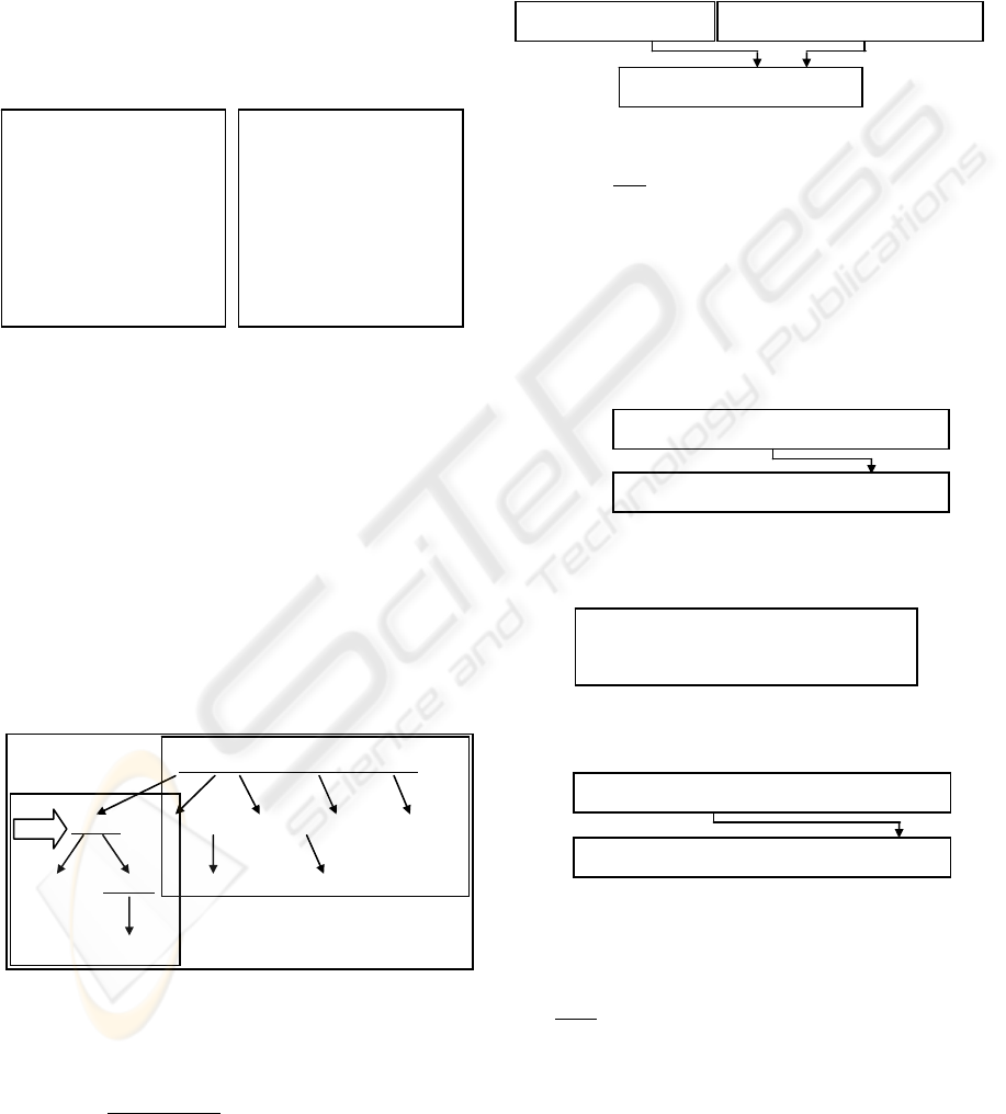
3.3 Traversing the sub-graph above it
Now, we will traverse the sub-graph 2. Next node is
the head of the graph which, differently from leaf
and intermediary ones, does not create any DTD
element. As the order in which branches starting at a
head node are visited determines the meaning of the
translation result, they are sorted so that branches
starting with key attributes (e.g. course-id) appear
<!ELEMENT prof (prof-id, prof-name, univ)>
<!ELEMENT univ (univ-id, univ-name)>
scores
cou
r
se
-i
d
s
t
ude
nt-i
d
course-name
course student
course
prof-id + course-id + student-id
prof
prof-id
sco
r
e
scores
prof-name univ-id
univ-name
student-name
univ prof
univ
student
result
pivot
sub-
graph 2
sub-
graph 1
KEYS GRAPH - BASED RELATIONAL TO XML TRANSLATION ALGORITHM
143

before branches starting with relationship attributes
(e.g. score).
Once graph branches are ordered, the algorithm
traverses each non-visited one. Each time it finishes
visiting a branch b, we indicate that b is linked to the
graph head by creating a nesting between the DTD
elements generated by the first node of b and by the
first node of the branch visited immediately before
b. For example, the first node of the branch starting
with course-id create the following DTD element:
Then, for indicating the link between this branch and
the graph head, we add the name of this element to
the children list of the element created by the first
node of the last visited branch (starting at prof-id):
The next branch we visit starts with student-id node
and its relationship with the last visited one (starting
with course-id) is indicated as follows:
Finally, we reach the nodes representing relationship
attributes, and all remaining nestings will be made
between the PCDATA elements they create and the
composite element created by the first node of the
last branch starting with a key attribute (student-id):
In the next section we present an algorithm for
predicting the cardinalities of all nestings we have
created so far.
3.4 Determination of cardinalities
Each time we create a nesting between two elements
E1 and E2, we predict the cardinality ω of E2 with
relation to E1 (<!ELEMENT E1(E2ω)>) as follows:
(A) If we are analysing a key attribute contained in
an intermediary node, the cardinality is 1..1 for
sure.
for example, the cardinality of the key
attribute att in the children list of tab
element is 1..1 for sure.
<!ELEMENT tab (att, …)>
(B) If we are going down between two graph nodes,
the cardinality is 1..1 for sure because upper
attributes functionally determines lower ones.
for example, att2 and att3 have
cardinalities 1..1 for sure in the
children list of tab element.
<!ELEMENT tab (att1, att2, att3, …)>
att1
tab
(C) If we are going up or at the same level in the
graph, the destination node attribute is not
functionally determined by the origin node one.
Then, we query the database and the cardinality
is predicted by composing the two rules below:
Rule 1: IF at least one instance of the origin
node attribute is linked to no instances of the
destination node attribute THEN the minimum
cardinality is 0 for sure, ELSE it can be 1;
Rule 2: IF at least one instance of the origin
node attribute is linked to several instances of
the destination node attribute, THEN the
maximum cardinality is N for sure, ELSE it
can be 1. The composition table is:
Rule 1 Rule 2 Result Likelihood
apply apply 0..N (*) sure
apply not apply 0..1 (?) not sure
not apply apply 1..N (+) not sure
not apply not apply 1..1 ( ) not sure
For example, when going from prof-id to course-id
nodes, we predict the cardinality of course element
in the children list of prof element by applying these
rules to the scores table. Rule 1 applies as at least
one value of the origin node is linked to no value of
the destination node (P3 has no entries in the table).
Rule 2 applies as at least one value of the origin
node is linked to several values of the destination
node (P1 is linked to C1 and C2). So, the first line of
the composition table states that the cardinality of
course element is 0..N (“*” symbol) for sure.
The final DTD the algorithm generates is (PCDATA
elements are note included for space reasons):
The complete algorithm for generating a DTD
from a relational database is presented in figure 3.
<!ELEMENT course (course-id, course-name)>
<!ELEMENT prof (prof-id, prof-name, univ, course)>
<!ELEMENT course (course-id, course-name)>
<!ELEMENT course (course-id, course-name, student)>
<!ELEMENT student (student-id, student-name)>
att
tab
prof-id course-id
prof
prof-id + course-id + …
course
scores
<!ELEMENT prof (prof-id,
prof-name, univ, course*)>
att2
tab
att3
tab
<!ELEMENT score (#PC)> <!ELEMENT result (#PC)>
<!ELEMENT student (student-id, …, score, result)>
<!ELEMENT prof (prof-id, prof-name, univ, course*)>
<!ELEMENT univ (univ-id, univ-name)>
<!ELEMENT course (course-id, course-name, student+)>
<!ELEMENT student (student-id, student-name, score,
result
)
>
ICEIS 2004 - DATABASES AND INFORMATION SYSTEMS INTEGRATION
144

4 XML DOCUMENT
GENERATION
Our second algorithm generates an XML document
from a relational database. In this document, tags
reflect database structure (as described by its DTD)
and contents are retrieved from database tables. The
algorithm starts at a pivot node and visits all nodes
below and above it generating XML tags and SQL
queries. In our example, suppose we chose prof-id
attribute as pivot, which is
intermediary. Then we:
(A) create an empty XML tag (element) having the
same name as the node table (prof):
because it is the pivot node, we create an SQL
query for retrieving all values of its attribute
(prof-id) from its table (prof). The query and the
result are:
(B) visit, for each retrieved value, all subsequent
graph nodes. The first value is P1. Then, we
create an XML tag having the same name as the
node attribute (prof-id) and whose value is P1,
and we add this new tag into the tag created in A
(which is initially empty):
NBV = graph node being visited, PVN = prior visited graph node, ELEM = actual DTD element
function buildDTD ( GraphNode NBV , GraphNode PVN , DTDElement ELEM ) returns DTDElement
if ( NBV is leaf ) then
E1 Å new PCDATAElement ( NBV.attribute() )
ELEM.addArgument ( E1 , “ 1..1” )
return ELEM
else if ( NBV is head ) then
sort NBV children so that branch with pivot node is at left and branches starting with relationship attributes at right
EX Å ELEM
for each N1 Å non-visited NBV child from left to right do
E2 Å buildDTD ( N1 , PVN , EX )
if ( N1 is not a leaf ) then
PVN Å N1
EX Å E2
return ELEM
else
E3 Å new CompositeElement ( NBV.table() )
E4 Å new PCDATAElement ( NBV.attribute() )
E3.addArgument ( E4 , 1..1 )
if ( ELEM is not null ) then
C Å calculateCardinality ( PVN , NBV )
ELEM.addArgument ( E3 , C )
for each CN Å non-visited NBV child from left to right do
buildDTD ( CN , NBV , E3 )
FN Å non-visited father node of NBV below the graph head whose branches contain the pivot node
if ( FN exists )
then buildDTD ( FN , NBV , E3 )
return E3
function call : GraphNode PN = pivot node of translation
CompositeElement rootElement = buildDTD ( PN , null , null )
(C) visit the sub-graph below the pivot node for the
value P1. Next node, prof-name, is a
leaf. Then,
we create an SQL query for retrieving the value
of this attribute as functionally determined by
the actual value of the father node attribute
(prof-id = P1). The query and the result are:
now, we create an XML tag with the same name
as the node attribute (prof-name), whose value
is John, and we add it into the tag created in A/B
Next node, univ-id, is intermediary, so the process is
the same as for prof-id. Then, we represent the edge
linking univ-id to prof-id through a nesting between
the XML tags representing them.
Now, the translation algorithm goes up in the
graph and reaches its
head. Again, it traverses all
<prof></prof>
<prof-id> P1 </prof-id>
<prof>
<prof-id> P1 </prof-id>
</prof>
SELECT prof-id FROM prof P1, P2, P3, P4
Figure 3: algorithm for generating a DTD from a relational database.
XML tag
created by
prof-name
node
<prof>
<prof-id> P1 </prof-id>
<prof-name> John </prof-name>
</prof>
John
SELECT prof-name FROM prof
WHERE prof-id = P1
KEYS GRAPH - BASED RELATIONAL TO XML TRANSLATION ALGORITHM
145

non-visited graph branches from left to right creating
nestings linking the actual branch either to the last-
visited or to the last one starting with a key attribute.
All branches must be ordered as stated before.
Next branch starts with course-id node. Then,
we retrieve all values of its attribute as functionally
determined by the combination of the values of the
previous visited nodes starting with key attributes
(prof-id = P1). In other words, we want to know all
courses taught by professor P1:
Once again, the algorithm must visit all subsequent
graph nodes for each retrieved value. For course-id
= C1, an XML tag is created and added into the tag
representing the last visited graph branch, prof-id:
For the next branches, we must combine the values
of all already visited key attributes (prof-id = P1 and
course-id = C1). Next one starts with student-id:
XML
tag
created
by
course-
id node
<prof>
…
<course>
<course-id> C1 </course-id>
<course-name>French</course-name>
</course>
</
p
rof>
SELECT course-id FROM score
WHERE prof-id = P1 GROUP BY course-id
C1
C2
SELECT student-id FROM score
WHERE (prof-id = P1) AND (course-id = C1)
GROUP BY student-id
S1
S2
NBV = graph node being visited , ELEM = actual XML element , TableName = name of a database table ,
CLAUSES = list of and clauses (like a=b) , IND = index of the child node the algorithm will visit
function buildXML (GraphNode NBV, XMLElement ELEM, ANDClauses CLAUSES, Str tableName, int IND) returns
XMLElement
if ( NBV is leaf ) then
DATASET1 Å select NBV.attribute() from tableName where CLAUSES group by NBV.attribute()
LINE1 Å single line in DATASET1
E1 Å new XMLElement ( NBV.attribute() , LINE1.value() )
ELEM.addChild ( E1 )
return ELEM
else if ( NODE is head ) then
sort NBV children so that branch with pivot node is at left and branches starting with relationship attributes at right
DATASET2Å select NBV.child(IND).attribute() from tableName where CLAUSES group by NBV.child(IND).attribute()
IND2 Å IND + 1
for each LINE2 Å line in DATASET2 do
CLAUSES2 Å [ NBV.child(IND).attribute() = LINE2.value() ]
E2 Å buildXML ( NBV.child(IND) , ELEM , CLAUSES2 , NBV.child(IND).table() , 0 )
CLAUSES.addOrUpdateClause ( NBV.child(IND).attribute() = LINE2.value() )
if ( IND2 ≤ number of children of NBV )
then buildXML ( NBV , E2 , CLAUSES , NBV.table() , IND2 )
return ELEM
else
if ( CLAUSES is not null )
then DATASET3 Å select NBV.attribute() from tableName where CLAUSES
else DATASET3 Å select NBV.attribute() from NBV.table()
for each LINE3 Å line in DATASET3 do
E3 Å new XMLElement ( NBV.table() , “” )
E4 Å new XMLElement ( NBV.attribute() , LINE3.value() )
E3.addChild ( E4 )
ELEM.addChild ( E3 )
CLAUSES3 Å [ NBV.attribute() = LINE3. value() ]
for each CN Å non visited NBV child from left to right do
if ( CN is intermediary )
then buildXML ( CN , E3 , CLAUSES3 , NBV.table() , 0 )
else buildXML ( CN , E3 , CLAUSES3 , CN.table() , 0 )
FN Å non-visited father node of NBV below the graph head whose branches contain the pivot node
if ( FN exists )
then buildXML ( FN , E3 , CLAUSES3 , FN.table() , 2 )
return E3
function call : GraphNode PN = pivot node of translation
XMLElement rootElement = new XMLElement ( “database” , “” )
buildXML ( PN , rootElement , [ ] , “” , 0 )
Then, for each retrieved value, we must traverse the
branch starting with student-id and add the created
tag into the tag created by course-id branch.
The last branches contain relationship attributes
and must be linked to the last visited branch starting
with a key attribute (student-id). Again, their values
are functionally determined by the combination of
Figure 4: algorithm for generating an XML from a relational database.
ICEIS 2004 - DATABASES AND INFORMATION SYSTEMS INTEGRATION
146

the values of the previous visited key nodes, prof-id
= P1, course-id = C1 and student-id = S1:
As score and result are leafs, their tags are added to
the tag created by student-id node:
Although the graph traversal is finished at this point,
the created XML document contains only data about
professor P1, course C1 and student S1. Then, for
translating available data about the other elements,
we must revisit previous visited branches starting
with key attributes from right to left in order to take
into account all possible combinations of values of
these three attributes in the database. According to
the scores table, such combinations are:
Now we come back to the last visited branch starting
with a key attribute, student-id, whose next value is
S2 and we re-traverse all subsequent graph nodes. At
this point, all values of student-id will be analyzed,
then we come back to the prior branch, course-id. Its
next value is C2. Again, all remaining branches are
visited. The translation is complete when the graph
is traversed for all of the combinations above.
The complete algorithm for generating an XML
document from a relational database is presented in
figure 4.
5 RELATED WORK
The translation of relational data into XML has been
addressed by many researchers. Table-centered-only
approaches are rare (Turau, 1999). On the other
hand, entity-centered approaches are numerous. In
XPERANTO (Carey et al. 2000) and SilkRoute
(Fernandez, Suciu & Tan, 2000; Fernandez et al.
2001) users can specify entity-centered XML views
over a relational database respectively through the
mapping languages XQuery and RXL (proprietary).
XML/SQL (Vittori, Dorneles & Heuser, 2001) is
another proprietary language which allows users to
define the structure of the final XML document, but
they must also specify SQL queries for retrieving the
data. In (Shanmugasundaram et al., 2000), SQL
language is extended with XML translation and
aggregation functions, but nestings in the final XML
document are defined by users through complicated
nested SQL queries. In (Lewis, 2002), users create a
DTD or an XML-Schema which describes the XML
document they need and the necessary SQL queries
are generated by the system, but users must avoid
demanding data from tables that can not be joined.
An hybrid table/entity-centered redundancy free
approach is proposed in (Liu C., Liu J. & Guo,
2003), where a relational schema is translated into
an XML-schema. NeT (Lee et al., 2001) and CoT
(Lee et al., 2002) algorithms take database create
statements as input. Then, the first creates a DTD by
using an operator which deduces cardinalities, but it
is only applicable to a single table at a time. The
second handles several tables but outputs data in a
proprietary language called XSchema. In (Kleiner &
Lipeck, 2001), the authors also propose an algorithm
for creating a DTD from an ER-Schema. However,
while their DTD starts only with entities that are not
functionally dependent on other ones, our DTD can
start with any data entity. Mapping rules are also
different: while we map data entities, attributes and
relationships into DTD elements and nestings, they
map them respectively into DTD elements, attributes
and nestings or elements.
B
SELECT score FROM scores WHERE (prof-id =
P1) AND (course-id = C1) AND (student-id = S1)
ok
SELECT result FROM scores WHERE (prof-id =
P1) AND (course-id = C1) AND (student-id = S1)
<prof>
…
<student>
…
<score> B </score>
<result> ok </result>
</student>
</
p
rof>
XML tags
created by score
and result nodes
prof-id = P1, course-id = C1, student-id = S1
prof-id = P1, course-id = C1, student-id = S2
prof-id = P1, course-id = C2, student-id = S1
prof-id = P2, course-id = C1, student-id = S3
6 CONCLUSION
We have presented two algorithms for translating the
structure and the content of a relational database
respectively into a DTD and an XML document.
They ensure the semantic correctness of the result by
respecting database functional dependencies thanks
to a directed graph indicating them. Additionally,
these algorithms can create different entity-centered
views of the same data. Finally, they require no user
intervention, nor intermediary languages specifying
mapping schemes. In the future, some improvements
can be made in order to reduce the redundancy in the
final XML document and the great number of SQL
queries executed against the database.
REFERENCES
Carey M., Florescu D., Ives Z. et. al., ‘XPERANTO:
Publishing Object-Relational Data as XML’,
Workshop on the Web and Databases, 2000.
KEYS GRAPH - BASED RELATIONAL TO XML TRANSLATION ALGORITHM
147

Fernandez M., Morishima F., Suciu D. et. al., ‘Publishing
Relational Data in XML: the SilkRoute Approach’,
Data Engineering, 24:2 (2001), 12-19.
Fernandez M., Suciu D., Tan W., ‘SilkRoute: trading
between relations and XML’, In Proceedings of the
WWW9, pages 723-746, Amsterdam, 2000.
Flory A., Kouloumdjian J. 1978, ‘A model and a method
for logical database design’. In 4th int. conf. on VLDB,
Berlin, 333-350.
Kleiner C., Lipeck U. W., ‘Automatic Generation of XML
DTDs from Conceptual Database Schemas’, GI
Jahrestagung (1) 2001: 396-405.
Lee D., Mani M., Chiu F. et al., ‘Nesting-based
Relational-to-XML Schema Translation’, In
International Workshop on the Web and Databases,
Santa Barbara, CA, May 2001.
Lee D., Mani M., Chiu F. et. al., ‘NeT & CoT: Translating
Relational Schemas to XML Schemas using Semantic
Constraints’, In: 11th ACM CIKM Conference,
McLean, USA, 2002.
Lewis B., ‘Extraction of XML from Relational Databases’,
EDBT Workshops 2002: 228-241.
Liu C., Liu J., Guo M., ‘On Transformation to
Redundancy Free XML Schema from Relational
Database Schema’, APWeb 2003: 35-46.
Manzi W., Verdier C., Flory A., ‘XML-Based Document
to Query a Relational Database’, ICEIS 2002: 26-33.
Shanmugasundaram J., Shekita E., Barr R. et. al.,
‘Efficiently Publishing Relational Data as XML
Documents’, VLDB Conference, 2000.
Turau V., ‘Making Legacy Data Accessible For XML
Applications’, 1999.
Vittori C. M., Dorneles C.F., Heuser C.A., ‘Creating XML
Documents from Relational Data Sources’, EC-Web
2001: 60-70.
ICEIS 2004 - DATABASES AND INFORMATION SYSTEMS INTEGRATION
148
