
FROM UML TOWARDS PETRI NETS
TO SPECIFY AND VERIFY
Thouraya Bouabana-Tebibel
Institut National d’Informatique BP 68M, Oued-Smar 16270, Algiers, Algeria
Mounira Belmesk
Collège Edouard MonPetit, Longueuil, Canada
Keywords: UML, Petri nets, verification and validation, class diagram, statechart diagram, collaboration diagram
Abstract: UML nowadays, has emerged as the industr
y standard for object-oriented modeling. However, it still lacks a
well-defined semantic base enabling it to perform formal verification and validation tasks. Our goal being to
provide system designers a life cycle of software development integrating conviviality and rigor, we
propose a methodology to specify, verify and validate using UML. This methodology is based on a
technique which derives colored Petri nets from UML class, statechart and collaboration diagrams. The
approach that we propose associates the formalization of the object dynamics to the formalization of the
object behavior. A case study is provided to illustrate this technique.
1 INTRODUCTION
UML (OMG, 2001) is currently considered as the
universal notation for object-oriented specification
of complex system artifacts, in graphic and
documented form. Nevertheless, it lacks a well-
defined semantic which allows the use of formal
proof techniques guaranteeing the precision and the
correctness of the modeling.
The class diagram models the static structure of
a syste
m, in terms of classes and relationships
between these classes, where the objects represent
the class instances and the associations represent the
relation instances. The statechart diagram describes
in a formal manner the behavior of the objects of a
given class by way of states and events. The
collaboration diagram shows the object interactions
by emphasizing in particular, the static structure
which allows the object group collaboration.
On the other hand, Petri nets (Jensen, 1992) are a
fo
rmal and graphical appealing language that relies
on a mathematical theory which permits abstract
proof activities. Colored Petri nets are a
generalization of ordinary Petri nets, allowing
convenient definition and manipulation of object
values. Because of its rigor and reliability, the use of
formal specification is increasingly present in the
world of modeling, in spite of its complex approach.
We are interested in this paper, in developing a
meth
odology which will associate, the object-
oriented modeling to the formal specification in
order to compensate between the limits of one
versus the constraints of the other. This
methodology starts from a UML modeling to derive
colored Petri nets from class, statechart and
collaboration diagrams. The statechart diagram
generates a Petri net translating the operational and
dynamic behavior of the object. The collaboration
diagram afterwards intervenes in the interconnection
of the different object Petri nets, thus assuring their
interaction. As far as the class diagram is concerned,
its role is to precise the object roles and to provide
the OCL invariants.
The remainder of the paper starts with a brief
expose on the
current trends on this research and
works similar to the work presented herein. Then,
we present the proposed methodology and the
development of the technique upon which it is
based. This technique is illustrated in a case study.
We conclude with observations on the obtained
results and recommendations of future research
direction.
249
Bouabana-Tebibel T. and Belmesk M. (2004).
FROM UML TOWARDS PETRI NETS TO SPECIFY AND VERIFY.
In Proceedings of the First International Conference on Informatics in Control, Automation and Robotics, pages 249-256
DOI: 10.5220/0001145802490256
Copyright
c
SciTePress
2 RELATED WORK
Many studies and research works are being done in
order to combine the UML notation and formalisms.
A first approach consists in integrating formalisms
in UML diagrams. Delatour and Paludetto (Delatour,
2003) present a methodology for analysis and
development of real-time systems, supported by the
ArgoPn tool. This methodology is based on the dual
and complementary use of the UML interaction and
activity diagrams on the one hand and Petri nets on
the other hand. According to the same approach,
Elkoutbi and Keller (Elkoutbi, 2000) develop a tool
for prototyping, based on the UML use cases and
Petri nets.
The formalization of the UML diagrams has
been tackled in various works. In (Kim, 1999) the
class diagrams are formalized by the Z language.
Likewise, formal semantics of UML statecharts
(Varro, 2002), (Kuske, 2001) and integration in the
statecharts of languages state oriented (Z, B)
(Meyer, 2001) and properties or axiomatic oriented
(algebraic specification) (Attiogbé, 2002), were also
investigated.
Another trend in the current research, consists in
deriving formalisms from UML modeling. The
vUML tool (Lilius, 1999) validates UML models by
model checking. The UML Model is translated into
PROMELA which constitutes the input language of
the model checker SPIN. Likewise, a systematic
derivation of a PROMELA/SPIN model from a rule-
oriented model is tackled in (Attiogbé, 2004). As for
the AGL Telelogic Tau tool (Telelogic, 2003), it
allows the validation of UML real-time models by
translating the model into SDL language and then
validating it by model checking. The limit of these
tools resides in the incapacity of the model checker
to verify open reactive systems.
Like the Petri nets, the Object-Z formal
specification has been derived from UML modeling
in many works. In (Bittner, 2003) the results of
analysis and development of the method
Fusion/UML are translated in Object-Z. Object-Z is
also derived from UML class diagrams
incorporating OCL constraints in (Roe, 2003).
Much work on the formalization of UML, has
been done however, it currently still lacks, a unified
formalization which associates the dynamics of the
objects, through the roles they play, to their
operational behavior, from where emerges the theme
of this paper.
3 METHODOLOGY OF
SPECIFICATION AND
ANALYSIS
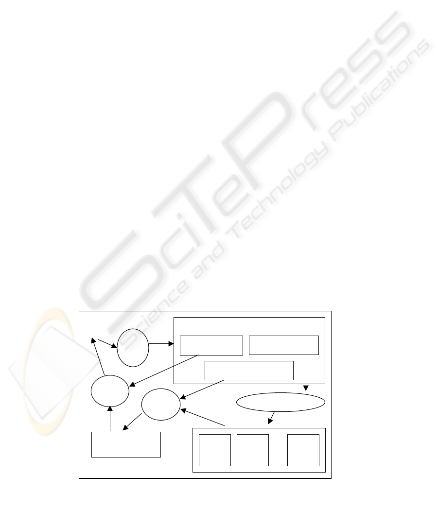
We propose in this work a platform of construction
and analysis of UML models (see figure 1). This
platform offers a user a graphic interface for the
edition of the class, statechart and collaboration
diagrams. The statechart diagrams are converted into
Object colored Petri net Models (OPM) that will be
connected by derivation of the collaboration
diagrams. The Petri nets resulting from the
derivation are then analyzed using some adequate
information on the class diagrams. The analysis is
performed by way of a validator, PROD
(Varpaaniemi, 1997). The results of the verification
can afterwards be exploited for eventual corrections
on the UML model which is likewise refined,
verified and then corrected until reaching the level
of detail sought for the final code generation.
O
bject
RdPc
Model
derivation approach
PROD
analysis
User
UML
diagrams
colored Petri nets
…
O
bject
RdPc
Model
UML
editor
statechart diagram
collaboration diagram
OPM
Link
class diagram
O
bject
RdPc
Model
Figure 1 : Methodology of modeling and analysis
Figure 1: Methodology of modeling and analysis
ICINCO 2004 - INTELLIGENT CONTROL SYSTEMS AND OPTIMIZATION
250
3.1 Object behavior specification
approach
Saldahana and Shatz (Saldhana, 2001) develop a
method of derivation of Petri nets from UML
modeling, based on statechart and collaboration
diagrams. The generated Petri nets, allow the
specification of the operational behavior of the
system.
Such (Saldhana, 2001), we suggest to connect
the statechart models translated into Petri nets, using
the collaboration diagram information. However, we
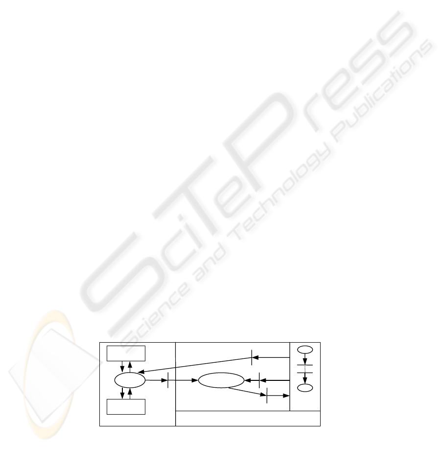
propose a different architecture of interconnection
(see figure 2) and new rules of interaction. The
resulting Petri net model is articulated in
components whose generation is carried out as
follows.
Any statechart diagram is converted into a Petri
net called DM (Dynamic Model).
We distinguish on the statechart diagram,
between five types of actions : the event causing the
transition firing (event), the action executed on a
transition at the entry of the state (transition entry
action), the action generated on entering the state
(entry action), the action generated on exiting the
state (exit action) and the action executed on a
transition at the exit of the state (transition exit
action).
The action is modeled by a token of event type.
This token can be internal or external. The external
token symbolizes the inter-object communication.
As for the internal token, it is generated for an
internal use with the DM.
The communication between the objects of the
system is relayed by the Link place. This connection
is deduced from the collaboration diagrams. The
Link place receives the external events coming from
the different DM and poses in each In-Event place
attached to a DM the events thrown to this DM.
The In-Event place constitutes, the reserve of the
events that are sent to the DM whether they are
external coming from the Link place or internal
generated by the DM itself. It is an interface for the
DM towards the events which occur within. The DM
and this interface constitute an Object Petri net
Model called OPM.
3.2 Object dynamic specification
approach
Our approach, contrary to Saldhana and Shatz’s
technique is not limited to the specification of the
system operational behavior ; it also aims at the
modeling of the dynamics of the objects through the
roles they play. Thus, diagrams translating the
structural schematics of the objects as well as their
movement, must be used to generate Petri nets
supporting a precise specification of these objects.
To this end, we propose to introduce on the one
hand, the class diagram which represents the
structural links between the objects of the system, by
emphasizing the roles they play, and to insert on the
other hand, in the statechart diagram, the evolution
expression of the objects. This expression will be in
charge of the role updates by insertion or
suppression of objects. It will appear as a tagged
value that follows the operation causing the update
of the role. This tagged value will translate the
insertion (
+ role) / suppression (- role), of a given
object in the role (see figure 3).
The role is a pseudo-attribute of the source
class; so, it is important to observe the principle of
its encapsulation in the source class, in order to
remain in conformity with the object interconnection
scheme of figure 2 ; the role updates of a source
class can accompany only the operations of this
class.
DM entr
y
OPM
Link
OPM
OPM
DM
In-Event
Figure 2 : Architecture of a colored Petri net derived from UML
Figure 2: Architecture of a colored Petri net derived from UML
FROM UML TOWARDS PETRI NETS TO SPECIFY AND VERIFY
251

state
entry: action {
±
role()}
do: activity
exit: action {
±
role()}
event {
±
role()} / action {
±
role()}
Figure 3 : Role update expression on the statechart diagram
/ action {±role()}
Fi
g
ure 3: Role u
p
date ex
p
ression on the statechart dia
g
ra
m
This approach strongly supports a precise
verification/validation of the modeling. The
validation can be obtained by way of the awaited
properties of the system, written by the modeler in
the OCL language. OCL is a formal language mainly
based on the handling of collections in order to
specify object invariants. However, these collections
correspond to a specification of roles. So, the use of
OCL implies inevitably, the use of the role concept
modeling. This makes it possible to say that the
validation allows the checking of the object
operational and interactive mode as well as the
object movement through the system, by means of
the roles it plays.
The properties are then translated into the PROD
validator syntax to be checked. The translation of
OCL specification in temporal logic properties,
constitutes the subject of a study which is being
presented into another article. For a deeper
validation, we also propose in that study to introduce
temporal logic operators into OCL.
We present in section 4 some properties of the
system, specified in OCL language and then
translated into PROD temporal logic syntax. The
establishment of the system properties will rely on
the class diagram structure.
3.3 Derivation technique
The derivation of UML modeling to the Petri net
specification, is introduced on : the class diagram for
getting the OCL invariants, the statechart diagram to
translate the object behavior and dynamics and
finally, the collaboration diagram for connecting the
interactive objects of the system.
3.3.1 Derivation from the collaboration diagram
UML object is modeled by a colored token in the
Petri nets. The various colors of the token
correspond to the object arguments. We distinguish
between two types of objects : interactive objects, of
object type, and exchanged objects, of event type.
The exchanged objects are signal or call events.
Therefore, any interactive object is a prototype
object modeled by the token <obj>, where obj is the
object identifier. As far as the event object is
concerned, its source and destination must always
appear in the specification, in order to precise the
entity involved in the interaction. These arguments
are drawn from the collaboration diagram. Thus, the
«send» event is identified by the source object
(srce), the target object (targ), the event identifier
(ev) and the object which undergoes the action
(exobj). It is modeled by the token <srce, targ, ev,
exobj>.
The collaboration diagram is used to connect,
with the Link place (see figure 2), the interactive
objects which it represents and which are translated
into OPM models. The exchanged messages are
external events. All of them forward through the
Link place.
Thus, for each OPM model, an oriented
transition from the Link place to the In-Event place
is built. The transition firing is conditioned by the
external events in entry of the object, on the
collaboration diagram.
Furthermore, all the events exchanged between
two objects are inserted in the In-Event place of the
OPM corresponding to the source object.
Algorithm
– create the Link place,
– for each OPM model deriving from the object
obj :
- create an In-Event place,
- put in the In-Event place all the events <srce,
targ, ev, exobj>, in exit of the object obj,
- create a transition t,
- create an arc Link→t such that Pre(Link, t) =
<srce, obj, ev
1
, exobj> + … + <srce, obj, ev
n
,
exobj> where ev
i
is an entry event of the
object obj,
- create an arc t→In-Event such that Post(t, In-
Event) = <srce, obj, ev
1
, exobj> + … + <srce,
obj, ev
n
, exobj>.
3.3.2 Derivation of the statechart diagram
Since statechart diagrams may contain hierarchical
or nested states, effective conversion to Petri nets
requires that the nested states be flattened. So, for a
given statechart diagram which models the lifetime
ICINCO 2004 - INTELLIGENT CONTROL SYSTEMS AND OPTIMIZATION
252

of an object, one can generate a Shlaer-Mellor object
life cycle (Shlaer, 1992), which is a flat state
machine (contains just simple states and arcs). This
transformation is given in (Saldhana, 2001). Then
the flat state machine can be converted into a
colored Petri net that forms the DM of the OPM
model. This derivation is performed conforming to
the conversion rules that we define below.
The colored Petri net is defined by <P, T, Pre,
Post, M
0
, C> where P is the set of state or role type
places, T is the set of transitions, and C is the set of
colors. Pre and Post are functions related to the
transition firing. M
0
is initial marking.
We indicate in what follows by : e
i
a state i,
<obj> an interactive object, <exobj> the object
which undergoes the action, srce the source object
and targ the target object.
Algorithm
Conversion of a state e
– if final state, nothing to do,
– else create a place of state type,
– if initial state, create a token <obj> defining the
initial marking M
0
.
Conversion of a transition between the e
1
and e
2
states (e
1
–t→e
2
)
– create a transition t,
– create an arc e
1
→t such that Pre(e
1
,t ) = <obj>,
– if e
2
not final state, create an arc t→e
2
such that
Post(t, e
2
) = <obj>.
Conversion of an event ev on the transition t
– create an arc In-Event→t such that Pre(In-Event,
t) = <srce, targ, ev, exobj>.
Conversion of an internal/external entry action
act inside e
2
such that e
1
–t→e
2
– create an arc In-Event→t such that Pre(In-Event,
t) = <srce, targ, act, exobj>,
– create an arc t→In-Event/Link such that Post(t,
In-Event/Link) = <srce, targ, act, exobj>.
Conversion of an internal/external exit action act
inside e
1
such that e
1
–t→e
2
– create an arc In-Event→t such that Pre(In-Event,
t) = <srce, targ, act, exobj>,
– create an arc t→In-Event/Link such that Post(t,
In-Event/Link) = <srce, targ, act, exobj>.
Conversion of an internal/external transition
entry/exit action act on t such that e
1
–t→e
2
– create an arc In-Event→t such that Pre(In-Event,
t) = <srce, targ, act, exobj>,
– create an arc t→In-Event/Link such that Post(t,
In-Event/Link) = <srce, targ, act, exobj>.
Conversion of an insertion in the role r, on the
transition t
– create a place of role type, if the place does not
exist,
– if the role indicates an interactive object and it
follows an event, create an arc t→r such that
Post(t, r) = <srce>,
– if the role indicates an interactive object and it
follows an action, create an arc t→r such that
Post(t, r) = <dest>,
– if the role indicates the object which undergoes
the action, create an arc t→r such that Post(t, r)
= <exobj>.
Conversion of a decrementation of the role r, on
the transition t
– if the role indicates an interactive object and it
follows an event, create an arc r→t such that
Pre(r, t) = <srce>,
– if the role indicates an interactive object and it
follows an action, create an arc r→t such that
Pre(r, t) = <dest>,
– if the role indicates the object which undergoes
the action, create an arc r→t such that Pre(r, t) =
<exobj>.
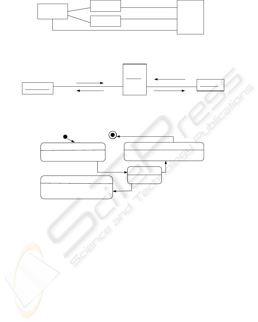
4 CASE STUDY
We illustrate our approach with an application in
which we model the behavior of an object by the
statechart of figure 6. We then, apply to this diagram
the derivation rules we have enunciated, in order to
generate the corresponding colored Petri net,
represented on figure 7.
The treated application is a message server
whose main role is to manage the communication
between the connected stations. All the exchanged
messages must go through it, to be forwarded to the
receiver.
A station can at all times, connect or disconnect
itself from the server. Its connection request is
carried out by sending the connection event. Its
disconnection is required by the disconnection event
(see figure 5). The server confirms the station
connection or disconnection by the okconnection or
okdisconnection events, respectively.
FROM UML TOWARDS PETRI NETS TO SPECIFY AND VERIFY
253
receivedMessage
1
1
serverMessage
Server
1
Figure 4 : Class diagram of the message server
«signal»
Data
transmittedMessage
1
*
*
*
1
1
1
transmitter
receiver
Figure 4: Class diagram of the message server
:transmitter
:Serve
Connected, a transmitter can notify a message by
way of the «send» notification event. The message
entity is modeled by the signal stereotyped class
Data. After receiving a client notification, the server
transmits it by the «send» transmission event, to the
receiver.
As far as the role updates are concerned, we will
be interested particularly in the transmittedMessage,
receivedMessage and serverMessage roles. The
transmittedMessage role is updated by including an
object, {+transmittedMessage()}, after the «send»
notification action, in the transmitter statechart (see
figure 6). The receivedMessage role is updated,
{+receivedMessage()}, after receiving the «send»
transmission event, in the receiver statechart. As for
the serverMessage, it is incremented of an object
{+serverMessge()}, in the server statechart, when
receiving the «send» notification, and decremented
of an object {-serverMessage()}when transmitting
this notification («send» transmission) to the
receiver (see figure 5).
These treatments allow the expression of the
following OCL invariant that translates the
paraphrased property : a receiver r receives all the
sent messages by a transmitter t.
Property expression in OCL
– {«invariant»
r.receivedMessage→includes (obj) implies
t.transmittedMessage→includes (obj)}
– {«invariant»
t.transmittedMessage→size ==
r.receivedMessage→size +
s.serverMessage→size}
Property expression in PROD
– henceforth (eventually
(transmittedMessage >= <obj>))
implies (eventually
receivedMessage >= <obj>))
r
A1/A2 : «send» okconnection()
A4/A5 : «send» okdisconnection()
A1 : «send» connection()
A2/A3.i *[i:=1..n] : «send» notification()
A3/A4 : «send» disconnection()
Figure
:receiver
B1 : «send» connection()
B3/B4 : «send» disconnection()
B1/B2 : «send» okconnection()
B2,A3.i /B3.i : «send» transmission()
B4/B5 : «send» okdisconnection()
5 : collaboration diagram of the message server
entry : «send» notification()
{+transmittedMessage()}
entry : «send» connection()
connected
«send» okconnection()
«send» okdisconnection()
Figure
Figure 5: Collaboration diagram of the message server
entry : «send» disconnection()
disconnection
connection
do : wait
notification
6 : statechart diagram of the transmitter class
Figure 6: Statechart of the transmitter class
ICINCO 2004 - INTELLIGENT CONTROL SYSTEMS AND OPTIMIZATION
254

In-Event
<okc>
notification
connected
transmittedMessage
Link
disconnection
<d>
<i>
<i>
<i>
<okd>
<
d
>
<okc>
<okd>
<n>
<c>
<i> <n>
<i>
<c>
connection
Figure 7 : OPM of the transmitter class
– henceforth (card(transmittedMessage) ==
card(receivedMessage) + card(serverMessage))
The first invariant means that every object that
belongs to the role transmitterMessage will belongs
to the role receivedMessage.
The second invariant means that the cardinality
of the transmittedMessage role is always equal to
the sum of the receivedMessage and serverMessage
cardinalities.
5 CRITICAL DISCUSSION
The current research works deal only with the
behaviour and the interactions of generic objects.
They do not go yet in details of the object dynamics
and identification. The methodology which we
propose, offers to the user the opportunity of
carrying out a meticulous validation of its modeling
by checking the dynamics of the objects through the
various roles they play. The checking of objects
identified by their roles is allowed by means of the
expression of the awaited properties of the system,
written by the modeler in the OCL language. The
properties are then translated into PROD language to
be verified. This enhances the degree of the
validation/verification but it remains insufficient, as
long as it does not permit the specification and the
validation of multiple class instances, identified by
attribute values. We develop this subject in
(Bouabana-Tebibel, 2004), where we show the
benefits of such an approach.
6 CONCLUSION
initial
Légende
: i = transmitter ; c = transmitter, server, «send» connection, obj1 ;
okc = server, transmitter, «send» okconnection, obj2 ; n = transmitter, server, «send» notification, obji ;
d = transmitter, server, «send» disconnection, obj3 ; okd = server, transmitter, «send» okdisconnection, obj4 ;
Figure 7: OPM of the transmitter class
This paper introduces a methodology to specify with
UML, and then to systematically verify and validate
modeling without having to master the techniques of
formal checking. This methodology is founded on a
derivation technique of colored Petri nets from UML
models. The verification and validation are not only
about the object’s behavior, as presented in
(Saldhana, 2001) but also on the object dynamics.
For this purpose, we integrated the class diagram in
the derivation technique and then we proposed to
introduce the modeling of the objects into the
statechart diagram.
To test the practical implementation of our
derivation approach, we built a translator whose
semantic functions are drawn from the rules we have
enunciated. We also developed a graphic interface
for the construction of the class, statechart and
collaboration diagrams. These diagrams constitute
the entry of the translator whose exit results into
colored Petri nets, specified in PROD syntax.
PROD is then executed to verify the modeling.
Among the prospects of this work, the analysis
of the validation/verification results and their
feedback to the user are explored. These results must
be presented to the designer in an interpreted form,
where the error in modeling is simply and clearly
pointed out. Since the methodology calls for UML to
provide the input specifications, it is only reasonable
for the output results to be meaningful to the user.
We also project to derive Petri nets specifying the
operational and dynamic behavior of the objects
from the activity diagrams.
FROM UML TOWARDS PETRI NETS TO SPECIFY AND VERIFY
255

REFERENCES
Attiogbé, C., 2004. «Systematic Derivation of a Validation
Model from a Rule-oriented Model : A System
Validation Case Study using PROMELA/SPIN»,
Proceedings of the 1
st
International Conference on
Information & Communication Technologies : from
Theory to Application – ICTTA’04
, Damas, Syria,
April.
Attiogbé, C., Poizat, P., Salaun, G., 2002. «Integration of
Formal Datatypes within State Diagrams», Technical
Report N°02.3, IRIN, University of Nantes, July.
Bittner, M., Kammüller, F., 2003. «Translating
Fusion/UML to Object-Z»,
1
st
ACM and IEEE
International Conference on Formal Methods and
Models for Co-design – MEMOCODE’03
, ISBN 0-
7695-1923-7/03, IEEE. Mt. St. Michel, France, June.
Bouabana-Tebibel, T., Belmesk, M., 2004. «Formalization
of UML object dynamics and behavior»,
2004 IEEE
International Conference on Systems, Man &
Cybernetics
, The Hague, Netherlands, October 10-13.
Delatour, J., De Lamotte, F., 2003. «ArgoPN : A CASE
Tool Merging UML and Petri Nets»,
1
st
International
Workshop on Validation and Verification of software
for Enterprise
Information Systems, in ICEIS, Angers,
April.
Elkoutbi, M., Keller, R. K., 2000. «User Interface
Prototyping based on UML Scenarios and High-level
Petri Nets»,
21st International Conference on
Application and Theory of Petri Nets ICATPN 2000
,
Aarhus, Denmark, LNCS, vol 1825, Pages 168-186,
Springer-Verlag.
Jensen, K., 1992.
Coloured Petri nets, Vol 1: Basic
Concepts
, Springer-Verlag.
Kim, S.-K., Carrington, D., 1999. «Formalizing The UML
Class Diagram Using Object-Z»,
UML’99 – The
Unified Modeling Language Beyond The Standard
,
Second International Conference, Fort Collins, CO,
USA, October 1999, LNCS vol. 1723, Springer.
Kuske, S., 2001. «A formal semantics of UML state
machines based on structured graph transformation»,
In M. Gogolla and C. Kobryn, ed. UML: The Unified
Modeling Language. Modeling Languages, Concepts
and Tools, volume 2185 of LNCS, pages 241-256.
Springer.
Lilius, J., Paltor, I., 1999. «
vUML a tool for verifying
UML models»,
Proceedings ASE’99, IEEE Computer
Society, pp. 255-258.
Meyer, E., 2001. Développement formels par objets :
utilisation conjointe de B et d’UML. PhD thesis,
LORIA, University of Nancy 2.
Object Modeling Group., 2001.
Unified Modeling
Language Specification
, version 1.4, September.
Roe, D., Broda, K., Russo, A., 2003. «Mapping UML
Models incorporating OCL Constraints into Object-
Z», Imperial College Technical Report N°2003/9,
September.
Saldhana, J. A., Shatz, S. M., 2001. «UML Diagrams to
Object Petri Net Models : An Approach for Modeling
and Analysis»,
PDCS’2001. 14th International
Conference on Parallel Systems, Uml and Petri nets
relations and distributed computing systems,
Las
Vegas, April.
Shalaer, S., Mellor, S. J., 1992.
Object life cycles –
Modeling the world in states
, Yourdon Press, Prentice
Hall.
Telelogic, 2003. UML Suite and SDL Suite
documentation
, , http://www.taug2.com/
Varpaaniemi, K., Halme J., Hiekkanen K., Pyssysalo T.,
1997.
PROD Reference Manuel, Helsinki University
of Technology, Digital Systems Laboratory, Finland.
Varro, D., 2002. «A Formal Semantics of UML
Statecharts by Model Transition Systems»,
ICGT’02,
Proc. of the 1
st
International Conference on Graph
Transformation
, Spain.
ICINCO 2004 - INTELLIGENT CONTROL SYSTEMS AND OPTIMIZATION
256
