
Pain-mitigation Techniques for Model-based Engineering using
Domain-specific Languages
Benny Akesson
1
, Jozef Hooman
1,2
, Roy Dekker
1,3
, Willemien Ekkelkamp
1,3
and Bas Stottelaar
4
1
Embedded Systems Innovation by TNO, Eindhoven, The Netherlands
2
Radboud University, Nijmegen, The Netherlands
3
Thales Nederland, Hengelo, The Netherlands
4
Altran, Eindhoven, The Netherlands
Keywords:
Model-based Engineering, Domain-specific Languages, Simulation, Validation, Threat Ranking.
Abstract:
Changing an established way of working can be a real headache. This is particularly true if there are high
stakes involved, e.g., when changing the development process for complex systems. New design methods,
such as model-based engineering (MBE) using domain-specific languages (DSLs) promise significant gains,
such as cost reductions and improvements in productivity and product quality. However, transitioning between
design methods comes with a great deal of uncertainty, as any approach has associated pains. While the gains
may be intuitively appreciated, it may be less clear what the new pains will be and whether or not they will
cancel out the gains. For this reason, it may sometimes feel safer to stick with the devil you know than to meet
the one you do not, preventing the full design potential of the company from being reached.
This paper is an experience report from an investigation into how to mitigate the pains associated with a
transition to a model-based design flow using DSLs. The main contributions of the paper are: 1) a list of
14 pains related to MBE as a technology that is representative of our industrial partners designing high-tech
systems in different domains, 2) a selected subset of six pains is positioned with respect to the state-of-the-
practice, 3) practical experiences and pain-mitigation techniques from applying a model-based design process
using DSLs to an industrial case study, and 4) a list of three open issues that require further research.
1 INTRODUCTION
As systems get increasingly complex, design times go
up and it becomes harder and more time-consuming
to react to frequent changes in requirements or in-
troduction of new technology. In most current
document-based design flows, there is only limited
reuse between different stages of design, increasing
design time. Changes often result in confusing in-
consistencies between different component artifacts,
such as simulation models, production code and doc-
umentation. These issues can be tackled by a model-
based engineering (MBE) approach using domain-
specific languages (DSLs), where the different arti-
facts, can be generated and quickly regenerated from
a domain-specific model, being the sole source of
truth (Smith et al., 2007). This helps reducing de-
sign time and improves the evolvability of the system,
as changes only have to be made in a single place,
and consistency between artifacts is ensured as they
are regenerated. While this makes the approach intu-
itively promising, it comes with its own set of associ-
ated pains. It is hence essential for a company to think
carefully about the strengths and weaknesses of their
organization and processes before transitioning their
design flow to make sure that the pains do not offset
the gains (Smith et al., 2007; Whittle et al., 2014).
This paper is an experience report about first steps
towards transferring a model-based design approach
using DSLs to a company in the defense domain. The
scope of this work is limited to investigating the pains
and possible mitigation techniques to assert that there
are no immediate show-stoppers. Based on this in-
vestigation, the company will decide whether to take
further steps towards a transfer. This work is success-
ful if it helps the company make the right decision for
how to proceed, no matter which decision this is.
The company has a largely document-based de-
sign flow, but uses a variety of models in different
languages and at different levels of abstraction dur-
ing the design process. For instance, different model-
ing techniques are used during early design-space ex-
752
Akesson, B., Hooman, J., Dekker, R., Ekkelkamp, W. and Stottelaar, B.
Pain-mitigation Techniques for Model-based Engineering using Domain-specific Languages.
DOI: 10.5220/0006749707520764
In Proceedings of the 6th International Conference on Model-Driven Engineering and Software Development (MODELSWARD 2018), pages 752-764
ISBN: 978-989-758-283-7
Copyright © 2018 by SCITEPRESS – Science and Technology Publications, Lda. All rights reserved

ploration and detailed performance estimation in later
phases. To reduce design time, it is desired to im-
prove the continuity and reuse between the stages of
the design process by creating an explicit relation be-
tween the different artifacts of a component. This will
also make it easier to ensure the consistency between
models at different levels of abstraction and their cor-
respondence to the final implementation.
The four main contributions of this paper are: 1)
a list of 14 pains related to MBE that is represen-
tative of our industrial partners designing high-tech
systems in different domains. This list is useful for re-
searchers and practitioners aiming to transfer or adopt
model-based technologies, 2) a subset of six pains is
positioned with respect to the state-of-the-practice to
determine whether or not the pain is generally rec-
ognized in the literature and what the known pain-
mitigation techniques are, 3) practical experiences
and results from applying a model-based design pro-
cess using DSLs that minimizes the anticipated pains
and provides continuity and reuse between design
phases in an industrial case study of a Threat Rank-
ing component, and 4) a list of three open issues that
require further research is presented, which may help
guide future research in this area.
The rest of this paper is organized as follows. Sec-
tion 2 presents the list of pains related to MBE and
we choose six of these for further consideration in this
work. Section 3 discusses the state-of-the-practice for
the selected pains, before we continue in Section 4 by
explaining our choice of technology, case study, and
method for our practical investigation. The Threat
Ranking DSL developed as a part of this work is pre-
sented in Section 5, after which we discuss the results
from applying it to the selected pains in our case study
in Section 6. Open issues are presented in Section 7,
followed by conclusions in Section 8.
2 PAINS AND GAINS
The first step in this work is to identify the pains and
gains relevant to MBE. Inspiration for these pains and
gains is primarily taken from management processes,
engineering practices, and interactions with experi-
enced people from partner companies in different do-
mains in the high-tech industry, e.g., defense, health-
care and manufacturing. This work focuses on pain-
mitigation techniques for MBE and does not intend to
present the identified gains for brevity. For empirical
studies discussing the benefits of MBE and its indus-
trial impact, refer to e.g., (Vetro et al., 2015; Torchi-
ano et al., 2013; Melleg
˚
ard et al., 2016). Note that the
presented pains are not laws of nature that apply to
all situations, but may also include concerns and ob-
jections from people who are just not convinced about
the merits of MBE. Some of the pains are furthermore
not exclusive to MBE, but are still raised in the con-
text of a potential technology transfer. The presented
list of pains is hence useful to any practitioner trying
to transfer or adopt MBE technology, or academics
that need to position their work with respect to indus-
trial concerns.
The 14 pains below are related to MBE in a broad
sense without considering a particular tool or method.
The term model can hence refer to e.g., UML di-
agrams, DSL instances, and executable (simulation)
models. It is important to recognize that introducing
MBE in a company is not just a matter of technol-
ogy, but is also widely recognized as an organizational
and social challenge (Hutchinson et al., 2014; Whit-
tle et al., 2014; Baker et al., 2005; Wile, 2004; Smith
et al., 2007). However, these aspects are out of scope
of this paper.
1. No continuity in the development process (“if ev-
erybody has their own tools or only covers part of
the problem, there is no continuity in the process”)
2. No proper modeling strategy (“models cannot
solve everything; one needs to define goals /
strategies for the modeling”)
3. No management of tools (“different versions,
backwards compatibility, etc.”)
4. Too much dependency on tools (“more tool ven-
dors - which may go bankrupt or are taken over
- and more tool versions increase the possibility
that models become unsupported or obsolete”)
5. Difficult to deal with many possible system con-
figurations (“many possible system configura-
tions, because there are many optional compo-
nents, many different instances of components,
many different connections between components
- how to model, test and simulate them?”)
6. Issues and large effort when interfaces of compo-
nents change (“how to deal with changing inter-
faces; consequences for the model, architecture,
etc.?”)
7. Difficult to deal with different versions of a com-
ponent, variability within a component, and dif-
ferent models of a single component (“how to
deal with different versions and models of com-
ponents?”)
8. No consistency between model and realization
(“the model has to represent the product correctly;
if the product changes, this has to be reflected in
the model”)
Pain-mitigation Techniques for Model-based Engineering using Domain-specific Languages
753

9. No consistency between models and documenta-
tion (“how to keep documents up-to-date after fre-
quent changes to the model?”)
10. Incorrect models (“how to ensure that the model
is correct and gives the right outcome?)”
11. Large maintenance effort of models and gener-
ators (“how to arrange maintenance of models /
generators?”)
12. Code generation leads to low quality code (“what
is the quality of generated code?”)
13. Integration and testing of code, generated code,
and models is difficult (“do the generated simu-
lation models, generated code, and existing code
work together properly?”)
14. Confusion about the relation between results and
versions of component models & tools (“keep
track of input, versions, output, description of the
models, etc.”)
While all the pains represent valid concerns, we
choose to focus on a subset of six pains that are most
relevant to the company, our case study, and the con-
sidered modeling technology. However, since there
is some overlap between the different pains, we will
briefly touch upon a few others. The main considered
pains are Pains 1, 7, 8, 10, 12, and 14.
3 STATE-OF-THE-PRACTICE
After selecting a subset of six pains for further con-
sideration in this work, this section continues by posi-
tioning them with respect to the state-of-the-practice,
i.e. empirical studies, case studies, and best practices
in industry. We choose this focus to limit the discus-
sion to relevant industrial problems and proven solu-
tions. A broader exploration including academic so-
lutions is highly relevant, but is left as future work.
For Pains 1 and 14, we have not found relevant re-
lated work in an industrial context. In the rest of this
section, we hence focus on Pains 7, 8, 10 and 12.
3.1 Different Models of a Component
and Different Grammars (Pain 7)
Different versions of a component can be managed
using existing source code control systems, such as
Subversion or Git, which allow changes to be tracked
between revisions and any revision can be retrieved
from the system at any time. This approach works
particularly well if the component-definition is text-
based, which is the case for source code and many
types of DSL instances.
Variability within a component can be addressed
using feature models (Beuche et al., 2004). However,
a limitation of feature models is that they are context-
free grammars that can only specify a bounded space
that is known a priori. This means that feature
models are suitable for configuration, i.e., selecting
a valid combination of features that are known up
front (Voelter and Visser, 2011). However, it is not
possible to use a feature model to specify new features
that were not previously considered at an abstract
level. If this is necessary, an alternative approach is
to specify variability using general-purpose program-
ming languages, which are fully flexible, but expose
low-level implementation details and do not separate
problem space and solution space. DSLs bridge the
gap between feature models and general-purpose pro-
gramming languages, as they are recursive context-
free grammars that can specify new behavior from an
unbounded space, while keeping problem space and
solution space separate (Voelter and Visser, 2011).
DSLs hence seem like a promising technology for
evolving systems with variability. However, while
DSL technology may conveniently address the evolv-
ability of components, a new challenge is to manage
the evolution of the DSL itself, its generators, and
models.
3.2 Consistency between Model and
Realization (Pain 8)
Consistency between models and realization (or other
artifacts) is a pain, unless it can be bridged by means
of generation from a single source. In fact, this way of
working is considered a best practice of MBE (Smith
et al., 2007) and is a key benefit of MDE approaches
that easily and efficiently support generation, which
is a core purpose of DSLs. This benefit was explicitly
highlighted in (Melleg
˚
ard et al., 2016), where both
code and documentation were generated from mod-
els specified using DSLs. This means that the model
was always consistent with the generated artifacts.
Similarly, (Kurtev et al., 2017) generates a simulation
model, C++ code, visualizations, run-time monitoring
facilities, and documentation that is consistent with
an interface description based on a family of DSLs.
These works suggest that DSLs is a good choice of
technology for our requirement of supporting multi-
ple environments in a consistent manner.
3.3 Ensuring Model Quality (Pain 10)
If models are used as the sole source of truth and the
source of all generated artifacts, it is essential to val-
idate models to ensure their correctness. In addition,
MOMA3N 2018 - Special Session on Model Management And Analytics
754

it is frequently stated as a best practice to test and
find defects as early as possible (Voelter, 2009), since
this has been shown to increase quality and reduce the
total time and effort required to develop or maintain
software (Melleg
˚
ard et al., 2016; Broy et al., 2012).
There are several ways to improve the quality of
models and ensure correctness. One best practice is
to review models, just like any other piece of soft-
ware (Voelter, 2009). This is currently done by many
practitioners to build confidence in the quality of code
generators and the generated code (Broy et al., 2012;
Mooij et al., 2013). In (Baker et al., 2005), the quality
and correctness of models is established by simulating
the models against an executable test suite. Another
best practice is to use model-level validation (Voelter,
2009) to verify that the model is a valid instance of
the language, but perhaps more importantly, to vali-
date that the model makes sense in the domain where
it will be used.
3.4 Quality of Generated Code (Pain 12)
This pain is phrased rather broadly, since software
quality can mean a lot of different things (Interna-
tional Organization for Standardization, 2011). A ter-
tiary study, i.e., a study of literature surveys, in the
area of quality in MBE is presented in (Goul
˜
ao et al.,
2016). The study considers as many as 22 litera-
ture surveys, many of which choose maintainability
as the quality metric of choice. They conclude that
the field is not yet fully mature as most surveys tar-
get researchers and focus on classifying work, rather
than targeting industry practitioners and aggregating
quantitative evidence according to established quality
metrics. We proceed by discussing a few relevant pri-
mary studies, most of which conclude that quality of
generated code is actually a gain rather than a pain.
A case study (Melleg
˚
ard et al., 2016) in the Dutch
IT-industry showed that introducing MBE in the
maintenance phase of a software project can improve
software quality. More specifically, they showed that
a lower defect density was achieved using modeling,
although at the expense of increasing time to fix a de-
fect. However, the total result of these effects was
a decrease in the total effort spent on maintenance of
versions of the software. A reduction of defects is also
observed in (Mohagheghi and Dehlen, 2008), but it is
not supported by any quantitative evidence. A similar
observation was made by Motorola in (Baker et al.,
2005), which states that it is sometimes faster and
sometimes slower to find the root cause of a software
defect when using MBE. They also provide quantita-
tive estimates suggesting a reduction in the time to fix
defects encountered during system integration, over-
all reduction of defects, and improvements in phase
containment of defects (i.e. that defects are more
likely to be detected and fixed in the development
phase in which they are introduced) and productivity.
Another aspect of generated code quality is the ex-
tent to which it is readable by humans. Best prac-
tices state that generated code should follow accept-
able style guides. This may seem like a waste of
time, since other best practices suggest that generated
code should not be modified (Voelter, 2009). How-
ever, people still interact with generated code in sev-
eral ways. For example, just like for any other code,
generated code is inspected by developers trying to
track down the root cause of a defect and this goes
faster if it is clear what the code is doing. Secondly,
manual code reviews of generated code are part of the
development practice in many places to ensure cor-
rectness of the code and its generators (Broy et al.,
2012; Mooij et al., 2013). Since code generators gen-
erate code in a structured way, this means that the
confidence in their correctness is increased over time.
This argument is consistent with a best practice stated
in (Voelter, 2009). Lastly, for certification of safety-
critical software in e.g., the automotive and avionics
domains (RTCA, Inc., 2012), it may furthermore be
more cost-efficient to manually inspect the code than
to qualify the code generator, which is very expensive
and time-consuming.
4 APPROACH TO INVESTIGATE
MITIGATION OF PAINS
This section explains the organization of the practi-
cal investigation of the pains for an MBE approach
based on DSLs in an industrial case study. We start
by motivating our choice of modeling technology, be-
fore presenting the case study. Lastly, we present our
approach to investigate pain-mitigation techniques.
4.1 Modeling Technology
The potential pains of MBE are investigated by means
of DSLs, since the discussion in Section 3 suggests
that it has the potential to successfully mitigate many
of the chosen pains. It is also a technology that is al-
ready used within the partner company, and we have
many years of experience of transferring it to indus-
try and applying it, e.g., (Kurtev et al., 2017; Mooij
et al., 2016). There are many approaches (Mernik
et al., 2005) and tools (Erdweg et al., 2015) for de-
veloping DSLs. This work uses Xtext as DSL devel-
opment tool. Xtext is a mature language workbench
that has been around for more than a decade and has
Pain-mitigation Techniques for Model-based Engineering using Domain-specific Languages
755
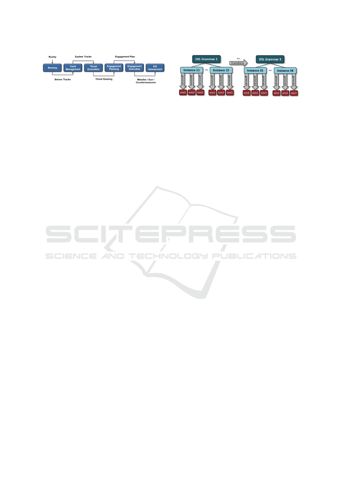
Figure 1: Overview of the engagement chain.
high coverage in terms of important features for lan-
guage development (Erdweg et al., 2015). Xtext is
additionally an open-source tool, which is available as
a plugin for the Eclipse IDE. Generators are defined
in the Xtend language, which is a DSL built on top
of Java that can be combined with regular Java code.
Details on how to develop DSLs and generators based
on Xtext and Xtend can be found in (Bettini, 2016).
4.2 Case Study
A suitable case study is needed to investigate pain-
mitigation techniques. We start by presenting the gen-
eral context of our case study, being the engagement
chain of a Combat Management System, shown in
Figure 1. This work considers a single ship, referred
to as the own ship, with a number of sensors, e.g.,
surveillance radars and tracking radars, and a number
of effectors, such as missiles, guns, and countermea-
sures.
The engagement chain consists of a number of
steps that execute periodically, e.g., every few sec-
onds. In the first step, surveillance radars are ob-
serving their environment and produce sensor tracks,
which can be intuitively understood as a radar blip
with a position and speed corresponding to e.g., an-
other ship, a missile, or a jet. The sensor track is then
passed on to a track management process that fuses
sensor tracks from multiple sensors to generate a sin-
gle, more accurate, system track. The detected set of
system tracks are sent to the threat evaluation process,
which determines the type of threats and produces a
ranking that indicates which threat is considered more
dangerous. A list of ranked threats is then sent to
the engagement planning process, which determines
the combinations of sensors and effectors that should
be used against each hostile threat and at what time,
i.e., planning in both time and space. Depending on
the choice of planning algorithm, it may plan engage-
ments of threats strictly following threat ranking, or it
may plan more flexibly using the ranking as a guide-
line. The generated engagement plan is then executed,
followed by a kill assessment process that determines
whether the threat has been neutralized or should be
considered for reengagements.
For the purpose of our case study, we have se-
lected the Threat Ranking component, which is the fi-
nal step of the Threat Evaluation process. In essence,
Figure 2: Overview of approach.
the Threat Ranking component gets a list of hostile
threats and produces an ordered list of threats indi-
cating the priority with which they should be consid-
ered for engagement by the engagement planner. This
ranking can be produced in many ways using a wide
range of different criteria that can be expressed as in-
stances of a DSL. Threat Ranking is considered a suit-
able choice for our case study as it is a relatively small
component, yet with sufficient variability to be inter-
esting to model using a DSL. The size of the com-
ponent is beneficial as it can be modeled with limited
time, allowing multiple iterations of development, an-
other best practice from (Voelter, 2009).
4.3 Organization of Investigation
The chosen modeling approach is applied to three
phases of development with different target environ-
ments: 1) early design space exploration to identify
candidate system configurations, where high-level
simulation models of components are used to provide
quick approximate results, 2) detailed performance
estimation using high-fidelity simulation models to
get accurate results for a single or a few candidate
systems, and 3) execution of production code in the
actual Combat Management System. Note that the
Threat Ranking component runs a relatively simple
algorithm that can be fully implemented in all three
environments. This means that unlike e.g., a radar
model, the different implementations of the Threat
Ranking component do not have different levels of
abstraction. The expectation is hence that all imple-
mentations of the algorithm should output the same
ranking, given the same input and environment.
To capture the impact of an evolving language, we
choose to design and implement the Threat Ranking
DSL in three steps. First, we create a baseline gram-
mar with basic Threat Ranking concepts. We then
extend this grammar twice and introduce additional
concepts. More details about each of the three DSL
grammars is provided in Section 5. An overview of
our approach is shown in Figure 2, which shows sev-
eral versions of the grammar, each with a number of
model instances that have to be mapped to each of the
three environments.
MOMA3N 2018 - Special Session on Model Management And Analytics
756
5 THREAT RANKING DSL
This section presents the Threat Ranking DSL devel-
oped in this work. As previously mentioned in Sec-
tion 4.3, we first define a baseline grammar (referred
to as Grammar 1) with basic Threat Ranking con-
cepts. This grammar is then extended twice, resulting
in Grammars 2 and 3, respectively, adding new con-
cepts that increases the range of algorithms that can
be expressed in the language.
Note that for reasons of confidentiality, the Threat
Ranking process modeled in this work does not im-
mediately correspond to any Threat Ranking compo-
nent produced by the company, but captures the gen-
eral spirit and complexity of such a component. Also
remember that the goal of this work is to investigate
pain-mitigation techniques for the selected pains and
not to design the perfect DSL. The DSL presented in
this section is hence only means to achieve the goal.
Next, we proceed by presenting each of the three
grammars in more detail. Note that this is an overview
and not a complete reference manual for the language.
The following descriptions hence only cover key con-
cepts and not the full expressivity of the DSL.
5.1 Design Rationale
In terms of the classification of DSL development pat-
terns in (Mernik et al., 2005), this work used informal
domain analysis, primarily based on discussions with
relevant domain experts, to identify a suitable domain
model. The design of the language was initially infor-
mal and followed the language invention pattern, i.e.,
a new DSL was designed from scratch. The design
process primarily involved making a number of ex-
ample instances demonstrating relevant use-cases at
a suitable level of abstraction. This was succeeded
by a formal design phase where the concrete syntax
of the language was specified in Backus-Naur form
(BNF), which is the starting point for DSL design in
Xtext. In terms of implementation pattern, we used
the compiler / application generator approach to trans-
late constructs of our DSL to existing languages. This
choice of implementation pattern was motivated by
the desire to enable analysis and validation of DSL
instances, as well as being able to tailor the notation
to the specific domain. In that sense, the choice of
implementation pattern is consistent with recommen-
dations in (Mernik et al., 2005). A design decision of
the language is that it should read well as text to make
it easy for domain experts to understand and discuss.
This means some extra keywords have been added to
make it read better, at expense of slightly longer spec-
ifications. This is not expected to be an issue as spec-
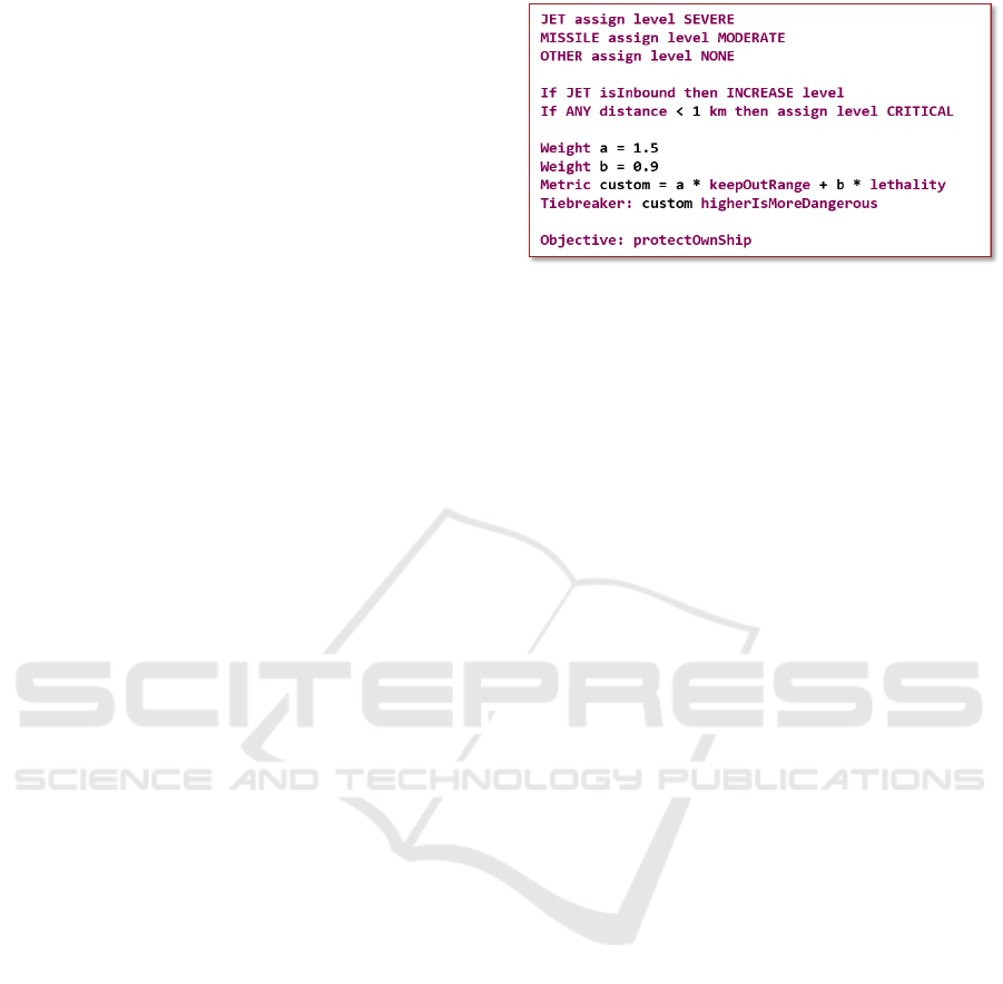
Figure 3: An example instance using Grammar 3 of the
Threat Ranking DSL.
ifications are quite short.
The basic idea behind our Threat Ranking DSL
is to assign priority levels to each threat and to use a
tiebreaker metric to resolve the order in which threats
with the same priority level are ranked. This can
be observed in the example instance shown in Fig-
ure 3. The example is an instance of Grammar 3 of the
Threat Ranking DSL and will be discussed through-
out this section.
5.2 Grammar 1 - Basic DSL Concepts
As seen in Figure 3, instead of using numbers to in-
dicate priority, we use six threat levels, going from
higher to lower: CRITICAL, SEVERE, SUBSTANTIAL,
MODERATE, LOW, and NONE. The first five levels
(CRITICAL to LOW) indicate threats that will appear
in the output threat ranking, while threats with the last
level (NONE) are filtered out and are not considered
for engagements. The benefit of this use of threat lev-
els over priority levels represented by numbers is that
it ties into an existing classification that is used in the
domain, which is commonly considered a best prac-
tice (Voelter, 2009; Karsai et al., 2014; Wile, 2004)
Threat levels are assigned in two ways in the lan-
guage: 1) statically per threat type (e.g., JET and MIS-
SILE), and 2) dynamically per individual threat. The
static assignment associates each threat type with a
threat level that initially applies to all threats of that
type. The proposed DSL requires all threat types to
have a statically assigned threat level and is hence a
common feature among all instances. To facilitate this
in a simple way without explicitly listing all 10 cur-
rently supported threat types, the types OTHER and
ANY have been introduced. ANY covers all types,
whereas OTHER captures all threat types that have not
been listed (i.e., neither explicitly or by an ANY).
The static threat level assignment can be dynami-
cally modified per threat during each execution of the
Threat Ranking algorithm based on properties of the
threat at that particular time, e.g. kinematic informa-
Pain-mitigation Techniques for Model-based Engineering using Domain-specific Languages
757

tion or the distance to the own ship. This is done us-
ing optional if-statements, making this a variable fea-
ture of the language. Values representing distances,
speeds or times are required to have an appropriate
unit to improve readability and remove ambiguity that
can lead to costly mistakes. A number of units are
available in each category, allowing the user to choose
whatever feels more natural. Behind the scenes, the
generators convert all values into common units, i.e.
meters for distances, seconds for time, and meters per
second for speed.
The DSL instance in Figure 3 contains two ex-
amples dynamic threat level modifications. First, it
states that any inbound jet, i.e., a jet flying towards the
own ship, should have its threat level increased by one
step, i.e., from SEVERE to CRITICAL in this case. This
is an example of a relative threat level assignment,
as the resulting threat level depends on the level be-
fore this assignment. Secondly, it states that any threat
that is less than 1 km from the own ship should have
its level reassigned to CRITICAL. This is an absolute
threat level assignment that is independent of the pre-
vious threat level. It is possible to have any number
of if-statements and they are executed in order. If a
relative INCREASE or DECREASE of the threat level
is done on a threat with the highest or lowest threat
level, respectively, the level remains unchanged.
All threats will be assigned a final threat level
based on the combination of static and dynamic threat
level assignments. To arrive at a final ranking, the or-
der in which to rank threats with the same threat level
must be decided. This is done by choosing any of 9
pre-defined tiebreaker metrics, including the distance
from the threat to the own ship and the time to reach
the closest point of approach (assuming a predicted
trajectory). For each metric, it is possible to indicate
whether a higher or a lower value is more danger-
ous. If this parameter is omitted, the default setting
is that a lower value is more dangerous, since this in-
tuitively holds for all pre-defined tiebreaker metrics
except the speed of the threat. It is also possible to
omit the tiebreaker metric altogether, in which case
ties are broken in an unspecified way.
5.3 Grammar 2 - Threat Properties and
Custom Metrics
The second DSL grammar extends the first in two
ways. First, it adds additional static threat proper-
ties, such as the specified keep-out range and the es-
timated lethality of the threat. This means a number
of new keywords were added to the language that re-
moves the need for hard coding important values for
properties in the DSL instance, as done with the keep-
out range of 1 km for the type ANY in the example
instance in Figure 3. Instead, the keywords can be
used directly in the language, see e.g., the use of the
keyword keepOutRange further down in the exam-
ple, and the correct values are automatically provided
to the simulation models or code when they are (re-
)generated. This ensures that important properties can
be modified in a single place in the generator, making
it easier to accommodate changes.
The second addition allows custom tiebreaker
metrics to be defined, vastly increasing the possibili-
ties for how to rank threats with the same threat level.
The example instance in Figure 3 defines a new met-
ric as a weighted combination of the specified keep
out range and the lethality of the threat type. For this
metric, a higher value is more dangerous, as indicated
in the definition of the tiebreaker metric.
5.4 Grammar 3 - High-value Units
The third grammar adds the concept of a High Value
Unit (HVU), which is a critical unit, e.g., a cargo ship
or an aircraft carrier, that may require protection by
the own ship. The DSL is extended with the ability to
specify an objective related to an HVU, i.e., to protect
the HVU, protect the own ship, or protect both. The
introduction of the objective means that the ranking
process is generalized from considering every threat
and its relation to the own ship to consider the relation
to a number of reference tracks. If the objective is
to protect the own ship, then the own ship is used as
reference track to compute e.g., the time to reach the
closest point of approach. Similarly, if the objective is
to protect an HVU, then the HVU is used as reference
track. In case the objective is to protect both, then
they are both used as reference tracks, resulting in a
tiebreaker metric for each reference. These metrics
are then weighed to arrive at a final ranking.
6 RESULTS OF INVESTIGATION
This section explains the pain-mitigation techniques
employed and lessons learned from applying an MBE
approach using DSLs to the case study with the goal
of addressing the six selected pains. We proceed by
discussing each of the selected pains in turn.
6.1 Different Models of a Component
and Different Grammars (Pain 7)
Variations within components are specified com-
pletely within the DSL and do not include the use
of feature models. In fact, the custom metrics in our
MOMA3N 2018 - Special Session on Model Management And Analytics
758
DSL can specify arbitrarily complex expressions con-
taining kinematic information (e.g., speeds and dis-
tances) and other threat properties, which form an un-
bounded space of behaviors that cannot be captured
by feature models. This is a key argument for model-
ing the Threat Ranking algorithms using DSLs.
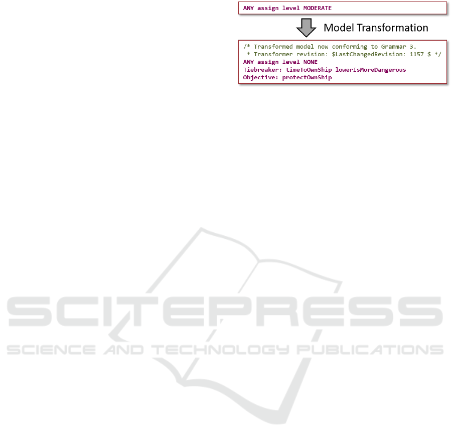
In our evolving DSL grammars, previously dis-
cussed in Section 5, we ensured that new concepts are
optional and have default values when required if they
are not specified. This is mentioned as a best practice
for evolvable languages in (Voelter, 2009). This de-
sign implies that an instance of Grammar 1 is also a
valid instance of Grammar 2 and Grammar 3. For ex-
ample, an instance of Grammar 1 does not use any of
extra static properties that are specified in Grammar 2,
e.g., keep-out range and lethality, and is hence unaf-
fected by their addition when the grammar is extended
to Grammar 2. Similarly, it does not define an op-
tional custom metric, but uses one of the pre-defined
tiebreaker metrics from Grammar 1, which are still
available in later versions of the grammar. Grammar 3
does introduce and require the concept of objective to
produce a ranking, but uses a default setting to protect
the own ship if it is not specified, which was the stan-
dard behavior in earlier versions of the DSL. In this
way, the behavior of instances specified under Gram-
mar 1 and Grammar 2 still behave as expected in the
extended Grammar 3.
While extending a grammar with optional compo-
nents and default settings is simple and convenient, it
may not be possible, or even desirable, in all cases.
For example, this would never allow the concrete
syntax of existing constructs to be modified and im-
proved, which may be very limiting for a DSL that
needs to evolve over long periods of time. A gen-
eral solution to address this problem is to use model
transformations that transform models of an earlier
version of the grammar to a newer version. Imple-
menting a model transformation is no different from
implementing a generator that produces a simulation
model or production code, since they are all examples
of text generation. In this particular case, the gen-
erated text is just an instance of a newer version of
the DSL. A simple example of a model transforma-
tion implemented in this work is shown in Figure 4.
This transformation accepts instances of Grammar 1,
Grammar 2 or Grammar 3 and outputs an instance
compliant with Grammar 3, where all default settings
are made explicit. For example, it explicitly writes
out that the default tiebreaker metric in the imple-
mentation is the time to reach the own ship, where a
lower value is considered more dangerous. Note that
the transformed model clearly indicates which ver-
sion of the grammar it is compliant with and which
Figure 4: A minimal model is transformed to be compatible
with Grammar 3 of the Threat Ranking DSL.
source code revision of the transformer was used to
create it. This helps managing the evolution of the
language (Voelter, 2009).
6.2 Consistency between Model and
Realization (Pain 8)
In the proposed DSL-based approach to MBE, the
model is the sole source of truth from which both
simulations models and code are generated, following
the best practice from (Smith et al., 2007). This was
achieved by implementing code generators for the rel-
evant languages and simulation models are hence al-
ways consistent with each other and with the produc-
tion code. We do currently not any generate documen-
tation, but an additional generator could be imple-
mented to generate documentation using L
A
T
E
X. There
are also available tools for automatic generation of
Word documents, e.g. Gendoc and m2doc. However,
we leave this as future work.
6.3 Ensuring Model Quality (Pain 10)
In the proposed DSL-based approach to MBE, the
model is the sole source of truth from which both sim-
ulations models and code are ultimately generated,
following the best practice from (Smith et al., 2007).
It is hence important that the quality of these models
is high and that any problems are detected as early as
possible. Towards this, we experimented with three
ways to improve model quality:
1. The Eclipse-based IDE for the Threat Ranking
DSL, which is automatically generated from the
DSL grammar by Xtext, ensures syntactic correct-
ness and immediately complains if the syntax of
an instance does not comply with the grammar.
2. A number of model validation rules have been im-
plemented that exploit knowledge about the do-
main to detect problems with instances. These
validation rules can either lead to warnings, which
only alert the user but still allows generation of
artifacts, or to errors, which prevent the genera-
tors from running altogether until the problem is
Pain-mitigation Techniques for Model-based Engineering using Domain-specific Languages
759
resolved. This is generally a good place to ad-
dress deprecation issues as the DSL is evolving.
A warning can be triggered when a deprecated
construct is encountered in a model, assuming an
appropriate model transformation is available to
map it to an equivalent construct in the current
version of the grammar. In contrast, if a model
transformation is not available (anymore), an er-
ror is triggered.
More specifically for our Threat Ranking DSL,
one validation rule triggers a warning if there are
multiple static threat level assignments to a sin-
gle threat type to alert the user that only the last
assignment is useful. In contrast, another rule
throws an error in case not all threat types have a
static threat level assignment, since this violates a
fundamental assumption of the ranking algorithm.
Yet another validation rule checks the correctness
of units, i.e., that metrics related to time or dis-
tance are only compared to values whose units re-
late to time and distance, respectively. This pre-
vents comparing apples to pears, or more literally,
seconds to meters by raising an error. For many of
these validation rules, quick fixes were built into
the editor to help the developer resolve violations
quickly and reliably.
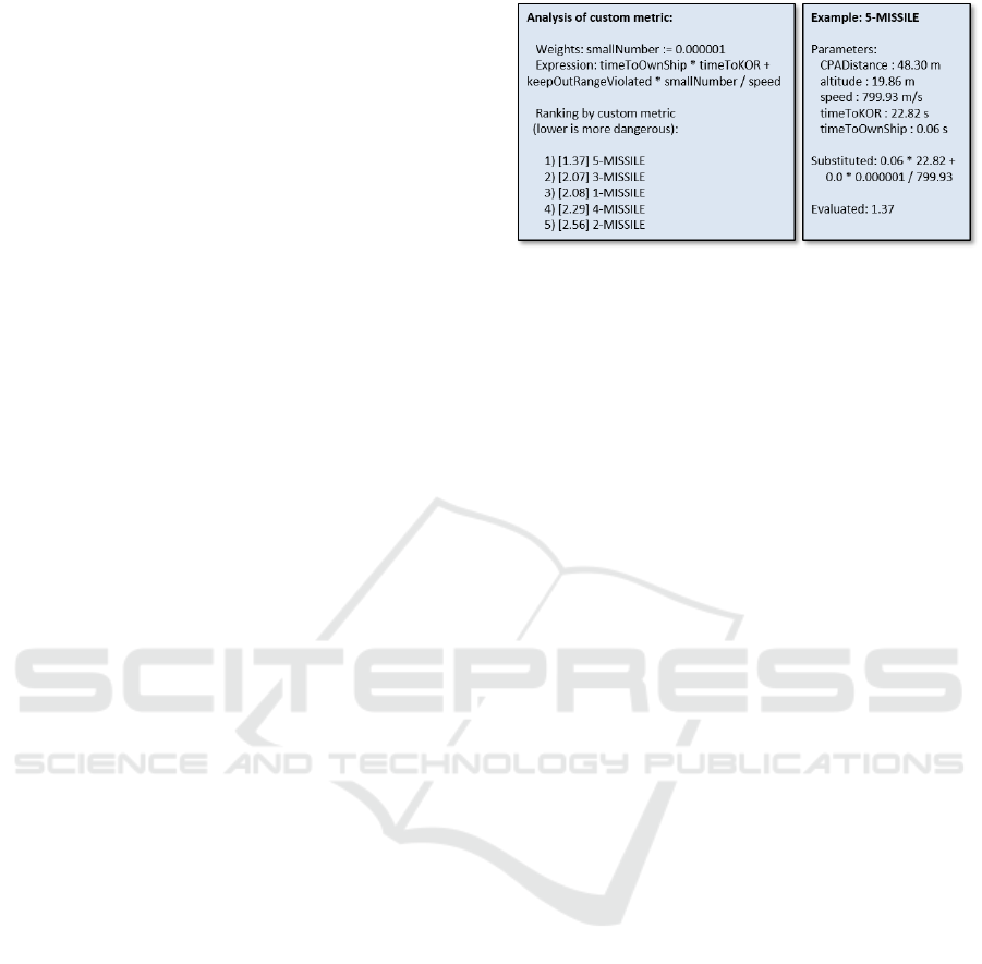
3. An analysis tool was also implemented in a gener-
ator that immediately produces a report providing
visibility on the results provided by custom met-
rics, previously introduced in Section 4.2, with-
out having to run the simulator. The generated
report is based on a single given list of threats
to be ordered. Realistic lists of threats are easily
obtained by recording inputs to the Threat Rank-
ing components during simulation of threat sce-
narios. The report, shown in Figure 5, shows how
the custom tiebreaker metric is computed for each
threat. This immediately shows the user an exam-
ple outcome when applying the metric and gives
insight into what caused that outcome. For exam-
ple, it could show that a particular parameter is
typically dominating the metric and that weights
should be adjusted to make the metric achieve the
desired goal. This is particularly helpful when ex-
perimenting with complex custom metrics.
6.4 Relating Results to Versions of
Models and Tools (Pain 14)
In the broader picture of a code base and tools that
evolve over time, results of a simulation or an exe-
cution do not only depend on the inputs, such as the
scenario and own ship configuration, but also on the
Figure 5: Generated analysis showing result of applying a
custom metric to a particular set of threats.
source code revision and the version of simulators and
other tools. This is problematic if questions ever arise
over how a particular result was obtained. To be able
to trace and reproduce results, it is important to keep
track of which versions of what tools and source code
were used to create them. This also means that pre-
viously used versions of tools must be archived after
update in case they need to be used again.
To address this issue with the high-level simula-
tion environment, we keep the source code of the
simulator, the DSL grammars, instances of the lan-
guage, and the scenario under version management
using Subversion. Once results of a simulation are
created, the revision of source code of the generator is
stored in an accompanying file. This file also contains
the version numbers of the simulator and other rele-
vant tools. The file is stored together with the used
ship configuration file and Threat Ranking DSL in-
stance. Each generated artifact is furthermore anno-
tated with the version of the generator that created it to
improve traceability and debugging. Together, these
pieces of information ensure that each deterministic
simulation can be reproduced and that there is a clear
link between results and the set up that was used to
create them. Similar measures need to be taken for
the production platform and any other environments
that are used, but this is left as future work.
6.5 Quality of Generated Code (Pain 12)
Section 6.3 previously mentioned how we ensure
model quality. This section considers the quality
of generated code, which relates to quality of mod-
els, since our simulation models are code in either a
general-purpose programming language or in an exe-
cutable modeling language. To clearly distinguish the
scope of these two pains, Section 6.3 considers en-
suring quality at the level of DSL instances, before
any generation, and this discusses the quality of gen-
erated artifacts, such as simulation models or produc-
tion code.
As previously mentioned in Section 4.3, generated
MOMA3N 2018 - Special Session on Model Management And Analytics
760

simulation models and production code should always
produce the same ranking, given the same input. An
important issue is hence how to validate that this is
really the case. The challenge is that the models and
code execute in different environments that use differ-
ent languages and model some system components at
different levels of abstraction. As a result, even if the
exact same Threat Ranking algorithm is used in all
environments, the inputs of the Threat Ranking com-
ponent are not expected to be the same. For example,
a threat may be detected slightly earlier or later, im-
pacting the set of threats to rank at a particular point in
time, which in turn affects the scheduled engagements
and the set of threats later in the scenario. For this rea-
son, it is not always possible to compare results across
environments and draw meaningful conclusions about
consistency of semantics between generators.
Our solution to mitigate this pain is to remove the
differences in environment and execute all implemen-
tations in a single framework. This is achieved by
wrapping the generated production code and run it
in one of the simulation environments as software-in-
the-loop, which ensures that all generated implemen-
tations have the same inputs and that all other com-
ponents are implemented identically. This in turn en-
ables us to establish the consistency in semantics of
the generators by extensive regression testing through
comparison of results, following the recommendation
in (Voelter, 2010). Over time, through extensive test-
ing and use, this approach builds confidence that the
different generators implement the same semantics of
the DSL and hence that the Threat Ranking compo-
nent works correctly.
In addition to component-level testing, we also
perform integration testing in the complete system
to verify that components communicate correctly and
that system-level results, such as when and where
threats are neutralized in a particular scenario for a
given DSL instance, are consistent across implemen-
tations and do not unexpectedly change during de-
velopment. Note that comparing results from multi-
ple implementations does not imply that any imple-
mentation is correct. However, following this ap-
proach, all implementations must provide the same
incorrect result in order for it to pass the test, which
is rather unlikely. To further increase confidence in
the results, different generators can be implemented
by independent developers based on a common spec-
ification, following requirements for certification of
software components in safety-critical avionics sys-
tems (RTCA, Inc., 2012).
Manual validation is tedious and time-consuming
labor. To reduce this effort, validation has been auto-
mated to make it possible to run all combinations (or
a chosen subset) of DSL instances and scenarios by
pushing a single button. As recommended in (Voelter,
2009), the DSL instances used for testing have been
designed in such a way that they exercise as many
constructs of the language as possible to improve cov-
erage.
Since we are preparing for a situation where the
DSL itself evolves over time, it is important that inte-
gration testing is always done with the latest versions
of the language and its generators. However, Xtext
does not support automatic generation of a command
line DSL parser and generator that can be used for
integration testing after each commit. As a contri-
bution of this work, we have defined a method for
automatic generation of such a tool that can be used
with any Xtext project to enable continuous integra-
tion. A description of this method and an example
project is available online
1
. To automate all aspects
of testing, we have set up a Jenkins Automation server
that checks out the latest version of the code after each
commit, builds the compiler and runs all tests. This
enables defects to be caught early, improving phase
containment of defects, and ensures that only the lat-
est changes must be reviewed and debugged.
6.6 No Continuity in the Development
Process (Pain 1)
When developing code and generators for the differ-
ent environments, we noted three types of differences:
1) architectural differences, e.g., in the high-level
simulation environment, the result of the tiebreaker
was only used to determine the order of threats with
the same threat level, while in the high-fidelity en-
vironment it is an integral part of a complete real-
world scenario, 2) differences in implementation, e.g.,
different coordinate systems to represent positions or
support for different threat types, 3) differences in ab-
straction, e.g., the high-fidelity simulation environ-
ment uses more advanced algorithms for track predic-
tion. These types of differences are hardly surprising
since different environments were designed by differ-
ent people at different times for different purposes.
The differences in the first two categories were all
minor and could be overcome by an adaptation layer
that integrates the generated code into the respective
environments. For differences in the last category, we
had to think carefully if any of the differences affected
the design of the language or the generators. In the
case of Threat Ranking, we found that the differences
in abstraction could be safely encapsulated in the re-
spective environment. For example, it does not mat-
1
https://github.com/basilfx/xtext-standalone-maven-
build
Pain-mitigation Techniques for Model-based Engineering using Domain-specific Languages
761

ter which type of track prediction is used to determine
threat properties, such as the closest point of approach
or the time to reach the own ship, as each environment
can do this with their respective algorithms, just like
before the introduction of DSLs. The generator only
assumes that there is a way to access these properties
in all environments, which was possible in our case.
Although we could bridge the differences and use
a single Threat Ranking model for different environ-
ments corresponding to different stages of design,
adapters and workarounds are not an ideal solution
in the long term. We recommend carefully aligning
concepts, architecture and implementation between
environments if model-based engineering should be
used as a continuous process in all stages of design.
Ideally, we recommend using a single framework, as
shown in Figure 6. The envisioned framework can be
used in all phases of development and allows a flex-
ible combination of abstract models, detailed mod-
els, code, and hardware. The upper layer in Figure 6
shows the generic infrastructure with three key com-
ponents: 1) the simulation framework, 2) a repository
of components, and 3) the reference architecture of
the product. In the bottom layer, this infrastructure is
used to develop a product.
This envisioned framework allows virtual proto-
types to be quickly assembled by re-using existing
models from the component repository and develop-
ing new models as necessary. The framework gener-
ates high-level simulation models of software (SW)
and hardware (HW) components from the selected
models, allowing the complete system to be simu-
lated. This enables the company to reach an agree-
ment on the ship configuration at an early stage of the
design process. The benefit of this is that it reduces
the specification phase of the system (and thereby de-
sign time) and reduces the risk of changes to the sys-
tem once the development has started.
Once a system has been specified, it is in-
crementally refined to use higher fidelity models
(SW+/HW+). The higher fidelity simulation mod-
els generated from these models provide increasingly
accurate performance metrics than in earlier phases,
although at the cost of longer development times of
new models and increased simulation times. These
simulations validate that the system that was defined
truly delivers the required performance. As the actual
software and hardware components are being devel-
oped, simulation models are gradually replaced us-
ing a software-in-the-loop and hardware-in-the-loop
approach, respectively, allowing incremental verifica-
tion of developed components before the entire sys-
tem is developed. Once all components are devel-
oped, they are deployed using a deployment frame-
work based on the reference architecture.
The main benefits of this model-based vision are
that it provides a continuous and incremental devel-
opment process with a high level of reuse between
systems and development phases. This addresses the
problems from Section 1 by: 1) reducing development
time by increasing productivity through re-use, im-
proved communication, lower defect rates, and better
phase-containment of defects, and 2) improves evolv-
ability by enabling changes to be made at model level
and allowing artifacts of the system to be regenerated.
7 OPEN ISSUES
After presenting the results of our investigation, this
section proceeds by defining a number of open issues
that arose during this work. These issues may serve
as suggestions for future research in this area.
1. Ensuring semantic consistency of generators
by construction. Currently, we manually imple-
ment the semantics of the DSL in each genera-
tor and validate their consistency by comparing
the outputs of the generated algorithms when test-
ing in a common environment. While this worked
reasonably well in our case, it means that each se-
mantic change needs to be implemented in each
generator. An interesting option could be to spec-
ify the semantics on an abstract level and generate
implementations that are consistent by construc-
tion. This would ensure that changes in semantics
would only be made in a single place, which could
be advantageous for highly evolvable systems.
2. Validation of implementations at different lev-
els of abstraction. In our case study, all im-
plementations are at the same level of abstrac-
tion. This allowed us to expect the same output
from all implementation given an identical envi-
ronment, which served as a base for our validation
approach. In the general case, simulation mod-
els in different frameworks and production code
will have different abstraction levels, which will
require a different validation method. A possible
solution may be to specify tolerances for differ-
ences between results, if these are known.
3. Techniques to develop a single simulation
framework that can be used throughout the de-
velopment chain. While the vision in Figure 6
seems like a promising way forward, it is not
clear how to technically realize it. Perhaps indus-
try standard frameworks for co-simulation, such
as High-level Architecture (HLA) (SISO, 2010),
could be an important building block to ensure in-
MOMA3N 2018 - Special Session on Model Management And Analytics
762

Figure 6: Vision of a single framework for all development phases.
teroperability between models at different levels
and implementations in hardware and software?
8 CONCLUSIONS
This paper discusses the first steps towards transfer-
ring an approach to Model-based engineering (MBE)
and domain-specific languages (DSLs) to a company
in the defense domain. The goal of this approach
is to reduce design-time and improve evolvability by
establishing continuity and reuse between different
stages of design, such as early design space explo-
ration, detailed performance estimation, and prod-
uct implementation. The approach achieves this
goal by using domain-specific models as the sole
truth to (re-)generate simulation models and product
code, thereby enabling quick changes while ensur-
ing mutual consistency. However, any new technol-
ogy comes with both pains and gains and this work
presents an investigation into the pains associated
with this approach and how they can be mitigated.
A list of 14 technical pains related to MBE rep-
resentative of our industrial partners is presented and
six selected pains are further discussed in the context
of industrial practice. A case study of a Threat Rank-
ing component in a Combat Management System is
then carried out to experience the selected pains and
propose techniques to mitigate or eliminate them. The
results of our investigation have convinced the com-
pany that the approach is feasible for simple compo-
nents, which has allowed us to continue the work with
a more complex case study. This will allow us to ad-
dress more of the specified pains, as well as the three
presented open issues.
REFERENCES
Baker, P., Loh, S., and Weil, F. (2005). Model-driven en-
gineering in a large industrial context - Motorola case
study. Model Driven Engineering Languages and Sys-
tems, pages 476–491.
Bettini, L. (2016). Implementing domain-specific languages
with Xtext and Xtend. Packt Publishing Ltd.
Beuche, D., Papajewski, H., and Schr
¨
oder-Preikschat, W.
(2004). Variability management with feature models.
Science of Computer Programming, 53(3):333–352.
Broy, M., Kirstan, S., Krcmar, H., Sch
¨
atz, B., and Zimmer-
mann, J. (2012). What is the benefit of a model-based
design of embedded software systems in the car in-
dustry? Emerging Technologies for the Evolution and
Maintenance of Software Models, pages 343–369.
Erdweg, S., Van Der Storm, T., Voelter, M., Tratt, L.,
Bosman, R., Cook, W. R., Gerritsen, A., Hulshout, A.,
Kelly, S., Loh, A., et al. (2015). Evaluating and com-
paring language workbenches: Existing results and
benchmarks for the future. Computer Languages, Sys-
tems & Structures, 44:24–47.
Goul
˜
ao, M., Amaral, V., and Mernik, M. (2016). Quality in
model-driven engineering: a tertiary study. Software
Quality Journal, 3(24):601–633.
Hutchinson, J., Whittle, J., and Rouncefield, M. (2014).
Model-driven engineering practices in industry: So-
cial, organizational and managerial factors that lead to
success or failure. Science of Computer Programming,
89:144–161.
International Organization for Standardization (2011). ISO-
IEC 25010: 2011 Systems and Software Engineering-
Systems and Software Quality Requirements and Eval-
uation (SQuaRE)-System and Software Quality Mod-
els. ISO.
Karsai, G., Krahn, H., Pinkernell, C., Rumpe, B.,
Schindler, M., and V
¨
olkel, S. (2014). Design guide-
lines for domain specific languages. arXiv preprint
arXiv:1409.2378.
Kurtev, I., Schuts, M., Hooman, J., and Swagerman, D.-J.
(2017). Integrating interface modeling and analysis in
an industrial setting. In MODELSWARD, pages 345–
352.
Melleg
˚
ard, N., Ferwerda, A., Lind, K., Heldal, R., and
Chaudron, M. R. (2016). Impact of introducing
Pain-mitigation Techniques for Model-based Engineering using Domain-specific Languages
763

domain-specific modelling in software maintenance:
An industrial case study. IEEE Transactions on Soft-
ware Engineering, 42(3):245–260.
Mernik, M., Heering, J., and Sloane, A. M. (2005). When
and how to develop domain-specific languages. ACM
computing surveys (CSUR), 37(4):316–344.
Mohagheghi, P. and Dehlen, V. (2008). Where is the
proof? – a review of experiences from applying
MDE in industry. Lecture Notes in Computer Science,
5095:432–443.
Mooij, A. J., Hooman, J., and Albers, R. (2013). Gaining
industrial confidence for the introduction of domain-
specific languages. In Computer Software and Appli-
cations Conference Workshops (COMPSACW), 2013
IEEE 37th Annual, pages 662–667. IEEE.
Mooij, A. J., Joy, M. M., Eggen, G., Janson, P., and
R
˘
adulescu, A. (2016). Industrial software rejuvena-
tion using open-source parsers. In International Con-
ference on Theory and Practice of Model Transforma-
tions, pages 157–172. Springer.
RTCA, Inc. (2012). RTCA/DO-178C. U.S. Dept. of Trans-
portation, Federal Aviation Administration.
SISO, S. (2010). IEEE Standard for Modeling and Simula-
tion (M&S) High Level Architecture (HLA)– Frame-
work and Rules. IEEE Std 1516-2010 (Revision of
IEEE Std 1516-2000), pages 1–38.
Smith, P. F., Prabhu, S. M., and Friedman, J. (2007). Best
practices for establishing a model-based design cul-
ture. Technical report, SAE Technical Paper.
Torchiano, M., Tomassetti, F., Ricca, F., Tiso, A., and Reg-
gio, G. (2013). Relevance, benefits, and problems of
software modelling and model driven techniques – a
survey in the Italian industry. Journal of Systems and
Software, 86(8):2110–2126.
Vetro, A., Bohm, W., and Torchiano, M. (2015). On the ben-
efits and barriers when adopting software modelling
and model driven techniques – an external, differen-
tiated replication. In Empirical Software Engineering
and Measurement (ESEM), 2015 ACM/IEEE Interna-
tional Symposium on, pages 1–4. IEEE.
Voelter, M. (2009). Best practices for DSLs and model-
driven development. Journal of Object Technology,
8(6):79–102.
Voelter, M. (2010). Architecture as language. IEEE Soft-
ware, 27(2):56–64.
Voelter, M. and Visser, E. (2011). Product line engineering
using domain-specific languages. In Software Product
Line Conference (SPLC), 15th International, pages
70–79. IEEE.
Whittle, J., Hutchinson, J., and Rouncefield, M. (2014). The
state of practice in model-driven engineering. IEEE
software, 31(3):79–85.
Wile, D. (2004). Lessons learned from real DSL experi-
ments. Sci. Comput. Program., 51(3):265–290.
MOMA3N 2018 - Special Session on Model Management And Analytics
764
