
Feature Extraction and Pattern Recognition from Fisheye Images in
the Spatial Domain
Konstantinos K. Delibasis
1
and Ilias Maglogiannis
2
1
Dept. of Computer Science and Biomedical Informatics, Univ. of Thessaly, Lamia, Greece
2
Dept. of Digital Systems, Univ. of Pireus, Greece
Keywords: Omni-directional, Fisheye Image, Feature Extraction, Spatial Domain.
Abstract: Feature extraction for pattern recognition is a very common task in image analysis and computer vision.
Most of the work has been reported for images / image sequences acquired by perspective cameras. This
paper discusses the algorithms for feature extraction and pattern recognition in images acquired by omni-
directional (fisheye) cameras. Work has been reported using operators in the frequency domain, which in
the case of fisheye/omnidirectional images involves spherical harmonics. In this paper we review the recent
literature, including relevant results from our team and state the position that features can be extracted from
spherical images, by modifying the existing operators in the spatial domain, without the need to correct the
image for distortions.
1 INTRODUCTION
The use of very wide field cameras is becoming very
wide in domains like security, robotics, involving
application such as silhouette segmentation, pose
and activity recognition, visual odometry, SLAM
and many more. Several types of cameras exist that
offer 180
o
field of view (FoV). These cameras are
often called spherical, fisheye, or also omni-
directional. The last term is also used for cameras
with FoV close to 360
0
, which may cause some
confusion. We will use the terms interchangeably for
the rest of the paper. A FoV of 180
0
or more, can be
achieved using dioptric systems (spherical lens), or a
combination of catadioptric (mirror, parabolic or
spherical) and dioptric (lens). The 360
0
deg FoV
omnidirectional cameras usually involve two mirrors
and at least one lens. Both types of images can be
treated in the same mathematic way, since in both
cases the resulting images are defined over spherical
coordinates (θ,φ) .
The use of this type of cameras is increasing in
robotic and in video surveillance applications, due to
the fact that they allow constant monitoring of all
directions with a single camera. The price to pay is
the very strong deformation induced by the camera,
which involves rapid deterioration of spatial resolu-
tion towards the periphery of the FoV. This deforma-
tion has been studied by researchers, using a number
of different image formation models. In principle,
straight lines are imaged as conic curves. Thus, the
images acquired by the fisheye camera are very diffe-
rent than the images acquired by perspective (proje-
ctive) cameras. This induces extra complexity for
image processing, as well as computer vision tasks.
In this work, we review some of the prominent
work on image processing, feature extraction and
pattern recognition from fisheye images and
describe our results on a number of relevant tasks,
using image processing techniques in the spatial
domain, exploiting the calibration of the camera.
More specifically, results are presented for: a)
redefining the Gaussian kernel in the spatial domain,
without distortion correction, b) redefining Zernike
moment invariants for calibrated fisheye images and
applying them for human pose recognition, c)
employing the camera calibration for human
silhouette refinement, labelling and tracking and
finally, d) using the main principles of image
formation to detect human fall events using a single
fisheye camera, without requiring exact calibration.
These results enhance our position that efficient
image processing and computer vision techniques
can be achieved in the case of 180 deg FoV images,
directly on the spatial image domain, without the
need to employ spherical Fourier Transform, or
perform distortion correction, or remap the image to
different grid.
460
Delibasis, K. and Maglogiannis, I.
Feature Extraction and Pattern Recognition from Fisheye Images in the Spatial Domain.
DOI: 10.5220/0006658704600465
In Proceedings of the 13th International Joint Conference on Computer Vision, Imaging and Computer Graphics Theory and Applications (VISIGRAPP 2018) - Volume 4: VISAPP, pages
460-465
ISBN: 978-989-758-290-5
Copyright © 2018 by SCITEPRESS – Science and Technology Publications, Lda. All rights reserved
2 METHODOLOGY
2.1 Fisheye Camera Calibration
Almost all the methods dealing with spherical
images, assume a correspondence between image
pixels and direction of view in the real world,
preferably using the spherical coordinates (azimuth θ
and elevation φ). This task is achieved by camera
calibration. Image formation for fisheye is quite
different than the simple projective (pinhole)
camera. Several models for fisheye image formation
have been proposed. In (Li H. and Hartley) and
(Shah and Aggarwal 1996) the calibration of fisheye
camera is reported using high degree polynomials to
emulate the strong deformation introduced by the
fisheye lens, radial and/or tangential. We have
proposed a fisheye camera calibration (Delibasis,
Plagianakos, and Maglogiannis 2014) that exploits
the spherical reflection – central projection model,
proposed by (Geyer and Daniilidis, 2001).
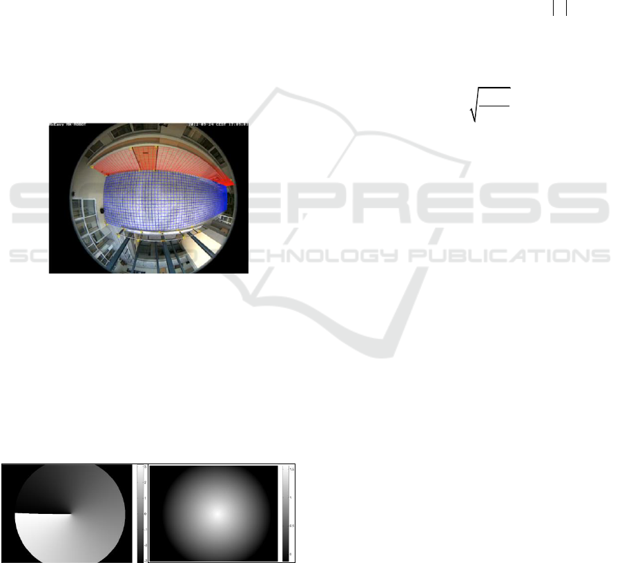
Figure 1: The achieved fisheye calibration, by reprojecting
the floor and a wall, from (Delibasis, Plagianakos, and
Maglogiannis 2014).
Further, we describe the inverse fish-eye camera
model, i.e. obtaining the direction of view for any
pixel (j,i) in the video frame, by defining two angles:
the azimuth θ and the elevation φ. These angles are
precalculated for every pixel of the frame and stored
in a look-up table to accelerate dependent image
processing tasks (Fig. 2).
Figure 2: The azimuth and elevation for a fisheye image,
from (Delibasis, Plagianakos, and Maglogiannis 2014).
2.2 Feature Extraction from Spherical
Images
In (Hansen, Corke, Boles, Wageeh and Daniilidis,
2007), the well-known Scale-Invariant Feature
Transform SIFT image descriptors that were intro-
duced in (Lowe) are redefined for omnidirectional
images. The implementation is performed in the
frequency domain. However, since the image forma-
tion model uses spherical optical element and central
projection, the omnidirectional image is defined over
the space of spherical coordinates (azimuth θ and
elevation φ). Thus, the image can be decomposed as
a weighted sum of spherical harmonic functions
,
m
l
Y
of degree l and order m, with
ml
. This
decomposition is often called Spherical Fourier
Transform (SFT). The Gaussian kernel has been
defined in the (θ,φ) image domain using spherical
harmonics of the 0
th
order (T. Bulow 2004)
1
0
21
, ; ,
4
l l kt
l
l
l
G t Y e
(1)
The Gaussian kernel may be projected on the
omni-directional image, as shown in Fig. 1 of
(Hansen, Corke, Boles, Wageeh and Daniilidis,
2007). However, in that work, the convolution of an
image defined in the (θ,φ) space is defined in the
frequency domain, using the SFT, rather than in the
(θ,φ) space.
The work of (Cruz-Mota et al 2012) also
employs the use of SFT to detect points of interest
using the well-known SIFT. It is very interesting that
the authors state “we need to pass through the
spherical
Fourier domain because convolution on the
sphere in spatial domain (3D) is hard (almost
impossible) to compute”
Others have reported exploiting the image space,
rather than the frequency domain, for specific
kernels. In (Andreasson, Treptow, and Duckett,
(2005)), the authors also used a simplified version of
SIFT feature extraction method (eg. no multireso-
lution was used) for robot navigation by fisheye
camera, obtaining good results, however there is no
mention if the approach is optimal with respect to
(Cruz-Mota et al 2012). In (Zhao, Feng, Wan, and
Zhang, (2015)), features are extracted from 360 FoV
omnidirectional images in the spatial domain, but
after the image has been mapped to a hexagonal
grid. In (Hara, Inoue, and Urahama, (2015)), 4-
neighbours and 8-neighbours Laplacian operators
have been proposed for omnidirectional panoramic
images.
Feature Extraction and Pattern Recognition from Fisheye Images in the Spatial Domain
461
2.2.1 Geodesic Distance Metric between
Pixels of the Calibrated Fish-eye Image
The formation of 180 FoV omni-directional image
using a spherical lens can be summarized as
following: the intersection of the line connecting the
real world point with the center of the optical
element is calculated with the optical element. This
intersection is then projected centrally on the image
sensor plane. It has been shown (Geyer and
Daniilidis (2001)) that by choosing the center of
projection, one can simulate the use of any quadratic
shape mirror (spherical, ellipsoid, paraboloid and
hyperboloid). This type of image formation induces
non-linear transformation of distances between
pixels.
In (Delibasis et al. 2016) we proposed the
definition of geodesic distance between pixels, to
replace the Euclidean distance, normally used for
projective cameras. More specifically, since the
geodesic curve of a sphere is a great circle, the
distance between any two points on a sphere is the
length of the arc, defined by the two points and
belonging to the great circle that passes through the
two points. The great circle has the same centre and
radius with the sphere. Let v
0
and v
1
be the position
vectors pointing to the unit sphere points P
0
and P
1
.
These points correspond to two pixels of the fisheye
image. The distance of these two pixels is defined as
the distance d of points P
0
and P
1
on the unit sphere
and can be easily calculated as the arc-length
between P
0
and P
1
:
0 1 0 0 0 0 0
1 1 1 1 1
cos cos ,sin cos ,sin
cos cos ,sin cos ,sin
vv
(2)
1
01
cosd
vv
(3)
2.2.2 Definition of the Gaussian Kernel for
Calibrated Fisheye Images
This distance metric can be applied to redefine the
Gaussian kernel, by replacing the Euclidean distance
in the exponent. Thus, a gaussian centered at pixel
0 0 0
,xyp
can be written as
2
0
2
,
2
2
1
, ; ;
2
g
d
g
g x y g e
pp
p
(4)
These concepts are visualized in Figure 3, where the
semi-spherical optical element of unit radius and the
image plane is displayed. The center of projection is
placed at –f on the Y axis, with f set to 0.2 (a value
obtained by the calibration of the actual Q24
Mobotix camera used in this work). The image plane
is tessellated into 128 equidistant points to resemble
the image pixels. 13 of these “pixels” (red dots in
Fig.3a) are backprojected on the spherical optical
element (both shown in different color). It is self-
evident that the back-projected points are no longer
equidistant.
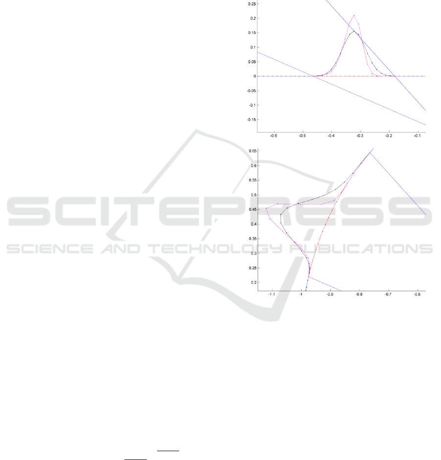
Figure 3: The Gaussian kernels generated using
traditional/ planar and geodesic pixel distance (black and
red curves respectively). The curves are placed (a) on the
spherical lens and (b) on the image plane.
The definition of a Gaussian within the 13-pixel
window, using the Euclidean distance between
pixels on the image plane is visualized as the black
curve in Fig. 3(a). If this Gaussian is back-projected
on the spherical optical element, the kernel depicted
in black at the periphery) is produced Fig. 3(a). As
expected, it is substantially different from a
Gaussian kernel, due to distance metric. In order to
generate a Gaussian kernel defined on the image
sensor, which is symmetric when applied on the
spherical lens, we have to modify the distance metric
between pixels on the sensor, according to the
geodesic distance of their back-projection on the
spherical lens.
VISAPP 2018 - International Conference on Computer Vision Theory and Applications
462
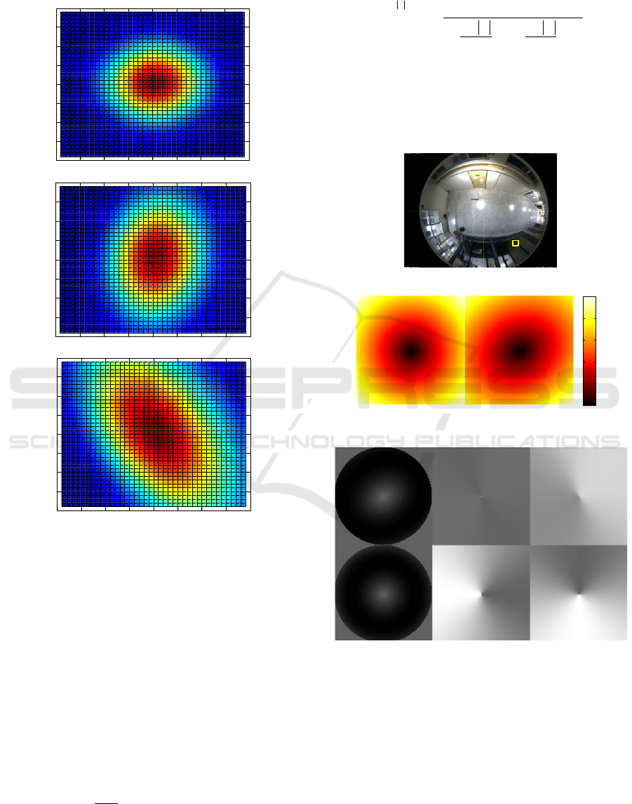
2D Gaussian kernels, produced as above are shown
in Fig. (4), at the center, and towards the periphery
of the fisheye image.
Figure 4: 2D Gaussian kernels, produced at the center
(top) and towards the periphery of the fisheye image
(bottom).
2.2.3 Definition of Zernike Moments in
Calibrated Fish-Eye Image
Zernike moment invariants (ZMI) have been used
regularly for pattern recognition in images and video
sequences. The calculation of Zernike moments
requires the distance and orientation with respect to
the centre of the image patch, for each pixel of the
segmented object / pattern to be classified. If the
geodesic distance between pixels is used, then the
ZMI can be calculated for the specific (calibrated)
fisheye image.
1
,,
nm nm
xy
n
Z f r V r
(6)
where
,
jm
nm nm
V r R r e
, r, θ are functions of
(x,y).
/2
2
0
!
1
! ! !
22
nm
s
ns
nm
s
ns
R r r
n m n m
s s s
..(7)
The substantial difference between traditional and
geodesically corrected ZMI for a calibrated fisheye
image is shown in Figure 5. The position of the
application of the ZMI is indicated in Figure 5(a) by
a yellow square.
(a) Fisheye image
(b) Traditional (left) and corrected (right) pixel distance
metric
(c) The resulting Zernike radial polynomial and angular
terms
Figure 5: Differences in the planar (left) and geodetic
definition (right) of (b) distance and (c) angle between two
image pixels, from (Delibasis et al. 2016).
2.2.4 Silhouette Segmentation in Calibrated
Fish-Eye Image
In (Delibasis et al. 2014) a refinement for the
segmentation of human silhouettes was proposed,
0 5 10 15 20 25 30 35 40
0
5
10
15
20
25
30
35
40
0 5 10 15 20 25 30 35 40
0
5
10
15
20
25
30
35
40
0 5 10 15 20 25 30 35 40
0
5
10
15
20
25
30
35
40
0
0.2
0.4
0.6
0.8
1
Feature Extraction and Pattern Recognition from Fisheye Images in the Spatial Domain
463
using spatial relations of the binary objects/parts of a
segmented silhouette, using clues from the
calibration of the fisheye camera. Results showed
that the method was quite robust, as well as
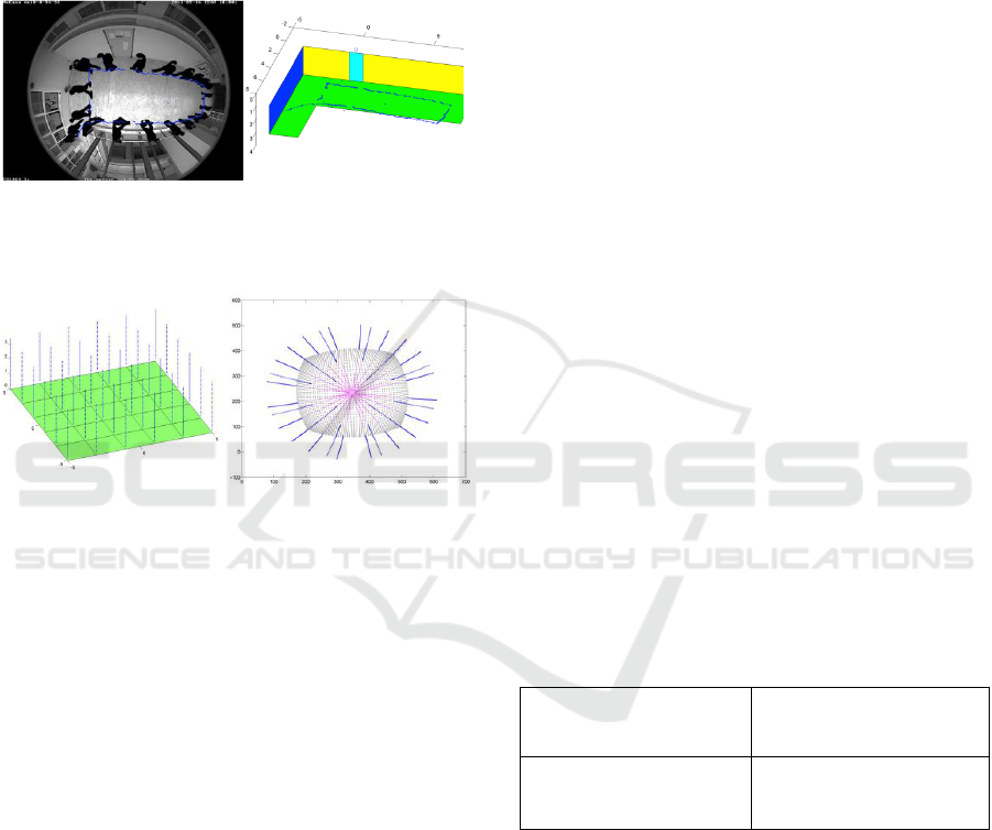
computationally efficient. Figure 6 shows a
composite frame with segmented silhouettes (a), as
well as the estimated trajectory in real world
coordinates (b).
(a)
(b)
Figure 6: Silhouette segmentation and tracking through a
fisheye camera, from (Delibasis et al. 2014).
Figure 7: Real world vertical lines and their rendering
through a fisheye camera with vertical optical axis, from
(Delibasis et al. 2015).
2.2.5 Fall Detection by Uncalibrated
Fish-eye Camera
In (Delibasis, and Maglogiannis, (2015)) a simple
and effective algorithm was proposed to detect
falling events of humans monitored by fisheye
camera. Instead of the full calibration of the camera,
the only requirement was that the camera axis
should point parallel to the vertical axis. The
proposed algorithm exploits the model of image
formation to derive the orientation in the image of
elongated vertical structures. World lines are imaged
as parts of curves, which, if extrapolated
(equivalently extending the 3D vertical lines to
infinity), will all intersect at the center of the
camera’s field of view (FoV). Lines parallel to the
optical axis are rendered as straight lines. Line
extrapolation is shown in dotted style (Figure 7).
The floor is drawn as it would appear at z=3.5
meters from the ceiling where the camera is
installed.
The proposed fall detection algorithm consists of
the following simple steps:
1. The center of the FoV is detected (offline, for a
single video frame).
2. For each video frame:
2.1. The silhouette is segmented
2.2. Its major axis is calculated
2.3. If the silhouette is sufficiently elongated
and its major axis does not point close to
the center of FoV, then the silhouette is
assumed to correspond to a falling person
3 RESULTS
The proposed geometry-based silhouette refinement
algorithm was applied to 5 video sequences. Two
classes of pixels were considered: pixels that belong
to human silhouettes inside the room (excluding any
other activity) and the rest of the pixels. Table 1
shows the confusion matrix for the segmentation of
the, with and without the application of the proposed
algorithm – (1
st
row true positive -TP, false negative
pixels -FN, 2
nd
row: false positive -FP, true negative
pixels -TN). It can be observed that the number of
TP and FN pixels remain almost the same with and
without the application of the geometry-based
refinement. The number of FP pixels decreases
significantly, whereas TN increases with the
application of the proposed algorithm.
Table 1: The confusion matrix of the human silhouette
segmentation for 5 videos, with and without the
application of the proposed geometry-based algorithm
from (Delibasis et al. 2014).
Segmentation only
Segmentation and
geometry-based silhouette
refinement
172388
21828
142676
48815108
172109
22085
23725
48934081
In (Delibasis, et al. 2016), the Zernike Moment
Invariants (ZMI) for the calibrated fisheye image
were tested against the traditional ZMI in a problem
of pose recognition. Synthetic video frames were
used for training and testing. Testing was performed
on real video frames, as well. The achieved results
for synthetic data (5 different poses) are shown in
Table 2. The superiority of the proposed ZMI, is
evident, although marginal. More experimentation
can be found in (Delibasis, et al. 2016), which
validates these findings.
VISAPP 2018 - International Conference on Computer Vision Theory and Applications
464

Table 2: The classification accuracy of the segmented
silhouette pose for different orders of the traditional radial
Zernike implementation (Delibasis, et al. 2016).
Zernike
Degree n,
Order m
Geodesic
correction
Classification
Accuracy (%)
Video 1
Video 2
n = 2,4,6,8,10,
m=0
NO
93.39
94.53
YES
94.09
96.13
n = 2,4,6,8,…,20,
m=0
NO
91.68
94.14
YES
94.24
95.94
n = 2,4,6,8,…,30,
m=0
NO
92.11
94.01
YES
92.24
95.75
The proposed algorithm for fall detection has
been applied to two video sequences containing 5
fall events, acquired by the fish-eye camera at 15 fps
frame rate of 480x640 pixels. The confusion matrix
for both videos is shown in Table 3.
Table 3: Confusion matrix for fall classification, from
(Delibasis and Maglogiannis, 2015).
Standing
Not
Standing
Undefined
Standing
1374
256
388
Not
Standing
513
1684
4 CONCLUSIONS
A number of image processing and computer vision
tasks have been presented, applied to images and
videos acquired by a calibrated fisheye camera. First
we defined a metric for pixel distances, based on the
image formation model. Subsequently we applied
this metric to the definition of the Gaussian kernel,
as well as to the re-definition of Zernike Moment
Invariants (ZMI). The corrected ZMI outperformed
the traditional ones for pose recognition. Two more
applications, involving silhouette segmentation and
fall detection, the later one without the requirement
for full fisheye calibration were reviewed. All these
fisheye-specific processing tasks were applied to
spatial domain, without the need to remap the image
to different grids, or correct for the strong
distortions. These results support our position, that
efficient image processing and analysis algorithms
can be performed directly in the fish-eye image
domain. Further work includes the application of a
number of other feature extraction algorithms, such
as SIFT, Harris corner detection and Hough
Transform.
REFERENCES
Hansen, P., Corke P., Boles W. and Daniilidis, K. (2007)
Scale Invariant Feature Matching with Wide Angle
Images. In Proceedings IEEE/RSJ International
Conference on Intelligent Robots and Systems, pages
pp. 1689-1694, San Diego, USA.
Lowe D., “Distinctive image features from scale-invariant
keypoints,” International Journal of Computer Vision,
vol. 60, no. 2, pp. 91–110, 2004.
Bulow,T., “Spherical diffusion for 3D surface smoothing,”
IEEE Transactions on Pattern Analysis and Machine
Intelligence, vol. 26, no. 12, pp. 1650–1654, Dec
2004.
Hara, K., Inoue, K., and Urahama, K. (2015). Gradient
operators for feature extraction from omnidirectional
panoramic images. Pattern Recognition Letters, 54,
89-96.
Cruz-Mota, J., Bogdanova, I., Paquier, B., Bierlaire, M.,
and Thiran, J. P. (2012). Scale invariant feature
transform on the sphere: Theory and applications.
International journal of computer vision, 98(2), 217-
241.
Andreasson, H., Treptow, A., and Duckett, T. (2005).
Localization for mobile robots using panoramic vision,
local features and particle filter. In Robotics and
Automation, 2005. ICRA 2005. Proc. of the 2005 IEEE
International Conference on (pp. 3348-3353).
Zhao, Q., Feng, W., Wan, L., and Zhang, J. (2015).
SPHORB: a fast and robust binary feature on the
sphere. International Journal of Computer Vision,
113(2), 143-159.
Li H. and Hartley R., Plane-Based Calibration and Auto-
calibration of a Fish-Eye Camera, in P.J. Narayanan et
al. (Eds.): ACCV 2006, LNCS 3851, pp. 21–30, 2006,
Springer-Verlag Berlin Heidelberg 2006.
Shah S. and Aggarwal J. 1996, Intrinsic parameter calibre-
tion procedure for a high distortion fish-eye lens
camera with distortion model and accuracy estimation,
Pattern Recognition, 29(11), 1775- 1788, 1996.
Delibasis, K. K., Plagianakos, V. P. and Maglogiannis, I.
“Refinement of human silhouette segmentation in
omni-directional indoor videos,” Computer Vision and
Image Understanding, vol. 128, pp. 65-83, 2014.
Delibasis, K. K., S. V. Georgakopoulos, K. Kottari, V. P.
Plagianakos, and I. Maglogiannis. (2016)
"Geodesically-corrected Zernike descriptors for pose
recognition in omni-directional images." Integrated
Computer-Aided Engineering, Preprint (2016): 1-15.
Geyer, C., and Daniilidis, K. (2001). Catadioptric
projective geometry. International journal of
computer vision, 45(3), 223-243.
Delibasis, K. K., and Maglogiannis, I. (2015). A fall
detection algorithm for indoor video sequences
captured by fish-eye camera. In Bioinformatics and
Bioengineering (BIBE), 2015 IEEE 15th International
Conference on (pp. 1-5).
Feature Extraction and Pattern Recognition from Fisheye Images in the Spatial Domain
465
