
Prototyping and Evaluating Sensory Substitution Devices by Spatial
Immersion in Virtual Environments
Aziliz Guezou-Philippe
1
, Sylvain Huet
1
, Denis Pellerin
1
and Christian Graff
2
1
Univ. Grenoble Alpes, CNRS, Grenoble Institute of Engineering, GIPSA-lab, 38000 Grenoble, France
2
Univ. Grenoble Alpes, Univ. Savoie Mont Blanc, CNRS, LPNC, 38000 Grenoble, France
Keywords:
Sensory Substitution, Virtual Environments, Motion Capture, Pointing Device, Eye Tracking.
Abstract:
Various audio-vision Sensory Substitution Devices (SSDs) are in development to assist people without sight.
They all convert optical information extracted from a camera, into sound parameters but are evaluated for
different tasks in different contexts. The use of 3D environments is proposed here to compare the advantages
and disadvantages of not only software (transcoding) solutions but also of hardware (component) specifics,
in various situations and activities. By use of a motion capture system, the whole person, not just a guided
avatar, was immersed in virtual places that were modelled and that could be replicated at will. We evaluated
the ability to hear depth for various tasks: detecting and locating an open window, moving and crossing an
open door. Participants directed the modelled depth-camera with a real pointing device that was either held
in the hand or fastened on the head. Mixed effects on response delays were analyzed with a linear model to
highlight the respective importance of the pointing device, the target specifics and the individual participants.
Results are encouraging to further exploit our prototyping set-up and test many solutions by implementing
e.g., environments, sensor devices, transcoding rules, and pointing devices including the use of an eye-tracker.
1 INTRODUCTION
1.1 Sensory Substitution
Sensory substitution consists in replacing an impaired
sensory channel by another, functional, one. Most
Sensory Substitution Devices (SSD) are used to com-
pensate visual impairments by the auditory or tactile
senses. They aim at assisting in different kinds of
tasks like object finding and navigating (Stoll et al.,
2015). Electronic SSDs rely on (fig. 1):
• a sensor such as a color camera or a depth camera
(e.g. Kinect). It is fastened on the user or freely
positionable by him/her,
• a transcoder which processes the information
coming from the sensor to drive an actuator,
• an actuator which stimulates a functional sense of
the user, for example hearing or touch.
Environment Sensor Transcoder Actuator
X3333X
The3user3positions
the3sensor
Figure 1: Electronic sensory substitution device principle.
Bach-y-Rita et al. carried out a pioneering work
highlighting the importance of the action perception
loop in these systems (Bach-Y-Rita et al., 1969). They
showed that their Tactile Vision Substitution System
(TVSS) which converts an image captured by a video
camera into tactile stimuli, was much more efficient
when users directed the video sensor themselves. In-
deed, actions regulate perception and perception con-
stantly directs actions. Therefore, it is essential for the
user to be able to position the sensor (fig. 1) or a focal
point in the scene. The efficiency of the scene point-
ing technique, e.g. by hand or with the head appears
as an important issue.
The reader can refer to (Kristj
´
ansson et al., 2016)
for a state of the art on SSD.
596
Guezou-Philippe, A., Huet, S., Pellerin, D. and Graff, C.
Prototyping and Evaluating Sensory Substitution Devices by Spatial Immersion in Virtual Environments.
DOI: 10.5220/0006637705960602
In Proceedings of the 13th International Joint Conference on Computer Vision, Imaging and Computer Graphics Theory and Applications (VISIGRAPP 2018) - Volume 4: VISAPP, pages
596-602
ISBN: 978-989-758-290-5
Copyright © 2018 by SCITEPRESS – Science and Technology Publications, Lda. All rights reserved
1.2 Problematic
Evaluation or appropriation of an SSD in the real
world raises the following problems:
1. it can only be done after a complete prototype has
been built, which may be long and tedious,
2. the scene to immerse the user may be either
a complex natural scene which makes difficult
the adjustment and evaluation of the transcoding
laws, or a simplified real laboratory scene specif-
ically constructed for the tests which is always
time-consuming to set up and hard to replicate.
To address some of these problems, recent works
have been based on moving an avatar in a 3D virtual
environment. These avatars are steered using a video
game controller with a tactile feedback (Khoo et al.,
2012), the Phantom device with haptic and sonic feed-
backs (Lahav et al., 2015), or keyboard keys (Maid-
enbaum et al., 2016) with sonic feedback generated
with the EyeMusic SSD (Abboud et al., 2014). These
works highlight the benefits of using 3D virtual envi-
ronments to test and to practice on SSD. However, in
such set-ups, the user’s sensory feedbacks are limited
to those generated according to the positioning of the
avatar.
We constructed an experimental set-up model
(section 2) in order to get closer to real-life sensory
and motor experience than through an avatar. We used
a motion capture system to immerses the whole user’s
body in the virtual 3D environment that s/he perceives
through a SSD. This situation was closer to an ecolog-
ical context as it preserved most of the natural action
perception loops.
Thus our set-up model aimed at combining both
the agility advantages of virtual worlds that can be
designed, changed and replicated at will for situations
and tasks, and incarnation in the real-world where the
human body can experience natural sensations and
gestures. We tested it on blind-folded users (sec-
tion 3). It allowed to compare performances in object
search and navigation tasks depending on two point-
ing techniques: by moving one’s hand or one’s head.
We also adapted the setup to a more original way
of manipulating the sensor device (section 4), based
on (blind) gaze movements. Although it has not
been tested on a significant sample of participants, it
showed operational enough to be presented as another
example of adaptability of the prototyping /evaluation
set-up model and opens up on large perspectives.
2 CONNECTING SSD INTO A
VIRTUAL ENVIRONMENT
2.1 Principle
While the general principle of SSD (fig. 1) remains
the same, the real world environment and the hard-
ware sensor are both replaced by a virtual scene and a
virtual camera controled by the user (fig. 2).
!"#$%&'()*+
,"#-*.)*$
!"#$%&'
/)*/-#
0#&*/1-2)# 31$%&$-#
04)(%/)#(5-/"$"-*/
&(5-"*$)#
6-"*$)#(5-/"$"-*
&*2(-#")*$&$"-*
7-$"-*(
1&5$%#)
8&9
8:9
819
8)9
;
/
<
/
=
/
829
;
/
<
/
=
/
3D#modelling
Targeted SSD
VRPN
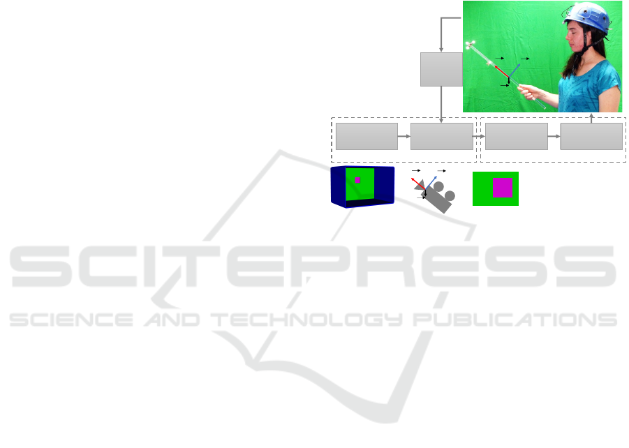
Figure 2: Designed experimental set-up principle.
(a) real stick equipped with 4 markers reflecting IR light
(b) real stick position and orientation
(c) virtual environment example
(d) virtual sensor positioned and oriented as the real stick
(e) image produced by the virtual sensor
Modeling the Virtual Environment. We used a 3D
modelling library to describe the environment. fig.
2(c) shows a virtual environment example: a wall in a
room is pierced by a square window.
Virtual Environment Capture. The virtual environ-
ment is captured by a virtual sensor, the scene camera,
as shown in fig. 2(d).
Matching Real and Virtual. To realize the immer-
sion, i.e. to link the real and virtual spaces, the user
must be able to manipulate the virtual sensor from the
real world. We used a motion capture system to ex-
tract a real object’s (fig. 2(a)) position and orientation
(fig. 2(b)). This position and orientation are repli-
cated on the virtual sensor (fig. 2(d)).
Interfacing with the Transcoder. To generate a per-
ceptual feedback of the virtual scene through the tar-
geted SSD, we extracted information from the virtual
sensor compatible with its transcoder. As an example,
fig. 2(e) represents the colour image acquired from
the viewpoint of the virtual sensor. This portion of
the background wall with the window is sent to the
transcoder of a SSD working on colour images.
The following subsections detail the technical so-
lutions we used to implement this principle.
Prototyping and Evaluating Sensory Substitution Devices by Spatial Immersion in Virtual Environments
597

2.2 Motion Capture
To acquire the position and the orientation of objects
(sensors) in space and interact with a virtual world,
we used a VICON motion capture system. Based on
a passive optical technology, it consists of a set of 12
infra-red T40s cameras, distributed around the vol-
ume to capture. Around each camera’s lens, a circular
array of infra-red projectors is placed to illuminate the
scene, and especially 8-mm spherical reflecting mark-
ers that were fixed on the objects to track. The images
captured by the infra-red cameras reveal the position
of the markers reflecting the infra-red from different
view angles. Based on a prior calibration, the posi-
tion of each marker is calculated by a triangulation-
type algorithm. From the relative position of markers
placed on a solid object, the VICON system delivers
its position and orientation in space, in a user-defined
referential. Fig. 2(a) shows the 4 markers placed
on the stick. Our room allowed the user to move in
a WxLxH=3x3x2m real volume. As we will see in
section 3 this is enough to carry out experiments on
mobility. However, the virtual environment can be
extended beyond this limit, even if the user cannot
physically visit it. The spatial accuracy of the VICON
system we used is in the order of a millimetre, and its
operating frequency is 515 Hz.
2.3 3D Modelling
A 3D modelling library or a 3D video game engine
is required to design a 3D virtual environment, for
immersing the user. We chose the OpenSceneGraph
(OSG) 3D library because it is free, cross-platform
and C++ programmable. Moreover it can be easily
interfaced with the VICON system. Its low-level na-
ture allows us to create simple scenes quickly. The
realistic aspect of the scenes is not a priority for our
experiments. If more realism were needed, a video
game engine such as Unity 3D could have been used.
2.4 Interfacing the Motion Capture
System and the 3D Modelling
The VICON Tracker software thus provides the spa-
tial configuration of the markers of objects to track
and it calibrates the system, and it also behaves
as a Virtual-Reality Peripheral Network (VRPN)
server. VRPN is a broadly-used device and network-
independent protocol for retrieving information from
virtual reality peripherals, such as motion capture sys-
tems or joysticks. By using a VRPN client, a sim-
ple program can obtain the position and orientation of
an object quite easily from the VICON system. The
client just has to indicate the name of the object to
track to the server.
We used the osgVRPN plugin to interface OSG
with the VICON system. osgVRPN behaves as a
VRPN client which positions and orients a scene cam-
era. For example, it allows to position and orient the
scene camera presented in fig. 2(d) according to the
position and orientation of the stick manipulated by
the user (fig. 2(a)).
2.5 Targeted SSD
SSDs transcoders use different kinds of inputs. For
example, some retrieve depth information from fo-
cused depth sensors (such as a laser beam), oth-
ers work on color images from standard cameras, or
depth maps from Kinect-like cameras. The following
subsection describes how to get these different types
of information from the OSG scene camera.
2.6 Interfacing the 3D Modelling with
the Targeted SSD
The OSG intersector mechanism can be used to re-
trieve focused depth information: it returns the list
of objects intersected by a ray coming from a given
pixel of the image captured by the scene camera. The
distance between each of these objects and the scene
camera is also given.
Thanks to callbacks on the rendering of the scene
camera, it is also possible to get back from the Graph-
ical Processing Unit (GPU) memory the color image
and the zbuffer corresponding to the camera’s point
of view. The zbuffer is used during graphic render-
ing to determine which triangles of the scene are vis-
ible from a given point of view. It can be considered
as a greyscale image whose levels represent the dis-
tance that separates the visible objects from the cam-
era. The zbuffer can be used as a depth map and thus
feed the SSDs transcoders using Kinect like sensors.
However, we would like to draw the reader’s atten-
tion on the fact that the zbuffer’s z
0
∈ [0; 1] values are
related to the actual distances z ∈ [z
n
;z
f
] (with z
n
the
distance to the nearest visible point, n for ”near” and
z
f
at the farthest visible point, f for ”far”) by equation
(1).
z
0
= A
1
z
+ B where A =
z
n
z
f
z
f
− z
n
and B =
z
f
z
f
− z
n
(1)
Thus, transformation on the zbuffer is necessary to
feed a transcoder waiting for a depth map in a given
distance unit, in millimetres for example.
VISAPP 2018 - International Conference on Computer Vision Theory and Applications
598
3 EXPERIMENTS
Human participants with normal vision were im-
mersed in a virtual environment they only perceived
through sound feedback comming from a SSD, for
two experiments. In the first one, participants used
the pointer to locate a virtual target while sitting on
a chair; in the second one, they used the pointer to
find an open door to walk from one virtual room to
another. The purpose of these experiments was to test
and compare two different pointing devices: a stick
held by the hand and a headset. To minimize response
variability due to training or strategy changes along
trials, participants learned to use the SSD with the
two pointing devices before starting the actual tests.
In this training phase lasting around 30 minutes, they
could open and close their eyes at will. During the
actual tests, partitioned into blocks of eight or six tri-
als, they kept their eyes closed. Participants had to
alternate pointer after each next block.
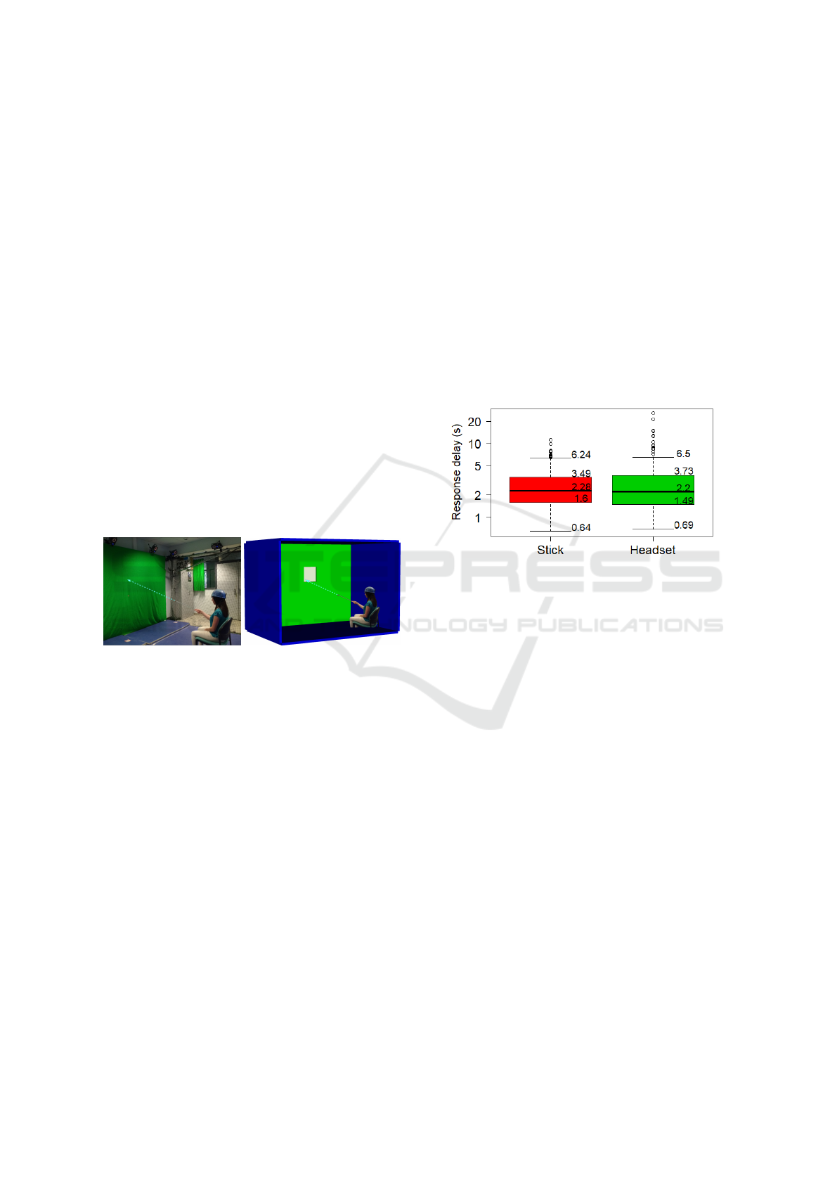
3.1 First Experiment: Detecting an
Open Window on a Virtual Wall
a) b)
Figure 3: First experiment a) participant in real environment
b) participant immersed in virtual environment.
The task was a partial replica of a real-world test used
as proof of concept for an original SSD (Twardon et
al. 2013). One woman and six men (Age: mean
= 21.8 years-old, SD = 0.4 ) were successfully im-
mersed in a virtual closed room (WxLxH=3x3x2m).
They sat 1.5m in front of a 3x2m wall. Their task
was to locate an open window on this wall (fig. 3).
The window could be in four different positions (top
right, top left, bottom right and bottom left quad-
rants), and two different sizes, large (75x75cm) or
small (50x50cm). The SSD delivered a 220Hz-sound
when the pointer was directed to the open window,
contrasting with the continuous 110Hz-sound emitted
when it was directed to the rest of the room (i.e. one
octave less). Tests were organized in eight blocks of
eight trials. Each block comprised the eight different
combinations of window position and size, randomly
ordered. At each trial, a starting signal was vocally
given to initiate the search. The participant told the
window position as soon as detected. The delay be-
tween starting signal and response was timed manu-
ally and measured in seconds.
Results. The pointing device seems not to affect the
delays (fig. 4). However the change of window’s
size and position may contribute to variability in the
measures, as well as individual differences between
participants and interactions between these variables.
To test these factors, a conventional ANOVA or a
Fisher test were discarded because repeated measures
were obtained from the same participants. In addi-
tion, a Shapiro test discarded normality within each
pointer devices’ sample. Therefore, a linear model
with mixed effects was preferred, with fixed variables
common to all participants, and individual partici-
pants’ effect as a random variable.
Figure 4: Distribution of the first experiment response delay
(in sec.) for all participants according to the pointer used
(red: stick, green: headset).
We used the lme4 package to perform our mixed
effect model analysis in R (Bates et al., 2015). The
model is defined as follows:
Y
pt,siz,pos,par
= µ + α
pt
+ β
siz
+ γ
pos
+ τ
par
+ ε
+I
2
(α
pt
,β
siz
,γ
pos
) + I
3
(α
pt
,β
siz
,γ
pos
)
(2)
with Y
pt,siz,pos,par
being the response delay (the log
transform of the delay in second), µ the mean de-
lay, α
pt
, β
siz
,γ
pos
the fixed effects respectively due
to the pointing device, the window’s size and the
window’s position, τ
par
the random effect due to
the individual participant, ε the error component
(or uncontrolled random effect) with ε → N(0,σ
2
1
),
and I
2
(α
pt
,β
siz
,γ
pos
), I
3
(α
pt
,β
siz
,γ
pos
) respectively
the 2
nd
and 3
rd
order interaction effect.
Following a parsimonious and simplified process,
the strongest p-value variable was successively with-
drawn from the model until the remaining p-value
variable is larger than 5%. The resulting model issued
from equation (2) was thus simplified as:
Y
pt,siz,pos,par
= µ + β
siz
+ γ
pos
+ τ
par
+ ε (3)
Thus, the response delay does not depend on the
pointer used. It strongly depends on the window’s
Prototyping and Evaluating Sensory Substitution Devices by Spatial Immersion in Virtual Environments
599
size and the participant. Window’s position also par-
ticipated to the response delay variability but to a
lesser extent. We used a multiple comparison test
(Hothorn et al., 2008) to study every effect signifi-
cance.
The multiple comparison test shows a very signifi-
cant effect of the window’s size (p = .0003 < 5%) on
the response delay, small window’s response delays
being longer than big window’s ones. Some window’s
positions shows slightly significant effects on the re-
sponse delay. Windows in position n
o
3 (at the bottom
left) are somewhat longer to find than those in posi-
tion n
o
1 and 2 (top right and top left with respectively
p = .0095 and p = .0072).
Conclusions. Results show that big windows are
faster to locate than small ones, with significant dif-
ferences between individual participants. By contrast,
the pointing devices can be considered as equivalent
in this task. However, directing the beam of the SSD
with the head may be uncomfortable when scanning
on a longer term.
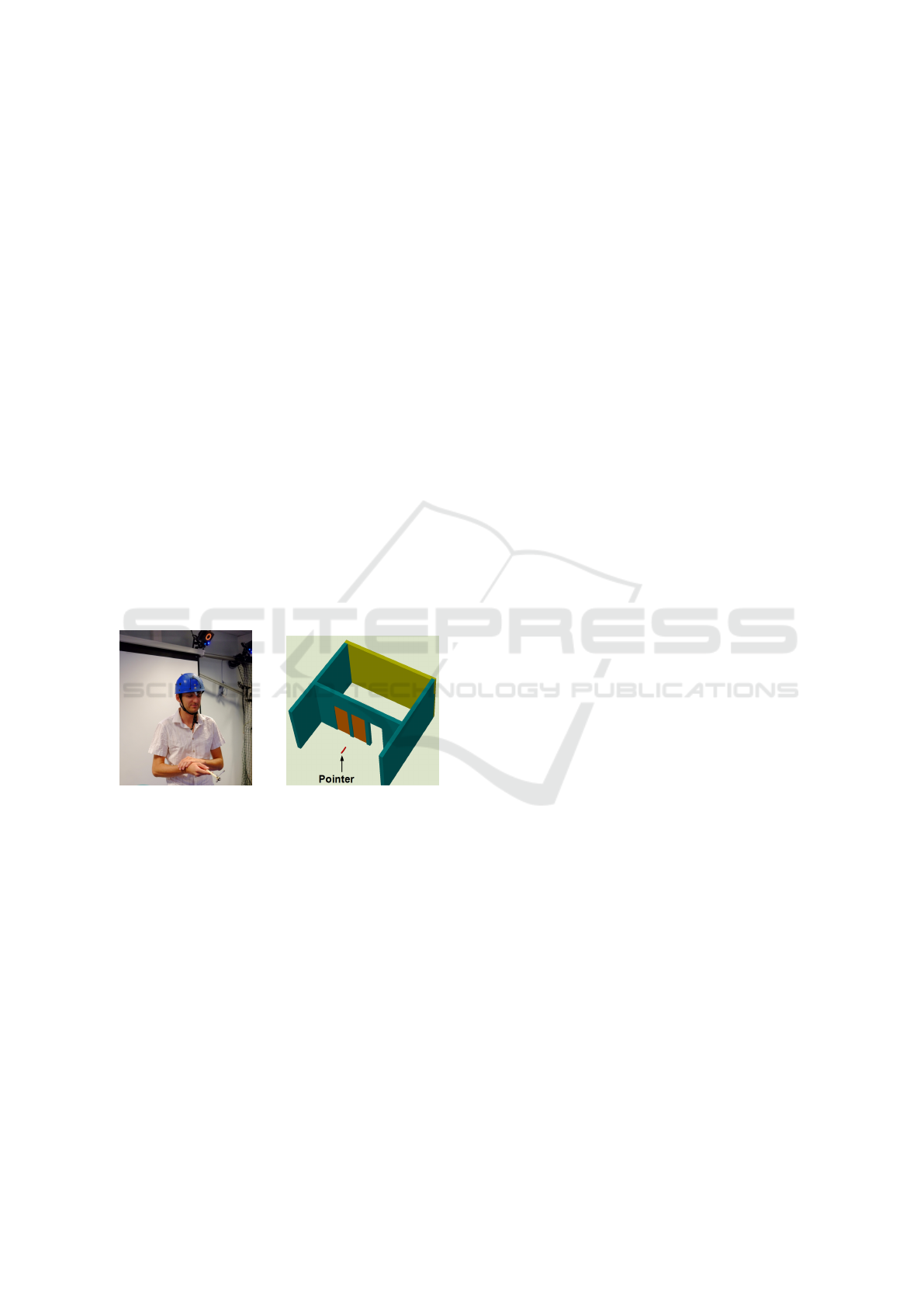
3.2 Second Experiment: Walking
through an Open Door Separating
Virtual Rooms
Figure 5: (left) Participant navigating and moving the
pointer in the real environment; (right ) pointer (red stick)
moving in the virtual environment.
Five young male participants, (Age: mean = 22.4
years-old, SD = 0.4), participated in this experiment.
Four of them had already done the first experiment.
They were immersed in a virtual environment
mimicking two rooms (LxW=5x3m) separated by
a partition wall (LxH=5x3m) that comprised three
doors, (LxH=0.8x2.0m), one of which was randomly
open at each trial (fig.5). The task of the participant
starting from the front room was to locate the open
door and walk through it into the back room.
The sound pitch f in Hz delivered by the SSD was
a monotonous function of depth d, i.e., distance from
the end of the pointing device to the next virtual sur-
face point in its direction. The function used, repli-
cated a preceding SSD (Twardon et al., 2013), is de-
fined by equation 4:
f = f
0
.2
(d
max
+d
min
−2d)/(d
max
−d
min
)
(4)
where f
0
is the reference frequency to be heard half-
way between d
min
and d
max
, d
max
and d
min
being the
upper and lower limits of d ; they are related to z
f
and
z
n
in equation (1). We used f
0
= 220Hz, d
min
= 0.5m
and d
max
= 4.5m.
Tests were organized in six blocks of six trials.
Each block comprised twice the three different door
positions. Each trial started with the onset of the
sound feedback, the participant standing 1.5m in front
of the center door. The sound was continuous but
when the pointer collided with a virtual wall, the
sound was interrupted for two seconds. When the
door was crossed and passed 1.0 m further, the sound
finally switched off and the participant returned to the
starting point. The response delay for the trial was
the time in seconds separating sound onset and final
sound offset.
Results. As well as for the first experiment, we used
a linear model with mixed effects to study the used
pointer, the door position and individual participant
effects on the crossing delay. The model is defined as
follows:
Y
pt,pos,par
= µ + α
pt
+ β
pos
+ τ
par
+ α
pt
β
pos
+ ε (5)
with Y
pt,pos,par
being the response delay (the log trans-
form of the delay in seconds), µ the mean delay, α
pt
and β
pos
the fixed effects respectively due to the point-
ing device and the door position, τ
par
the random ef-
fect due to the individual participant, α
pt
β
pos
the 2
nd
order interaction term and ε the error component (or
uncontrolled random effect) with ε → N(0,σ
2
2
).
Following a parsimonious and simplified pro-
cess of insignificant effects backward elimination, the
model defined in (5) can be simplified as follows:
Y
pt,pos,par
= µ + β
pos
+ τ
par
+ ε (6)
Thus, the door crossing delay only depends on the
door position and the participant and not on the
pointer used.
Conclusions. Multiple comparison tests shows that
the door position has a significant effect on door
crossing delay, the door at the center being faster
to cross than the doors beside, with significant dif-
ferences between individual participants. As for the
first experiment, pointing devices can be considered
as equivalent.
VISAPP 2018 - International Conference on Computer Vision Theory and Applications
600
4 CONCLUSIONS AND
PERSPECTIVES
The system described here has shown efficient for
evaluating SSDs and for designing novel ones. The
motion capture set-up on which it relies is an increas-
ing widespread tool that becomes constantly cheaper
and easier to use.
The two experiment series confirmed that immer-
sion in a virtual 3D space offers worthy means of test-
ing SSDs by conducting various tasks in various en-
vironments, such as identifying objects on a vertical
surface or navigating between rooms. In addition to
environments and tasks, they showed that the motion
capture system allows to easily interchange the point-
ers: any solid object can be converted to a pointer by
positioning markers on it.
The series of trials by human users showed that
both evaluated pointing devices, one held by hand
and the other fastened on the head, lead to equivalent
performances. Other criteria may therefore be taken
into consideration for a final choice in subsequent de-
velopment. Indeed, leaving hands free for other uses
represents a considerable advantage for the headset.
However, scanning around with head movements
proved to be quite uncomfortable for the participants.
In typical non blind navigation search, exploring
is essentially realized by eye saccades thus the am-
plitude of head movement remains limited. There-
fore, eye movements may direct the pointer leaving
both hands free and reduce head movements. These
advantages deserve to be tested, in the ultimate per-
spective of helping people whose eye muscles remain
functional while suffering of late retinal blindness. In
the line of (Twardon et al., 2013) and (Dietz et al.,
2016), we began to work on eye pointing for visual
sensory substitution.
!"#$%&'(
)*+"#,*-)*$
!"#$%&'
.)*.,#
/#&*.0,1)# 20$%&$,#
304(5&6)(+)0$,# "*($7)(-,$",*(
0&8$%#)(#)9)#)*$"&'
:,$",*(
0&8$%#)
;:<
"!")=>/5
;:<
"!")=>/5
?@AB@
3C4(5&6)(0,,#1"*&$). "*($7)(
D'&..).(#)9)#)*$"&'
3&4(5'&..).(0,,#1"*&$).
"*($7)(-,$",*(
0&8$%#)(#)9)#)*$"&'
VRPN
VRPN
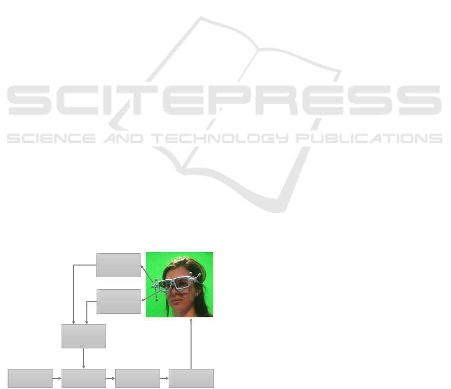
Figure 6: Experimental set-up with eye-tracker (see text for
more details).
Fig. 6 displays the evolution of our presented
experimental set-up to do studies on the pointing with
the eyes in the blind. It is based on a SMI portable
eye-tracker mounted on a spectacle frame equipped
with reflecting markers. Markers allow the VICON
system to determine the position and orientation of
the glasses (fig. 6(a)). The SMI iViewETG software
determines eye gaze coordinates within the glasses
referential (fig. 6(b)). Finally, the SMI 3D-6D
software merges these two information to deliver
the gaze vectors in the VICON system referential
through a VRPN server (fig. 6(c)). The genericity
offered by VRPN allowed to keep unchanged the rest
of the set-up. It is transparent whether the pointer is a
stick, a headset or the gaze. This prototype have been
currently tested by human participants in conditions
similar to the first experimental series.
Many other, hardware and software, implementa-
tions may be prototyped not only at the input level
(environment and sensors), but also at the transcoder
and the output level.
ACKNOWLEDGEMENTS
We would like to thank Silvain Gerber from GIPSA-
Lab for his availability and help on the statistical anal-
ysis of the experiments.
Graduate students in engineering, neurosciences
and psychology contributed to the project.
This work has been partially supported by the
LabEx PERSYVAL-Lab (ANR-11-LABX-0025-01),
the AGIR PEPS program of Univ. Grenoble Alpes
ComUE and the Pole Grenoble Cognition.
REFERENCES
Abboud, S., Hanassy, S., Levy-Tzedek, S., Maidenbaum,
S., and Amedi, A. (2014). Eyemusic: Introducing a
”visual” colorful experience for the blind using audi-
tory sensory substitution. Restorative neurology and
neuroscience.
Bach-Y-Rita, P., Collins, C. C., Saunders, F. A., White, B.,
and Scadden, L. (1969). Vision substitution by tactile
image projection. Nature, 221(5184):963–964.
Bates, D., M
¨
achler, M., Bolker, B., and Walker, S. (2015).
Fitting linear mixed-effects models using lme4. Jour-
nal of Statistical Software, 67(1):1–48.
Dietz, M., Garf, M. E., Damian, I., and Andr
´
e, E. (2016).
Exploring eye-tracking-driven sonification for the vi-
sually impaired. In Proceedings of the 7th Aug-
mented Human International Conference 2016, AH
’16, pages 5:1–5:8.
Prototyping and Evaluating Sensory Substitution Devices by Spatial Immersion in Virtual Environments
601

Hothorn, T., Bretz, F., and Westfall, P. (2008). Simultaneous
inference in general parametric models. Biometrical
Journal, 50(3):346–363.
Khoo, W., Seidel, E., and Zhu, Z. (2012). Designing a vir-
tual environment to evaluate multimodal sensors for
assisting the visually impaired. In Computers Helping
People with Special Needs, volume 7383 of Lecture
Notes in Computer Science, pages 573–580.
Kristj
´
ansson,
´
A., Moldoveanu, A., J
´
ohannesson,
´
O. I.,
Balan, O., Spagnol, S., Valgeirsd
´
ottir, V. V., and Un-
nthorsson, R. (2016). Designing sensory-substitution
devices: Principles, pitfalls and potential. Restor Neu-
rol Neurosci, 34(5):769–787.
Lahav, O., Schloerb, D. W., and Srinivasan, M. A. (2015).
Rehabilitation program integrating virtual environ-
ment to improve orientation and mobility skills for
people who are blind. Computers & Education, 80:1
– 14.
Maidenbaum, S., Buchs, G., Abboud, S., Lavi-Rotbain, O.,
and Amedi, A. (2016). Perception of graphical virtual
environments by blind users via sensory substitution.
PLoS One, 11(2):e0147501.
Stoll, C., Palluel-Germain, R., Fristot, V., Pellerin, D., Al-
leysson, D., and Graff, C. (2015). Navigating from
a depth image converted into sound. Applied Bionics
and Biomechanics, 2015:9 pages.
Twardon, L., Koesling, H., Finke, A., and Ritter, H. J.
(2013). Gaze-contingent audio-visual substitution for
the blind and visually impaired. In 7th International
Conference on Pervasive Computing Technologies for
Healthcare and Workshops, PervasiveHealth 2013,
Venice, Italy, May 5-8, 2013, pages 129–136.
VISAPP 2018 - International Conference on Computer Vision Theory and Applications
602
