
A New Approach for Reflection of Code Modifications to Model in
Synchronization of Architecture Design Model and Code
Van Cam Pham, Ansgar Radermacher and Sébastien Gérard
CEA, LIST, Laboratory of Model Driven Engineering for Embedded Systems, P.C. 174, Gif-sur-Yvette, 91191, France
Keywords:
UML State Machine, Code Generation, Change Reflection, Programmers, Software Architects, C++, Java
Annotation Processing, Programming Language, Component-based Design, Source Code Organization,
Incremental Reverse.
Abstract:
Model-Driven Engineering (MDE) increases the abstraction level, thus facilitates the design of complex sys-
tems. It is possible to create an executable system from a model enriched with detailed behavior specifications.
But the graphical modeling of some system aspects is likely less efficient compared to writing code in a pro-
gramming language. For method signatures, textual editing includes a few lines of text, whereas modeling
requires the separate addition of methods along with their parameters. Therefore, we propose to develop sys-
tems by combining the strength of graphical modeling with programming languages by allowing a developer
to make changes in either notation and synchronize the result with the other one, respectively. Synchroniza-
tion between model and code is already supported by existing tools, but often restricted to structural elements
that have a 1-1 mapping. The synchronization of additional modeling aspects from the code, notably compo-
nent based modeling in UML and behavior in form of state-machines, is not supported by the state-of-the-art.
In order to enable this synchronization, it is important to reduce the abstraction gap and assure a 1-1 map-
ping if possible. Our proposition is to perform the synchronization with an extended programming language
that provides additional language elements for some UML elements, notably those that do not already exist
in object-oriented programming languages. This extension uses built-in language facilities, in case of C++
templates and preprocessor macros, and a design pattern that adds a shadow implementation.
1 INTRODUCTION
Model-Driven Engineering (MDE) (Selic, 2012) pro-
motes the use of graphical modeling languages to
describe software architectures in an abstract way.
Abstract models provide an efficient way to manage
complexity of large systems. A number of existing
approaches in the context of MDE allow to automat-
ically produce implementations from software archi-
tecture models.
However, graphical modeling is not always the
most efficient way to create a detailed model (Jolak
et al. 2017). For some elements such as method signa-
tures, textual editing is much easier. Thus, modeling
can become more efficient if there is a mechanism that
allows to seamlessly switch between graphical and
textual representations, notable code. Furthermore,
complex system development often involves differ-
ent actors who prefer to use various tools to modify
model and code. Modifications raise the problem of
synchronization of model and code. The synchroniza-
tion requires to reflect changes in code back to the
model.
Reflection of code modifications is relatively easy
if there is a direct mapping between modeling ele-
ments and associated code fragments. This is the case
for UML structural aspects such as attributes, but not
for behavior aspects. The reflection becomes in par-
ticular difficult, if a model-to-model (M2M) transfor-
mation is executed before code generation. For exam-
ple, the process of producing code from UML state
machines consists of a M2M transformation and a ba-
sic code generation in case of our tools. The term ba-
sic code generation means to generate object-oriented
code from an object-oriented UML design in which
bodies of class operations are provided as blocks of
texts.
In the context of UML-based MDE for reac-
tive systems, we use UML composite structures and
state machines to describe software architecture. We
identify two issues related to the reflection of code
changes to the software architecture model. The
496
Pham, V., Radermacher, A. and Gérard, S.
A New Approach for Reflection of Code Modifications to Model in Synchronization of Architecture Design Model and Code.
DOI: 10.5220/0006610904960503
In Proceedings of the 6th International Conference on Model-Driven Engineering and Software Development (MODELSWARD 2018), pages 496-503
ISBN: 978-989-758-283-7
Copyright
c
2019 by SCITEPRESS – Science and Technology Publications, Lda. All rights reserved
first issue is how to organize code for modeling el-
ements of UML state machines and composite struc-
tures since a model element often results in multiple
lines of code in different places. The second issue is
how to identify code modifications, map and reflect
them to appropriate model elements. Both issues are
related, since a better organization of the code facil-
itates the identification of the associated model ele-
ments. The main cause of the two issues is that there
is a significant abstraction gap between the model el-
ements and code.
In this paper, we extend an existing program-
ming language by adding additional programming
constructs for modeling elements that have no repre-
sentation in code. The additional constructs provide a
way for efficiently organizing source code and iden-
tifying modified code elements related to modeling
elements. Source code using the additional constructs
is written in a descriptive way. Furthermore, we pro-
vide an in-place text-to-text transformation that acts
as a preprocessing step to make the additional con-
structs executable. Then, we define a reverse engi-
neering process that allows to reflect modified code
elements back to model elements.
The remaining of this paper is organized as fol-
lows: Section 2 describes a motivating example. Sec-
tion 3 presents the additional programming constructs
and how generated code is organized based on the
constructs. Section 4 proposes an incremental reverse
engineering to propagate code modifications back to
model. An evaluation of the approach based on a case
study is presented in Section 5. Section 6 discusses
related work. The conclusion and future work are pre-
sented in Section 7.
2 MOTIVATING EXAMPLE
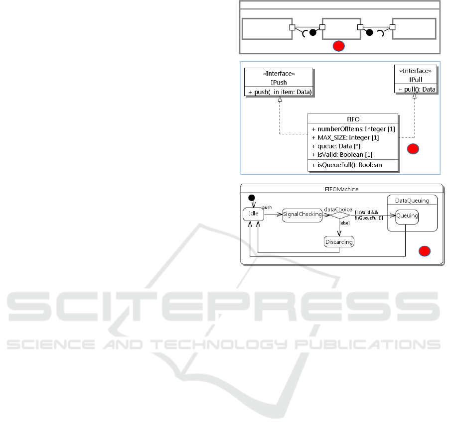
In this section, a motivating example is presented. We
consider a producer-consumer example, whose archi-
tecture model is shown in Fig. 1. This example is fic-
titiously created for illustration purposes only and it
might not fit to realistic usages. The p producer sends
data items to a first-in first-out component FIFO stor-
ing data. The FIFO queue has a limited size, the num-
ber of currently stored items (numberOfItems) and the
isQueueFull operation for checking whether it is full.
The pPush port of the producer with IPush as required
interface is connected to the pPush port of FIFO that
provides the IPush interface. The producer and FIFO
can interact with each other through their respective
port. FIFO also provides the IPull interface for the
consumer to get data items.
The behavior of FIFO is described by a UML state
System
p :
Producer
c :
Consumer
fifo:
FIFO
IPush
IPull
a
pPush
pPush
pPull pPull
b
c
Figure 1: Architecture model and generated extended code.
machine as shown in Fig. 1 (c). Initially, the Idle
state is active. The state machine then waits for an
item to arrive at the fifo part (through the pPush port).
The item is then checked for its validity before either
adding it to the queue or discarding it (if the queue is
full).
Ideally, code can be generated from the architec-
ture model by using a tool such as IBM Rhapsody
(IBM, 2016). Fine-grained behavior of operations
such as isQueueFull is embedded directly into the
model. However, if there are some bugs in the fine-
grained code, programmers might fix them by directly
debugging and modifying the generated code. Fur-
thermore, programmers might want to create methods
while writing fine-grained code within the generated
code for algorithms, for example. For those cases,
existing approaches cannot propagate code modifica-
tions such as creation of methods or attributes back
to the model because these modifications are outside
of modifiable areas. The separation of generated code
from user-code based on specialized comments is not
designed to propagate code modifications back to the
model. The separation mechanism relies on a code
generator that is specialized to recognize the special-
ized comments and keep the source code segment be-
tween them intact (Kelly and Tolvanen, 2007).
A New Approach for Reflection of Code Modifications to Model in Synchronization of Architecture Design Model and Code
497

3 BIDIRECTIONAL MAPPING
AND ORGANIZATION OF
GENERATED CODE
This section describes a new approach for organiz-
ing generated code in a way intended to support code
modifications. The approach is based the idea of ex-
tending an existing standard programming language
by adding programming constructs for modeling ele-
ments that have no direct representation in the code.
Notably, in the context of component-based design
and the use of UML state machines for describing be-
haviors of reactive system components, constructs for
port, connector, and state machine elements are intro-
duced. The programming language that contains the
additional programming constructs is called extended
language. This latter term has been first presented
in our preliminary work (Pham et al., 2017a). The
focus of this paper is on how the extended language
organizes the generated code in a way that is easy for
programmers to manage and for tools to identify code
modifications. Then, the code modifications are prop-
agated back to the model by an incremental reverse
engineering. The extended language contains all pro-
gramming constructs of the standard language plus
the additional programming constructs. Code con-
forming to the extended language is termed extended
code.
Fig. 1 shows an example of the extended code cor-
responding to the UML model from Fig. 1. The code
defines higher level elements such as states (line 33)
and ports (line 19). But it is not a new language. The
extensions are realized with the standard program-
ming language features, notably templates and pre-
processing macros. Therefore, the extended code is
actually written in a standard programming language
file, e.g. .h files for C++ headers and .cpp files for
C++ source files. We will later present the additional
constructs in more detail along with the example and
show how the organization of the extended code en-
ables code modification identification and propaga-
tion.
Port. A UML port does not have an equivalent el-
ement in standard code. In the extended language,
we propose programming constructs based on tem-
plate mechanisms of the standard language corre-
sponding to UML ports. RequiredPort<T> and Pro-
videdPort<T> are equivalent to UML uni-directional
ports, which have only one required or one provided
interface. The T template parameter is bound to the
interface required/provided by a UML port. Bidirec-
tionalPort<R,P> maps to UML bidirectional ports,
which have one R required and one P provided inter-
face. A UML port is then transformed into an attribute
typed by one of the port templates above.
The constructs enable a code parser to recognize
an attribute as a port so that a change propagation
mechanism can reflect the port attribute to the model.
It means that, the constructs are a means for explicitly
relating a code element to an equivalent element at the
model level. Existing tools such as Papyrus-RT trans-
form a UML port with a required interface into an
attribute typed by the interface. Unless using special-
ized comments for this transformed attribute, a code
parser cannot unambiguously understand it as a port.
The ambiguity leads to potential differences between
the original model used for code generation and the
model recovered from the code. Furthermore, these
constructs allow programmers to easily differentiate
between ports and actual class attributes.
At the modeling level, the creation of a port re-
quires two steps: (1) create a port and (2) specify the
required or provided interface. At the programming
level with the extended code, the effort for creating a
port is likely less compared to the graphical modeling
since a programmer only needs to create an attribute
in an object oriented programming language.
The purpose of adding new programming con-
structs is to: (1) provide a bidirectional mapping be-
tween model and code; (2) allow programmers to bet-
ter manage the code; and (3) allow programmers to
write fine-grained behavior of components using the
constructs: programmers can write code to call the
methods of a required and/or provided interface of a
port. To do it, the port type exposes one or two pub-
lic attributes: a requiredIntf attribute (a class attribute
in Java or a pointer attribute in C++, e.g.) typed by
the required interface of the required or bidirectional
port and a providedIntf attribute typed by the pro-
vided interface of the provided or bidirectional port.
For example, to call the push method implemented by
the FIFO from the producer, a programmer can write
pPush.requiredIntf->push(data) in fine-grained code
of the producer.
Binding. A binding connects ports on two parts. It is
equivalent to a UML connector that can connect two
UML ports. A method call to our predefined method
bindPorts connects two ports. A call of bindPorts
takes as input two parameters that are port references
corresponding to UML ports. For example, lines 7-
8 in Fig. 2 show two invocations of bindPorts for
two connectors. Each of the invocation takes as in-
put two ports (the two ports of the producer and the
fifo, for example). Each code class associated with a
UML component contains a single configuration (as a
method in lines 6-9) having invocations of bindPorts.
The configuration method is restricted to have only
invocations of bindPorts for easing change propaga-
MODELSWARD 2018 - 6th International Conference on Model-Driven Engineering and Software Development
498

1. class System {
2. public:
3. Producer p;
4. Consumer c;
5. FIFO fifo;
6. void configuration(){
7. bindPorts(p.pPush, fifo.pPush);
8. bindPorts(c.pPull, fifo.pPull);
9. }
10.}
11.class IPull {
12.public: virtual Data* pull() = 0;
13.}
14.class IPush {
15.public:
16. virtual void push(Data& data) = 0;
17.}
18.class Producer {
19.public: RequiredPort<IPush> pPush;
20.};
21.class Consumer {
22.public: RequiredPort<IPull> pPull;
23.};
24.class FIFO : public IPush, IPull {
25.public:
26. ProvidedPort<IPush> pPush;
27. ProvidedPort<IPull> pPull;
28. Data* pull(){//fine-grained code}
29. void push(Data& data){//..}
30. //attributes + methods…
31.Statemachine FIFOMachine {
32. InitialState Idle{};
33. State SignalChecking {
34. StateEntry entryCheck();
35. StateExit exitCheck();
36. };
37. State DataQueuing {
38. StateEntry entryQueue();
39. State Queuing();
40. };
31.State Discarding{};
32. PseudoChoice dataChoice{};
33. CallEvent(push(Data&)) DataPushEvent{};
34. TransitionTable {
35. ExT(Idle,SignalChecking,
36. DataPushEvent,NULL,signalCheck);
37. ExT(SignalChecking,dataChoice,
38. NULL,NULL,NULL);
39. ExT(dataChoice,Queuing,NULL,valid,NULL)
40. }
41.};
42.void entryCheck(){//fine-grained code}
43.void exitCheck(){//fine-grained code}
44.void entryError(){//fine-grained code}
45.void signalCheck(Data& item) {
46.//trans effect from Idle to SignalChecking
47.}
48.bool valid(){return isValid&&isQueueFull()}
49.}
Figure 2: Generated extended code for the producer-consumer example.
tion. Statements other than invocations of bindPorts
in the configuration method should not be used and
not synchronized back to the model.
Most of existing tools transform a connector into
multiple code elements at multiple places: a set-
ter method for the required port, a getter method
for the provided port, and a statement calling these
methods to assign the required interface attribute
of the required port to the appropriate implemen-
tation. In these tools, the connector between
the pPush ports of the p producer and the fifo
channel is transformed into two methods, namely
get_pPush and set_pPush, within the Producer and
Consumer classes, respectively. Furthermore, a state-
ment p.set_pPush(fifo.get_pPush()) is called within a
method of the FIFO class. These elements are famil-
iar to programmers but changing them is not intuitive.
In addition, it is not trivial for a code parser to eas-
ily recognize this statement as code elements trans-
formed from a connector.
In contrast, using the bindPorts method, program-
mers only need to manage invocations of this method.
A code parser can easily reflect the method calls as
connectors at the model level.
Other elements in the UML class diagram in Fig.
1 are mapped to corresponding code elements as they
are in industrial tools such as IBM Rhapsody (IBM,
2016). UML parts of a class, e.g. p, fifo, c, are
mapped to composite attributes of the corresponding
class at the code level, e.g. the System class; the
UML operations and properties are mapped to the
class methods and attributes, respectively; the UML
interfaces (IPush and IPull) are mapped to interfaces
in code, e.g. classes with pure virtual methods in C++
at lines 11-17 in Fig. 1.
State Machine. Behavioral programming constructs
are proposed corresponding to the UML state ma-
chine concepts at the modeling level. The model
elements of a UML state machine are transformed
into instances of these constructs. As shown in Fig.
2, these behavioral constructs are grouped into three
parts: topology, events, and transition table in the ex-
tended code.
A topology contains the constructs to describe the
state machine hierarchy. The root of the topology is
specified via the StateMachine as in Fig. 2. There-
fore, a state machine written in this style is easier to
maintain and manage than imperative code generated
by existing tools such as Papyrus-RT and IBM Rhap-
sody (IBM, 2016). A StateMachine contains vertexes.
Similarly to the concepts of vertexes in UML state
machines, a vertex can be either a state, which can in
turn contain one or more regions, or a pseudo state. A
state can have actions such as entry, exit, and doAc-
tivity. Those methods are declared within the state
and implemented in the class containing the state ma-
chine. For example, the entryCheck and exitCheck ac-
tions at lines 34-35 in Fig. 2 are implemented in the
FIFO class at lines 52-53. For modification reflec-
tion, a method implemented within a class is checked
whether its declaration appears within the state ma-
chine of the class. If so, the method is understood as
an action of the state that declares the method. Using
this strategy, the state actions in code can be unam-
biguously reflected to appropriate model elements.
Each state machine can define multiple events
that are processed by it. There are four event types,
namely call event, signal event, time event and change
event. They are described by the UML specification
and out of scope of this paper. Those events are unam-
biguously mapped to code in a bidirectional way. For
example, line 43 in Listing 2 shows a call event that
an instance of it is emitted if the associated method
push of FIFO is called.
A transition table consists of declarations of tran-
sitions of the state machine. Lines 45-49 in Fig. 2
show three transitions. Each transition is identified
by a source, a target vertex, an event that triggers it,
a guard method and a transition effect. The organi-
zation of code for the guard and effect methods are
similar to that of state actions: they are declared in
the transitions of the transition table and implemented
A New Approach for Reflection of Code Modifications to Model in Synchronization of Architecture Design Model and Code
499

within the class of the state machine. By this way, the
code reflection process can identify which methods of
the class of the state machine are part of transitions.
Transformation as Preprocessing. The additional
constructs are created by means of built-in features,
such as macros and annotations, of the standard pro-
gramming language. Therefore, the extended code is
syntactically valid to the standard language and thus
compilable by standard compilers such as GCC. How-
ever, it is in general not possible to expand the ad-
ditional constructs to executable code by using these
features, e.g. expand some macros for executable
code of state machine. In fact, a text-to-text trans-
formation that acts as a preprocessing step takes the
extended code into account to produce an additional
code, namely delegatee code. The delegatee code and
the extended code are then compiled together to cre-
ate an executable.
Let’s explain more clearly why there is a need to
have the transformation. The extended code and the
transformation act exactly similar to annotated Java
code and a Java annotation processing (Pawlak et al.,
2016) in case of Java at compile time. In Java, an-
notations are means used for embedding metadata in
program code and are used as markers for altering the
behavior of the annotated program code. Fig. 3 shows
how the alteration is realized by generating additional
source code based on a set of code generation tem-
plates and the semantics of the annotations (Deors,
2011). First, annotated Java source code is parsed for
extracting a semantics model of the annotations in the
code. Secondly, the annotation processing takes the
semantics model and the code generation templates
to produce a set of newly generated classes. The final
program is composed of the annotated Java code and
the generated classes.
Projecting the extended code and the transforma-
tion in the paper into the Java annotation process-
ing, the extended code, model semantics, text-to-text
transformation and delegatee code correspond to the
annotated Java code, the annotation semantics model,
the annotation processing and the generated classes,
respectively. The difference is that the model ele-
ments in the paper have their own semantics and use a
set of UML code generation templates for producing
the delegatee code.
For state machine elements, we use the set of pat-
terns presented in our previous work (Pham et al.,
2017b) because it provides efficient code generation
from all state machine elements. For ports and con-
nectors, we reuse the getter and setter-based patterns
of IBM Rhapsody. Thus, the extended code is exe-
cutable from developer perspectives similarly to the
execution of an annotated Java program.
Annotated
Java code
Code generation
templates
Annotation
semantics model
Annotation parser
Annotation
processing
Generated classes
Final program
Figure 3: Annotation processing in Java.
In the next section, we show how modifications in
the extended code are propagated by an incremental
reverse engineering.
4 INCREMENTAL REVERSE
ENGINEERING
Modifications in code should be automatically prop-
agated back to the model. This section presents our
proposition for dealing with it. Specifically, we pro-
pose an incremental reverse engineering (Pham et al.,
2016). Incremental reverse engineering is similar to
change-driven transformation (Ráth et al., 2009). The
latter listens to changes made in a model and uses pre-
defined rules to propagate the changes back to another
model. However, change-driven transformation can-
not be applied directly to propagate changes in code
back to the model because the detection of changes
in code is non-trivial. In our approach, we use a File
Tracker to detect which code files are changed by de-
velopers. The details of our approach are shown in
Fig. 4.
The file tracker monitors all extended code files
generated from the model. After modifications have
been made in the extended code, the tracker returns
a list of modified files. We do not allow renam-
ing or deleting a class because doing these modifi-
cations at the code level requires doing some addi-
tional re-factorings. For example, deleting a class re-
quires re-typing class attributes typed by this deleted
class. We believe that working at the model level
is more suitable for these modifications because the
re-factorings can be done through code re-generation
from the modified model.
The modified files and the model are then used
as input for reverse engineering to update the model.
For each modified file, the incremental reverse engi-
neering for each code element in the file follows a
Update-Create-Delete strategy described in the fol-
lowing list.
• Update: Find a model element matching the code ele-
ment by using name and type of the code element. If
MODELSWARD 2018 - 6th International Conference on Model-Driven Engineering and Software Development
500
Architecture
model
Extended Code
Modified extended Code
Modified Non-modified
File
tracker
Code generation + In-place transformation
Monitoring
File
categorization
Incremental reverse
engineering
Input
Input
Updated
model
Incremental
reversing
Modification
*
*
Figure 4: Incremental reverse engineering with file tracker
it exists, use the information of the code element to up-
date the model element. That is, every code element
that has its associated model element is considered as
updated element regardless of whether it is really mod-
ified at the code level. For example, if we modify the
entryCheck method body in Fig. 2, the incremental re-
verse engineering will propagate the changed body to
the architecture model as a block of text.
• Create: If no matching model element is found, create a
model element corresponding to the code element. For
example, if a programmer adds a state to the state ma-
chine example in Fig. 2, a UML state will be created in
the model.
• Delete: UML elements (attributes, ports, connectors,
methods, state machines, and events), which are not
updated or created by the Update and Create actions
during the incremental reverse engineering, are deleted.
Because it implies that these elements are removed by
programmers during code modification (since the Up-
date step does not find these elements)
1
.
It is worth noting that a renaming in code will be
considered as an addition followed by a deletion at the
model level. This detection of renaming is pretty bad
since modeling relies on unique references. There-
fore, we develop an additional code change listener.
This listener only detects renaming of code elements
including classes, attributes, methods, and state ma-
chine elements. If one of these elements is renamed,
the incremental reverse engineering simply updates
the corresponding element in the model with the new
name. The propagation of rename modifications is
executed before the Update-Create-Delete strategy
to avoid the detection of renaming changes as above.
If an element is renamed at the code level, its cor-
responding model element is updated with the new
name first. Then, in the Update-Create-Delete strat-
egy, the Update action finds the updated model ele-
ment and the Create and Delete do not have an effect
on this element.
In the next section, we describe the evaluation of
the approach based on a case study.
1
We reflect code modifications to the model to keep it
consistent with the code. If a model elements is neither up-
dated nor created from a code elements, it is not consistent
with the code, thus should be removed from the model.
5 CASE STUDY: LEGO CAR
This section presents the application of the approach
to the development of a realistic case study. The ob-
jective is to evaluate the feasibility of the approach
and the correctness of the reflection of code modi-
fications. Specifically, if generated code in the new
code organization approach is modified, can the code
modifications be propagated back to the model by the
incremental reverse engineering?
The case study is an embedded software for
LEGO. The LEGO car factory consists of small
LEGO cars used for simulating a real industrial pro-
cess (CEA LIST, 2016). It is chosen for the evalua-
tion because it is a real world embedded system with
enough complexity.
A LEGO car is composed of four modules: chas-
sis, front, back, and roof. Each module consists
of five components: bluetooth communication con-
troller, conveyor, robotic arm, press, and shelf. The
behavior of each component is described by a UML
state machine. The components communicate with
each other through ports. To adopt a fully component-
based approach, in the design model, we use service
ports and flow ports
2
to connect (call APIs and send
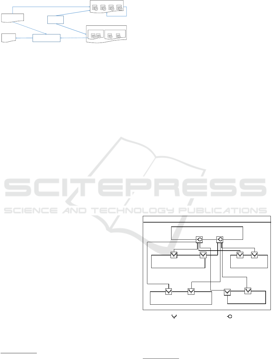
signals) the components within a module. Fig. 5
shows the UML composite structure diagram for the
front module without showing detailed structures of
each of its components. For simplification, only some
service ports are shown in the figure.
FrontModuleSystem
+ convoyer: FrontConveyor [1]
+ controller : FrontControlComponent [1]
+ pLCD: ILCD [1]
+ pModule: IModule [1]
+ roboticArm: FrontRoboticArm [1]
+ shelf: SlaveShelf [1]
+ press: SlavePress [1]
Legend Required port Provided port
Figure 5: Composite structure diagram of the front module
for flow ports.
In the experimentation, for each code generated
from the module design, we added class attributes
2
Ports that are used specifically for exchange data/sig-
nals between components. The details of these ports are not
presented here due to space limitation.
A New Approach for Reflection of Code Modifications to Model in Synchronization of Architecture Design Model and Code
501

and fine-grained code to each component. Specifi-
cally, state actions, transition effects, and class meth-
ods are created following the rules described in Sec-
tion 3. Furthermore, API invocations and exchange
of messages/signals between components are realized
through the use of service and flow ports and invoca-
tions through the required interface of the ports. For
example, Fig. 5 shows that the controller provides
two interfaces: ILCD and IModule for other compo-
nents to interact with. Note that, there are other con-
nectors connecting other ports of the components that
are not shown in the figure due to space limitation and
for simplification.
We generated code from the design and enriched
the generated code with fine-grained behavior of
methods, state actions and transition effects. We then
automatically propagated the code modifications back
to the corresponding model by using incremental re-
verse engineering. We then manually checked the
model for updates as follows:
• Are UML properties created in the model corre-
sponding to the class attributes in the code?
• Are UML state actions and transition effects cre-
ated within the model? Has each a block of text
containing the fine-grained code filled in the ex-
tended code?
• Are UML operations created in the model corre-
sponding to the class methods in the code?
All of the model elements corresponding in the
modified elements in the code were found in the up-
dated model. The resulting compilable code contains
on average 12000 lines of code: 11193 for chassis,
12246 for front, 12232 for roof, and 12245 for back.
More information about the code is not presented here
due to space limitation and can be found at (Pham,
2017). This result assesses that our approach and its
implementation can propagate modifications in code
back to model.
6 RELATED WORK
Several tools such as Enterprise Architect (SparxSys-
tems, 2016) and IBM Rhapsody (IBM, 2016) support
code generation from UML class and state machine
diagrams, and reverse engineering from code to UML
classes. Reverse engineering support in these tools is
not applicable to code generated from UML compos-
ite structures and state machines. A few approaches
(Chardigny et al., 2008) are able to recover compo-
nents from object-oriented code, based on heuristic
algorithms. However, the recovered models in these
approaches are often different from the original mod-
els.
Some techniques use specialized comments
(Steinberg et al., 2008) such as @generated NOT to
preserve code modified by programmers from gener-
ated code. However, this approach assures that code
modifications are not overwritten during code regen-
eration, but it is not possible to synchronize model-
code. Furthermore, if accidental changes happen to
the special comments, modified code cannot be pre-
served.
Textual modeling languages (TMLs) such as
Umple (Badreddin et al., 2014) unify modeling and
programming. They provide bidirectional mapping
to certain UML elements. The difference to our ap-
proach is that the extended code in our approach is
valid to programming language code and can be pro-
cessed by standard compilers such as GCC for C++
while the TMLs are not. In our approach, program-
mers can use their favorite IDEs while the use of
TMLs forces programmers to change their working
environment. In (Maro et al., 2015), the authors in-
tegrate graphical and textual editors for UML profiles
to allow developers to work in both of the representa-
tions. However, this approach depends on EMF and
embeds all modeling concepts, including classes and
attributes, to textual editors while our approach only
introduces necessary concepts in order to enable pro-
grammers to use their favorite programming language
in an MDE context.
The idea of adding more constructs for object-
oriented languages is similar to ArchJava (Aldrich
et al., 2002). This latter adds structural concepts such
as parts and ports to Java to support the co-evolution
of architecture structure and Java implementation.
However, ArchJava does not provide a mapping be-
tween architecture behavior and code. Furthermore,
ArchJava is not standard Java and not executed with
standard Java Virtual Machine, and facilities of IDEs
such as auto-completion are not compatible.
Our approach is inspired by the research challenge
proposed by Woods in (Woods and Rozanski, 2010).
The author of the latter argues that current practices
have a lack of architectural information in the imple-
mentation. This lack leads to a series of problems
related to software architecture such as outdated ar-
chitecture description or undesired recovered archi-
tecture from code. The author proposes to integrate
explicit architectural information into the implemen-
tation. A number of benefits of this integration are
discussed: (1) keeping implementation aligned with
architecture; (2) recovering an intended architecture
from its implementation; and (3) reducing the drift
between architecture and implementation.
MODELSWARD 2018 - 6th International Conference on Model-Driven Engineering and Software Development
502

7 CONCLUSION
The development of complex systems involves dif-
ferent actors. The latter use various tools to mod-
ify development artifacts, model and code in particu-
lar. Modifications of the artifacts raise the problem of
synchronizing model and code. Synchronization re-
quires to reflect modifications in code back to model.
The paper presented an approach for dealing with this
problem in the context of synchronization of software
architecture models specified by UML state machines
and component-based concepts and code.
The contributions allow programmers to effi-
ciently organize source code, modify it, identify code
modifications and automatically propagate it back to
the model. The approach is based on additional pro-
gramming constructs added to an existing program-
ming language and an incremental reverse engineer-
ing. The additional constructs allow to unambigu-
ously map code elements back to model elements.
The additional constructs are made executable by a
text-to-text transformation-based preprocessing step.
The evaluation of the approach is based on a Lego
Car Factory as case study. We evaluate the correct-
ness of the incremental reverse engineering if code is
modified. The results show that modifications in code
can be propagated back to the model. Therefore, de-
velopers do not need to manually update model from
code.
In future work, we will evaluate how programmers
react to the new organized code. We intend to con-
duct an empirical study and assess the perception of
programmers of the additional constructs.
REFERENCES
Aldrich, J., Chambers, C., and Notkin, D. (2002). Arch-
Java: Connecting Software Architecture to Implemen-
tation. In Software Engineering, 2002. ICSE 2002,
pages 187–197. IEEE.
Badreddin, O., Lethbridge, T. C., Forward, A., Elasaar, M.,
and Aljamaan, H. (2014). Enhanced Code Generation
from UML Composite State Machines. Modelsward
2014, pages 1–11.
CEA LIST (2016). LEGO Car Factory.
http://robotics.benedettelli.com/lego-car-factory/.
[Online; Accessed 22-Mar-2017].
Chardigny, S., Seriai, A., Oussalah, M., and Tamzalit, D.
(2008). Extraction of Component-Based Architecture
from Object-Oriented Systems. In Software Architec-
ture, 2008. WICSA 2008. Seventh Working IEEE/IFIP
Conference on, pages 285–288. IEEE.
Deors (2011). Code Generation using Annotation Proces-
sors in the Java language part 3: Generating Source
Code. [Online; accessed 06-Sept-2017].
IBM (2016). IBM Rhapsody. http://www.ibm.com/develop
erworks/downloads/r/rhapsodydeveloper/. [Online;
accessed 04-July-2016].
Kelly, S. and Tolvanen, J. P. (2007). Domain-Specific Mod-
eling: Enabling Full Code Generation.
Maro, S., Steghöfer, J.-P., Anjorin, A., Tichy, M., and Gelin,
L. (2015). On Integrating Graphical and Textual Ed-
itors for a UML Profile Based Domain Specific Lan-
guage: An Industrial Experience. In Proceedings of
the 2015 ACM SIGPLAN SLE, pages 1–12. ACM.
Pawlak, R., Monperrus, M., Petitprez, N., Noguera, C.,
and Seinturier, L. (2016). Spoon: A library for
implementing analyses and transformations of java
source code. Software: Practice and Experience,
46(9):1155–1179.
Pham, V. C. (2017). Github Test Lego Car. https://github.
com/phamvancam2104/test-lego-car. [Online; ac-
cessed 09-Aug-2016].
Pham, V. C., Li, S., Radermacher, A., and Gérard, S. (2016).
Foster Software Architect and Programmer Collabora-
tion. In 21th International Conference on Engineering
of Complex Computer Systems, ICECCS 2016, pages
1–10, Dubai, United Arab Emirates.
Pham, V. C., Radermacher, A., Gerard, S., and Li, S.
(2017a). Bidirectional mapping between architecture
model and code for synchronization. In Software Ar-
chitecture (ICSA), 2017 IEEE International Confer-
ence on, pages 239–242. IEEE.
Pham, V. C., Radermacher, A., Gérard, S., and Li, S.
(2017b). Complete code generation from uml state
machine. In MODELSWARD, pages 208–219.
Ráth, I., Varró, G., and Varró, D. (2009). Change-Driven
Model Transformations. In International Conference
on Model Driven Engineering Languages and Sys-
tems, pages 342–356. Springer.
Jolak, R., Umuhoza, E., Ho-Quang, T., Chaudron, M.R.V.
and Brambilla, M. (2017). Dissecting design effort
and drawing effort in UML modeling. In 2017 43rd
Euromicro Conference on Software Engineering and
Advanced Applications (SEAA) (pp. 384-391). IEEE.
Selic, B. (2012). What Will It Take? A View on Adop-
tion of Model-Based Methods in Practice. Software &
Systems Modeling, 11(4):513–526.
SparxSystems (2016). Enterprise Architect. http://www.
sparxsystems.eu/start/home/. [Online; accessed 20-
Nov-2016].
Steinberg, D., Budinsky, F., Merks, E., and Paternostro, M.
(2008). EMF: Eclipse Modeling Framework. Pearson
Education.
Woods, E. and Rozanski, N. (2010). Unifying Software
Architecture with Its Implementation. Proceedings
of the Fourth ECSA Companion Volume - ECSA ’10,
page 55.
A New Approach for Reflection of Code Modifications to Model in Synchronization of Architecture Design Model and Code
503
