
Pixel Apodization for the Suppression of Higher Diffractive Orders in
Computer Holography
Joanna Starobrat and Michal Makowski
Faculty of Physics, Warsaw University of Technology, ul. Koszykowa 75, 00-662 Warsaw, Poland
Keywords:
Computer-generated Holography, Higher Diffraction Orders, LCoS Spatial Light Modulator, Pixel Apodiza-
tion.
Abstract:
Demand for a next generation of head-up displays have increased the demand for the applicable holographic
displays. From the available spatial light modulators (SLM), Liquid Crystal on Silicon (LCoS) SLMs are the
most popular for the simplicity of addressing and their relatively low costs. However, improving its efficiency
demands reduction of higher diffraction orders. In this work we propose a new solution, that is the pixel
apodization as the means to redirect the light intensity from the undesirable images to the main image. The
higher diffraction orders are the result of the rectangular shape of the pixels of the SLM, as it can be concluded
from the Fourier Transform (FT) analysis. Hence we exploit the known property that a Gaussian function is,
up to a constant multiple, its own FT. The presented simulations support the theoretical conclusions, as the
apodization allows for a significant lowering of the intensity of the third and higher diffraction orders, in the
same time increasing the intensity directed to the main image.
1 INTRODUCTION
Holography as an imaging technique has been known
since the first half of XIX century (Gabor, 1949), with
its theoretical background dating as early as 1920
(Wolfke, 1920). Being a method which allows re-
construction of not only amplitude, but also phase
of the saved image, it has soon found its application
in a wide range of fields, starting from simple three-
dimensional image reconstruction (Denisiuk, 1978),
going through beam-shaping (Meltaus et al., 2003),
i.e. in particle-trapping (Reicherter et al., 1999),
telecommunication (Parker et al., 1997) or medicine
(West, 1976), ending with a modern idea of a holo-
graphic memory of high security (Betin et al., 2013).
In the modern days the demand for a next gen-
eration of displays has been increasing. The head-
up displays are an especially pursued subject, which
is one of the main reason for further development of
applicable holographic displays. Among the advan-
tages offered by this technology, creating a real 3D
images, low intensity-to-heat conversion and uncom-
plicated set-up of few elements can be named (Slinger
et al., 2005).
Though many different types of spatial light mod-
ulators (SLM) are used in order to change the ampli-
tude and/or phase of the wavefront (Casasent, 1977),
the liquid crystal on silicon (LCoS) are considered
the most popular due to their diffraction efficiency,
simplicity of pixel addressing and relatively low costs
(Michakiewicz and Kujawiska, 2009). The LCoS
SLMs technology is still, however, facing challenges
that remain to be overcome. While the pixel size is
limited by the production machinery and the crosstalk
between single liquid crystal cells occurs (Yang et al.,
2013), another issue has been chosen as the main sub-
ject of our research, and that is the presence of im-
ages in higher diffractive orders (Makowski et al.,
2012; Yaras et al., 2010). The state of art technol-
ogy employs spatial filtering as the method of re-
ducing the influence of the undesired images (Agour
et al., 2009). This approach allows to eliminate higher
diffraction orders, however, it largely decreases the
intensity of the final wavefront while also present-
ing difficulties with successful filtering of the highest
diffraction orders.
In this paper we conclude that the higher diffrac-
tion orders visible in a reconstruction of computer-
generated Fourier hologram are the result of the rect-
angular shape of the pixels. This judgement is based
on the analysis of both theory of the reconstruction of
the said type of a hologram, and known Fourier trans-
forms. Rectus function subjected to the FT results
in a sinc function (Kreyszig, 1988), characterised by
160
Starobrat, J. and Makowski, M.
Pixel Apodization for the Suppression of Higher Diffractive Orders in Computer Holography.
DOI: 10.5220/0006551901600165
In Proceedings of the 6th International Conference on Photonics, Optics and Laser Technology (PHOTOPTICS 2018), pages 160-165
ISBN: 978-989-758-286-8
Copyright © 2018 by SCITEPRESS – Science and Technology Publications, Lda. All rights reserved
multiple extrema in the spectrum. Thus, we propose
the effective change of the shape of pixels. As it is
known, a Gaussian function is, up to a constant multi-
ple, its own Fourier transform. We propose a change
of the pixel shape from rectus to a Gaussian function
in order to avoid the multiple maxima of the inten-
sity visible in the image reconstruction. Seeing as the
LCoS SLM production is limited by the LCD tech-
nology capabilities, changing not physical, but effec-
tive shape of the single SLM cells would be advis-
able. In our research we employ amplitude masks as
the means of altering the SLM effective structure.
2 PROPOSED METHOD
The high time-consumption and cost of employing
the suggested solution in an experiment led to a de-
cision of preparing and analysing simulations before
conducting the experiment itself. In the next sec-
tions the assumptions made for the theoretical model
of the hologram reconstruction are explained. In this
research, LightSword software was used, which en-
ables the simulation and numeric analysis of wave-
fronts propagation.
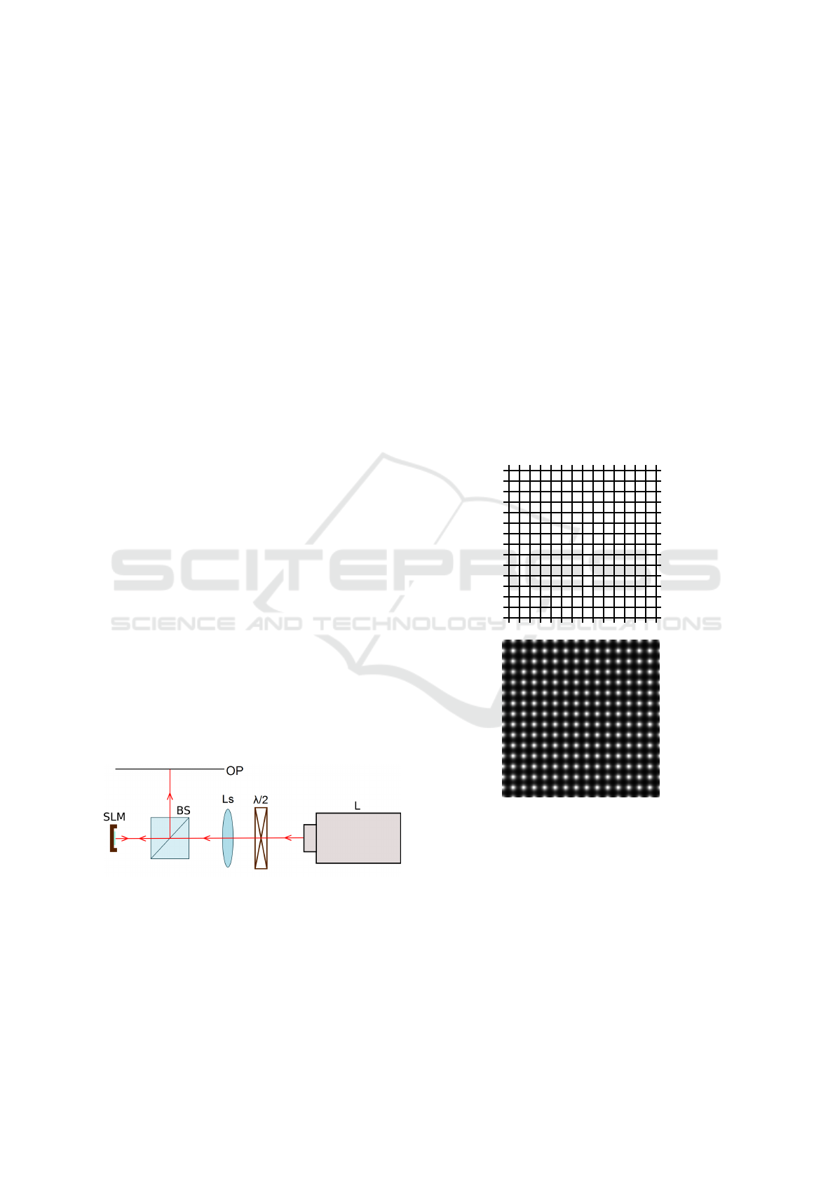
2.1 Simulated Set-up
A very simple set-up was chosen for the simulation
of image reconstruction from Fourier holograms, as
can be seen in Figure 1. He-Ne laser (λ = 632.8 nm)
serves as a light source, while a half-plate is used to
set proper polarisation in respect to the SLM. The lens
enables the reconstruction of the image in its focal
plane after wavefront reflects from the spatial light
modulator. Thanks to the beamsplitter, observing the
resulting intensity pattern to the side from the optical
axis of the set-up is possible.
Figure 1: A schematic diagram of a simulated experimental
set-up, where: L - He-Ne laser, λ/2 - half-wave plate, Ls -
lens, BS - beamsplitter, SLM - spatial light modulator, OP -
observation plane positioned in the focal distance from the
lens.
2.2 SLM Structure
In the simulations, an SLM of HoloEye Pluto type
was imitated as an amplitude distribution presented
in a numeric array. Said model is characterized by
the pixel size of 8 µm and the fill factor estimated as
93%, which implies the presence of spacing between
single pixels. It is caused by fabrication limitations
and needs to be considered in the theoretical model.
Despite the resolution of 1920 x 1080 pixels of the
SLM, only a matrix of 128 by 128 pixels was con-
sidered to simplify the simulations. To observe the
effects of the apodization, oversampling was applied.
This means that a square of 16 by 16 sampling points
corresponded to a single SLM pixel and the final array
size was 2048 by 2048. Such structure was approxi-
mated as a rectangular lattice consisting of squares
with 7 µm sides and 1 µm spacing between them. A vi-
sualised fragment of a created structure is presented in
the Figure 2.
Figure 2: Fragments of the simulated structures. Top: am-
plitude distribution of the SLM pixel structure. Bottom:
amplitude distribution of the Gaussian mask.
2.3 Masks Generation
As mentioned in the previous sections, a Gaussian
shape of the pixels was proposed as a solution to the
intensity leakage to the higher diffraction orders. The
change of the effective pixel shape implies that each
pixel needs to be apodized with a required function.
For that reason, a lattice of desired elements had to
be generated. In this case, the Gaussian functions of
Pixel Apodization for the Suppression of Higher Diffractive Orders in Computer Holography
161
a set radius were applied. A range of different radii
values were considered, spanning from w
1
= 4 µm,
through w
2
= 3.5 µm and w
3
= 3 µm, to w
4
= 2.5 µm.
Like in the case of the SLM structure, oversampling
was applied and the same size of an array was used
(2048 x 2048).
Bottom part of Figure 2 shows a fragment of the
amplitude mask structure of w
4
= 2.5 µm. Notably,
centres of each square pixel and each Gaussian func-
tion were aligned for correct apodization.
The postulated Gaussian shape of the pixels might
not be the optimal solution. Not only is it possi-
ble for another, more efficient mask to exist, but the
difficulty of practical application is also an influen-
tial factor. For that reason a sinusoidal amplitude
mask was simulated and analysed alongside the Gaus-
sian masks. The period of the sinusoid function was
matched to the pixel period of the SLM structure.
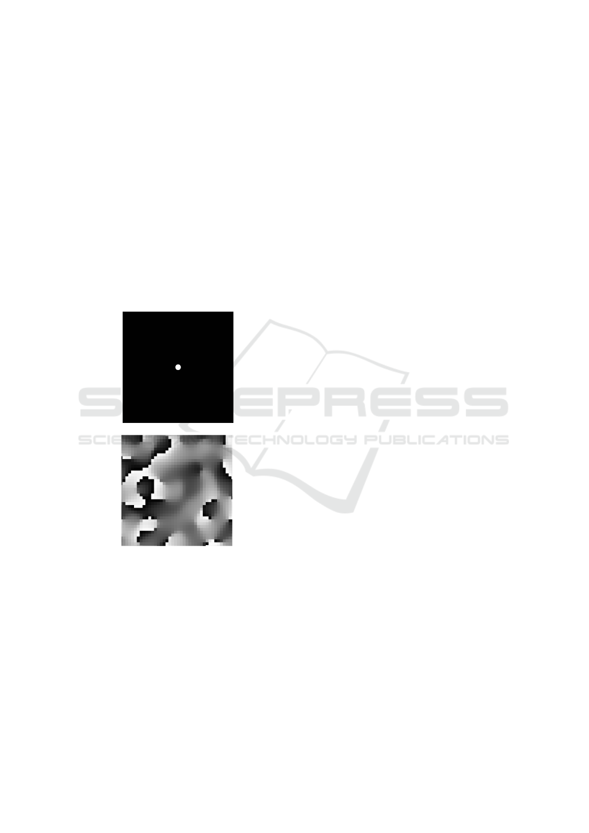
Figure 3: Computer-generated Fourier hologram. Top: sim-
ulated image. Bottom: fragment of the phase distribution of
the hologram.
2.4 Fourier Hologram
Fourier hologram is a unique type of a hologram be-
cause of it saving the Fourier spectrum of the recorded
image. The image can be reconstructed, as in the
set-up shown on Figure 1, by a convergent spherical
wave. In a computer-generated hologram, a Fourier
transform of the simulated wavefront is calculated.
Then, it is presented in an array of values correspond-
ing to the phase change that is necessary to create
a desired distribution.
A simulation utilizing a simple image of a small
circle (Figure 3) was chosen to be presented in this pa-
per due to the simplicity of obtained results and their
viable analysis. A hologram of a size 128 by 128 pix-
els was generated, and only then it was rescaled to
match the matrices prepared in the previous sections,
that is to the size of 2048 x 2048. This allowed a uni-
form distribution of phase in the areas corresponding
to single SLM pixels, which were set to have a side of
16 pixels.
3 SIMULATIONS
In order to conduct the simulations, all elements
whose generation was described in the previous sec-
tion must be combined. The SLM structure was first
merged with the Fourier hologram phase distribution,
and then mathematically multiplied by the amplitude
mask as to simulate the apodization. While all the
generated masks were applied, also a case of un-
apodized spatial light modulator was studied as the
reference for further results. It should be noted that
the zeroth diffraction order, present in the experimen-
tal hologram reconstruction, was not simulated, as the
crosstalk effect between the pixels was omitted in the
theoretical model.
The obtained wavefront amplitude distributions
were analysed by two different methods. First of them
was based on the visual presentation of the simula-
tion results. Even though the differences between the
obtained images were noticeable with bare eyes, the
cross-sections of the distributions were calculated for
improved assessment of the effectiveness of apodiza-
tion. Figure 4 presents the examples of the acquired
images and the cross-sections for the cases of no
apodization, as well as Gaussian masks of w
1
= 4 µm
and w
4
= 2.5 µm.
The visual judgement is known to be insufficient
as the means of theory evaluation, therefore the nu-
merical results were also analysed and are demon-
strated in the Tables 1 and 2. The values were ob-
tained by the integration of the selected areas of
first, second, as well as joint third and fourth or-
ders of diffraction. The results shown in the Table
1 present the percentage of the amplitude distribution
in each examined case separately, while in Table 2
normalized percentage distribution of amplitude can
be found. The values given in the tables do not total
up to 100%, as as the diffractive orders higher than
fourth were not included.
PHOTOPTICS 2018 - 6th International Conference on Photonics, Optics and Laser Technology
162
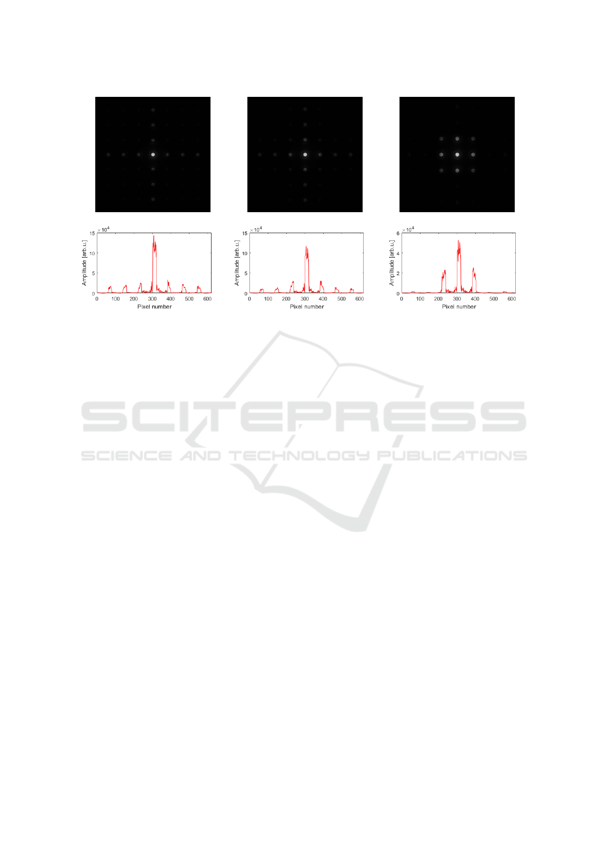
Figure 4: Amplitude of the image reconstructions from simulated holograms and the cross-sections of their distributions.
Left: image obtained with an un-apodized spatial light modulator. Center: image obtained with the use of a first examined
Gaussian mask, w
1
= 4 µm. Right: image obtained with the use of a last examined Gaussian mask, w
4
= 2.5 µm.
4 DISCUSSION
The visual results are rather simple to analyse, as the
difference in hologram reconstructions is rather no-
ticeable. Both Gaussian masks, including the one of
the highest Gaussian diameter, redirects light into the
main image, which corresponds to the first diffrac-
tion order. Said effect is more visible in the case of
the smaller Gaussian diameter, w
4
. On the presented
cross-sections the relative lowering of the amplitude
of the third and higher diffraction orders can easily be
observed.
The numeric values of the area integrals allow for
a more precise comparison. Even at a first glance,
a trend among the Gaussian masks is rather visible,
with monotonous decrease of the amplitude of third
and fourth diffraction orders, and increase of the first
diffraction order, that is, the amplitude of the main
image. The notable increase in the second order of
diffraction is, however, undesired. Yet, it could be re-
duced by the means of spatial filtering - combining the
state of art technology with the method suggested in
this paper could result in the increase of the intensity
of the main image.
It is therefore crucial to analyse the normalized
percentage distribution of the amplitude in respective
diffraction orders, as presented in the Table 2. As
expected, the trend of decreasing amplitude integrals
in the area of the first diffraction order is noticeable.
Despite redirecting more percentage of light into the
main image, the large part of the wavefront is blocked
due to applying the amplitude mask. The decrease
in the first order is as big as 41.5 percentage points
(pp) between the un-apodized spatial light modulator
and the Gaussian mask of the smallest diameter, w
4
.
However, for the third and fourth diffraction order the
reduction is much more significant, coming close to
95 percentage points. Again, in the second order of
diffraction an undesired rising tendency is observed,
with the amplitude increasing even despite the light
suppression by the amplitude mask.
It is worth noting that the numeric results for the
sinusoidal mask are rather similar to those obtained
with a Gaussian mask of w
4
= 2.5 µm. In the case of
amplitude percentage in the respective diffraction or-
ders, the value of the third and fourth orders is slightly
lower (by around 3 pp) and the main image is also
somewhat stronger (0.5 pp increase of the amplitude
value). The normalized amplitude show a decrease in
both of these areas (both by around 4-5 pp) in com-
parison to the Gaussian mask of w
4
. While the two
analysed data sets prove the rise of the amplitude in
the second diffraction order, the simplicity of applica-
tion of this mask, as explained in the next section, is
an advantage enough to consider the results satisfac-
tory.
Despite the seemingly undesired effect on the sec-
ond order of diffraction, which is as well the closest to
the main image and therefore can strongly influence
the quality of the image reconstruction from Fourier
hologram, the apodization simulation has proven the
possibility of changing the effective pixel shape. As
Pixel Apodization for the Suppression of Higher Diffractive Orders in Computer Holography
163
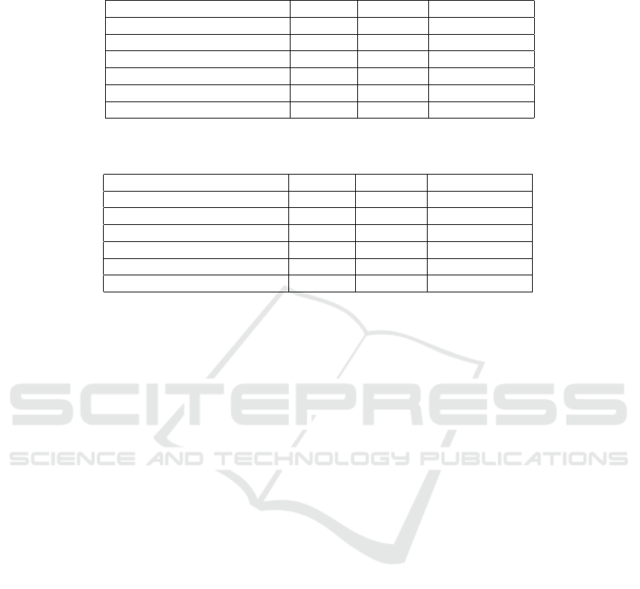
Table 1: Percentage of amplitude distribution in respective diffraction orders for different apodizing masks - result of the
simulations.
Mask shape 1st order 2nd order 3rd & 4th order
No apodization 17,74% 15,76% 27,31%
Gaussian mask (w
1
= 4 µm) 19,29% 22,08% 24,59%
Gaussian mask (w
2
= 3,5 µm) 20,36% 28,30% 21,79%
Gaussian mask (w
3
= 3 µm) 21,64% 39,26% 16,52%
Gaussian mask (w
4
= 2,5 µm) 22,48% 55,51% 8,58%
Sinusoidal mask 22,99% 69,97% 5,34%
Table 2: Normalized percentage of the amplitude distribution in respective diffraction orders for different apodizing masks -
result of the simulations.
Mask shape 1st order 2nd order 3rd & 4th order
No apodization 100% 100% 100%
Gaussian mask (w
1
= 4 µm) 82,92% 106,84% 68,64%
Gaussian mask (w
2
= 3,5 µm) 66,19% 103,60% 46,03%
Gaussian mask (w
3
= 3 µm) 51,60% 105,37% 25,59%
Gaussian mask (w
4
= 2,5 µm) 38,50% 107,03% 9,54%
Sinusoidal mask 33,38% 114,40% 5,04%
predicted, the amplitude masks allowed a change of
the distribution of the reconstructed images and while
the results obtained are not yet ideal for the proposed
purpose, the conducted research creates the possibil-
ity of optimising the masks parameters. Additionally,
displaying the image in between the intensity peaks
of main diffraction orders with the use of a carrier-
frequency would have the advantage of increasing re-
construction efficiency with the observed gain of in-
tensity in both first and second order of diffraction.
5 EXPERIMENT
The simulations are the first step of confirming the
postulated hypothesis and because of the limita-
tions of theoretical models, experimental proof is
favourable. Especially the sinusoidal mask presents
the greatest opportunity of experimental application
due to its structure. In this paper we name a few of
the possible application approaches.
The simplest of them would be mask fabrication
and its positioning by the SLM surface in the set-up
analogous to the one presented in Figure 1. It should
be noted, however, that in such case the wavefront
propagates twice through the amplitude mask. The
shape of the mask should be then corrected. Using the
Talbot self-imaging length could eliminate said obsta-
cle, with the periodic structure reconstruction, up to
a constant multiple, at a distance. The mask itself can
be created precisely by the means of electrolitogra-
phy or, in a simplistic case, by recording a hologram
of an interference pattern of two plane waves, creat-
ing a sinusoidal structure in one of the dimensions.
In the latter instance, care should be taken to accu-
rately apply the correct angle between the waves. An-
other possible approach to the spatial light modulator
apodization is a direct interference of two waves on
the SLM plane.
6 SUMMARY
In this work, a solution to the intensity leakage in
the image reconstruction of the computer-generated
Fourier hologram was proposed. The higher diffrac-
tion orders are one of the reasons for the intensity de-
crease of the main image, thus we proposed the ef-
fective change of the pixel shape to reduce this effect.
The apodizing structures described in this paper, that
is Gaussian and sinusoidal masks, are not necessarily
optimal for this purpose, however, intensity redirec-
tion to lower diffraction orders was still observed. It
is a common practice to display the image off-axis
with the use of holographic diffraction gratings, thus
the final projection can benefit from the obtained in-
tensity raise of both first and second orders.
Conducted simulations support the hypothesis that
it is possible and relatively uncomplicated to alter the
obtained amplitude distribution by the use of the am-
plitude mask, and control the change by modifying
parameters of the mask. In order to analyse both
masks of different shapes and experimental results for
the simulated data, further study of the subject is nec-
essary.
PHOTOPTICS 2018 - 6th International Conference on Photonics, Optics and Laser Technology
164

REFERENCES
Agour, M. et al. (2009). Suppression of higher diffraction
orders and intensity improvement of optically recon-
structed holograms from a spatial light modulator. In
Journal of Optics A: Pure and Applied Optics, 11(10),
105405, 120-128.
Betin, A. Y. et al. (2013). Holographic memory optical sys-
tem based on computer-generated fourier holograms.
In Applied Optics 52, 8142-8145.
Casasent, D. (1977). Spatial light modulators. In Proceed-
ings of the IEEE, 65(1), 143-157.
Denisiuk, I. N. (1978). Holography. In Optiko Mekhanich-
eskaia Promyshlennost, 45, 9-13.
Gabor, D. (1949). Microscopy by reconstructed wave-
fronts. In Proceedings of the Royal Society of London
A: Mathematical, Physical and Engineering Sciences,
Vol. 197, No. 1051, pp. 454-487. The Royal Society.
Kreyszig, E. (1988). Engineering mathematics. Wiley, 10th
edition.
Makowski, M. et al. (2012). Simple holographic projection
in color. In Optics express, 20(22), 25130-25136.
Meltaus, J. et al. (2003). Millimeter-wave beam shaping
using holograms. In IEEE Transactions on Microwave
Theory and Techniques, 51(4), 1274-1280.
Michakiewicz, A. and Kujawiska, M. (2009). Opto-
electronic reconstruction of digital holograms. In
Elektronika: konstrukcje, technologie, zastosowania,
50(1), 120-128.
Parker, M. C., Cohen, A. D., and Mears, R. J. (1997). Dy-
namic holographic spectral equalization for wdm. In
IEEE Photonics Technology Letters, 9(4), 529-531.
Reicherter, M. et al. (1999). Optical particle trapping with
computer-generated holograms written on a liquid-
crystal display. In Optics Letters, 24, 608-610.
Slinger, C., Cameron, C., and Stanley, M. (2005).
Computer-generated holography as a generic display
technology. In Computer, 38(8), 46-53.
West, P. A. (1976). Holography in medicine. In Journal of
Modern Optics, 23(10), 845-845.
Wolfke, M. (1920). Uber die moglichkeit der optis-
chen abbildung von molekulargittern. In Physikische
Zeitschrft, 21, 495-7.
Yang, H. et al. (2013). Origin of transient crosstalk and
its reduction in phase-only lcos wavelength selective
switches. In Journal of Lightwave Technology, 31(23),
3822-3829.
Yaras, F., Kang, H., and Onural, L. (2010). State of the art in
holographic displays: a survey. In Journal of display
technology 6(10), 443-454.
Pixel Apodization for the Suppression of Higher Diffractive Orders in Computer Holography
165
