
Resonant Tunnelling and Optical-mechanical Analogy
Overcoming of Blackout Problem
Anna Bogatskaya
1,2,3
, Nikolay Klenov
1,3,4,5
and
Alexander Popov
1,2,4
1
Skobeltsyn Institute of Nuclear Physics, Moscow State University, 119991, Moscow, Russia
2
Lebedev Physical Institute, RAS, Moscow, 119991, Russia
3
Moscow Technical University of Communication and Informatics, 111024, Moscow, Russia
4
Department of Physics, Moscow State University, 119991, Moscow, Russia
5
Moscow Technological University (MIREA), 119454, Moscow, Russia
Keywords: Optical Mechanical Analogy, Resonant Tunneling, Interaction of Electromagnetic Radiation with Plasma,
Communication through Plasma Sheath.
Abstract: We report on using the optical mechanical analogy to study the propagation of the electromagnetic wave in
through the plasma layer surrounding the hypersonic object moving in dense gaseous medium. This analogy
allows us to consider plasma sheath surrounding the object as a potential barrier and analyse the process of
electromagnetic wave tunneling. The idea is to embed a dielectric layer as a «resonator» between the surface
of the object and plasma sheath which is supposed to provide an effective tunneling regime. We discuss the
peculiarities of optical mechanical analogy applicability and analyse the radio frequency wave tunnelling
regime in detail. The cases of normal and oblique incidence of radiofrequency waves on the vehicle surface
are studied. The analysis is applied for a problem of overcoming of the communication blackout during the
hypersonic vehicle re-entry into the Earth's atmosphere.
1 INTRODUCTION
Analysis of the tunneling processes for
electromagnetic waves in opaque media regions on
the basis of the well-known optical-mechanical
analogy is used in a huge number of applications.
Typically, these are problems in condensed matter
physics, magnetic hydrodynamics, quantum optics,
physics of photonic crystals and artificial
metamaterials with unique parameters (Shvartsburg,
2007; Narimanov and Kildishev, 2009; Yang et al.,
2012; Bobkov et al., 2016; Jung and Keller, 2017;
Razzaz and Alkanhal, 2017; Li, 2016).
We applied this approach to the solution of the
urgent communication blackout problem (Shi et al.,
2013; Lei et al., 2015; Xie et al., 2016). First, it
allowed us to propose new methods of optimization
of telecommunication systems with an ability of
continuous contact with the hypersonic vehicle. Also
new unobvious limitations on the region of
applicability of optical-mechanical analogy in
problems on the passage of electromagnetic waves
through layers/structures of extremely low
transparency are discussed. Aircraft, rockets, and
missiles moving at supersonic speed in the
atmosphere are covered with plasma sheath
(thickness d is about 0.1–1 meter). Hence we cannot
use for telemetry and control microwaves with
frequencies less than the so-called plasma frequency
(of about 9 GHz for object velocities in the range 8–
15 Mach) and wavelengths comparable or less then
d. We cannot ignore the presence of a plasma sheath
since it is the frequency range from 100 MHz to 10
GHz that is most important for prospective
telecommunication systems (Nazarenko et al., 1994;
Korotkevich et al., 2007; Gillman and Foster, 2009;
Wang et al., 2016; Gao and Jiang, 2015). Plasma
destruction (e.g. by injecting water drops) is also
quite a difficult task.
The most interesting approach is to use the
features of the interaction of ionized gas with
radiation. For overcoming the opaque layer one can
use the nonlinear interaction of three waves in the
plasma layer region: a low-frequency wave carrying
a signal from the Earth, a Langmuir wave and a
high-frequency wave (pump wave) generated from
the onboard source. The reflected (so-called Stokes
wave) carries the information encoded in the signal
to the Earth.
148
Bogatskaya, A., Klenov, N. and Popov, A.
Resonant Tunnelling and Optical-mechanical Analogy - Overcoming of Blackout Problem.
DOI: 10.5220/0006542901480154
In Proceedings of the 6th International Conference on Photonics, Optics and Laser Technology (PHOTOPTICS 2018), pages 148-154
ISBN: 978-989-758-286-8
Copyright © 2018 by SCITEPRESS – Science and Technology Publications, Lda. All rights reserved

Significant progress can be achieved if we
introduce an additional layer of double-positive
(DPS) material covering the antenna and providing
matching with the plasma sheath (Wang et al.,
2016).
In order to upgrade this concept, we suggest the
use of optical-mechanical analogy based on the
mathematical similarity of the stationary
Schrödinger equation with the wave Helmholtz
equation. This analogy allows us to introduce the
concept of tunneling of electromagnetic waves by
analogy with the tunneling of a particle through a
potential barriers in heterostructures (Hasbun, 2003;
Kidun et al., 2005). In the considered problem
plasma sheath may act as such a "barrier".
2 THE CONCEPT OF OPTICAL
MECHANICAL ANALOGY
Let us consider spatially inhomogeneous
nonmagnetic medium characterized by the suscep-
tibility
)(r
, or permittivity
)(41)( rr
. In
the case of monochromatic field
tirHrEHE
exp)(),(,
00
,
is the radiation
frequency) Maxwell equations for electric and
magnetic field strength can be written as:
.0,
,0,
1
HdivEi
c
Hrot
EdivHi
c
Erot
(1)
From (1) one can obtain the following equation for
electric field strength
E
:
.0)(
1
2
2
E
c
EE
(2)
For the case when permittivity depends only on one
spatial coordinate
)(z
and wave field
propagates alone this direction the equation (2)
transforms to the well-known Helmholtz equation
for the spatial distribution of electric field strength
E
:
.0))(41(
2
0
2
2
Ezk
dz
Ed
(3)
with
222
0
сk
. Here electric field propagates in
the direction perpendicular to z-axis.
Equation (3) is mathematically equivalent to the
stationary Schrödinger equation in quantum
mechanics for the particle wave function
)(z
in
the potential field
)(zV
:
.0
)(
1
2
0
2
2
zV
dz
d
(4)
where
22
0
2
m
is the wave vector of the
particle with energy
. Direct comparison of (3)
and (4) leads to the conclusion that potential
function
)(zV
in quantum mechanics is similar to
the susceptibility in electromagnetic theory
.)()(4)()1(
)()2(
22
2
czc
zVm
(5)
Thus the eigenvalue problem for the Hamiltonian in
quantum theory turns out to be mathematically
identical to the problem of calculating the stationary
distribution of the electric field strength in a wave.
The medium with
0
can be associated with an
attractive potential
0)( zV
(potential well) while
the medium with
0
acts as potential barrier
0)( zV
.
If the potential curve
)(zV
has the piecewise-
continuous structure (fig. 1), both the
-function
and its derivative
dxd
should be continuous
functions in the potential breaking points. Similar
boundary conditions appear to exist in
electromagnetic theory: the tangential components
of
HE
,
should also be continuous functions at the
interface regions. Using Maxwell equations one can
rewrite the boundary conditions as the continuity of
tangential components of
E
and its derivative. For
the normal incidence when only tangential
components of
HE
,
have the non-zero values these
boundary conditions are equivalent to boundary
conditions for the wave function in quantum
mechanics.
The above conclusion known as an optical-
mechanical analogy in quantum theory gives rise to
a lot of practical applications and transfer the
quantum theory problem solutions to optics and vice
versa. As an example, the quantum mechanical
tunnelling or the penetration of the quantum object
through the barrier with a height greater than its
kinetic energy is similar to the propagation of
electromagnetic wave through the region with
negative permittivity. It should be noted that plasma
is an excellent example of the media with negative
permittivity if the frequency of transmitted radiation
Resonant Tunnelling and Optical-mechanical Analogy - Overcoming of Blackout Problem
149
is less than the plasma frequency. Really, for the
collisionless plasma the permittivity reads
2
2
1
p
p
.
(6)
where
mne
ep
22
4
is the plasma frequency
squared and
e
n
is the electron density. From this
point of view the plasma sheath appearing around
the hypersonic vehicle during the flight looks like a
potential barrier for the target transmission
frequencies less than plasma frequency.
3 MAIN IDEA OF OVERCOMING
OF THE RADIO COMMUNICA-
TION BLACKOUT
In this section we are going to use the above
mentioned optical mechanical analogy to propose
the way of overcoming the communication blackout.
We consider the ideal conductive surface of vehicle
covered by the dielectric layer (thickness a) with
permittivity
d
and plasma sheath (thickness d)
with permittivity
p
that corresponds to the
potential well separated from the area of infinite
motion by a potential barrier (see fig. 1). Let us
imagine that quantum mechanical flux of particles
moves towards our structure. From classical point of
view this flux will be reflected from the barrier if the
energy of incoming particles is less than the height
of the barrier. From quantum-mechanical point of
view tunneling through the barrier is possible.
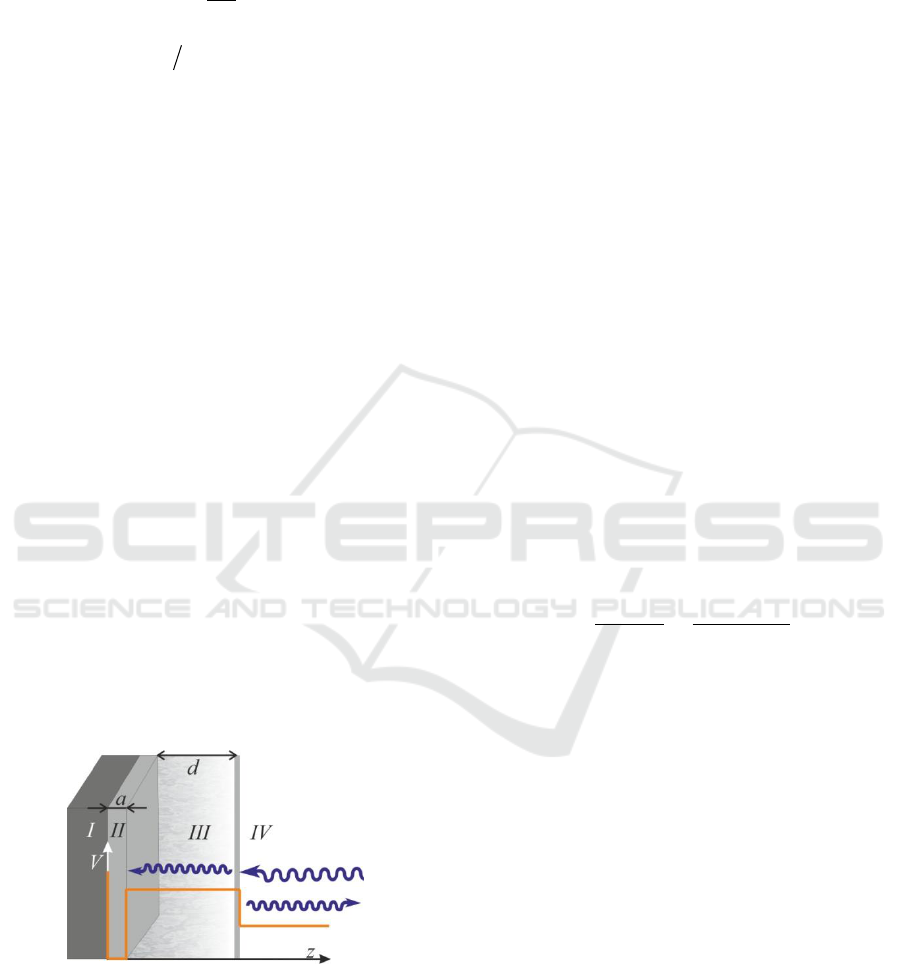
Figure 1: The concept of overcoming of radio
communication blackout: profile of the "potential barrier"
))(1()( zzV
containing a vehicle (antenna)
surface (I), dielectric layer (II) which covers the antenna
and plasma sheath (III). (IV) corresponds to the region of
infinite motion of the electromagnetic wave (atmospheric
air).
If energy of particles coincides with the position
of one of the energy levels in the well the tunneling
will have resonant character. This will result in
effective filling of the potential well by the particle
wave function. Then using the analogy between
optics and quantum theory we can state that if the
frequency of incident radiation coincides with the
eigen-frequency of resonator (dielectric layer) the
wave-field will penetrate through the plasma sheath
and fill the resonator even in the case when
p
.
In nonresonant case the wave field is rejected from
the plasma layer and filling is negligible.
3.1 Normal Incidence
We will start our consideration of overcoming the
radio communication blackout problem from the
case of normal incidence of the electromagnetic
wave on the hypersonic vehicle. Moving at
hypersonic speed through the Earth atmosphere it
creates around itself a layer of air plasma of
105 d
cm thickness with electron
concentration about
1110
1010~
e
n
cm
-3
(Nusca,
1997). For such values of concentration one obtains
10
1021~
p
s
-1
. If we take into account the
collisions of electrons plasma permittivity becomes
complex:
)(
1
22
2
22
2
pp
p
i
.
(7)
Here
is the transport frequency. For the gas
concentration
17
10N
cm
-3
(we consider the
atmospheric air at heights of several dozens of
kilometers) we assume that
9
10
s
-1
. Imaginary
part of permittivity leads to absorption of the
radiation in plasma. Similarly, the imaginary part of
potential function
)(zV
in quantum theory provides
the possibility to put in the absorption or birth of the
particles in the flux.
As it has been already noted to provide the
effective tunneling of electromagnetic wave through
the plasma barrier one should embed the dielectric
layer
d
between antenna and plasma sheath which
will act as a resonator. We assume that the plasma
layer is characterized by rectangular profile of the
electron density. Than in our calculations we have
the following permittivity profile:
PHOTOPTICS 2018 - 6th International Conference on Photonics, Optics and Laser Technology
150
daz
daza
az
z
air
p
d
,
,
0,
)(
.
(8)
Here
a
is the thickness of dielectric layer with
permittivity
d
,
1
air
is the permittivity of the
atmospheric air. Spectrum of standing waves in
dielectric layer is determined by
....3,2,1, nnak
n
, therefore resonant
frequencies are
n
a
c
d
n
.
(9)
For example, for dielectric layer with
1a
cm and
150
d
(this corresponds to novel ferroelectric
polymer composites (Dang et al, 2003) we obtain
9
1
107,7
s
-1
(
2.12
f
GHz). In
particular for
11
10
e
n
cm
-3
(
10
108.1~
p
s
-1
)
one obtains two stationary states in resonator (n
=1,2) for frequencies
pn
.
The solutions of wave equation (3) with
permittivity (8) in each spatial region are:
);exp()exp(:
),exp()exp(:
),sin(:
33
1
zikEzikEEIV
zEzEEIII
zkEEII
airair
pp
d
(10)
where
d
c
k
1
,
p
c
,
03
kk
,
air
E
is the given amplitude of the incident wave field,
p
E
and
d
E
are the amplitudes of wave field in
plasma and dielectric correspondingly.
Provided that the function (10) and its derivative
are regular at points of permittivity discontinuity we
obtain the results for the filling factor
)( fF
in
dependence on radiation frequency for given
dielectric layer parameters (fig. 2) which represents
the degree of resonator filling by the incoming
radiation flux:
22
max)(
aird
EEfF
.
(11)
where
2
d
E
and
2
air
E
are the squared absolute
values of electric field strength in the dielectric layer
and air correspondingly. The introduced filling
factor characterizes the effectiveness of the
interaction of antenna with incoming flux. We
would like to note that the filling factor can be even
greater than unity (see fig. 2a).
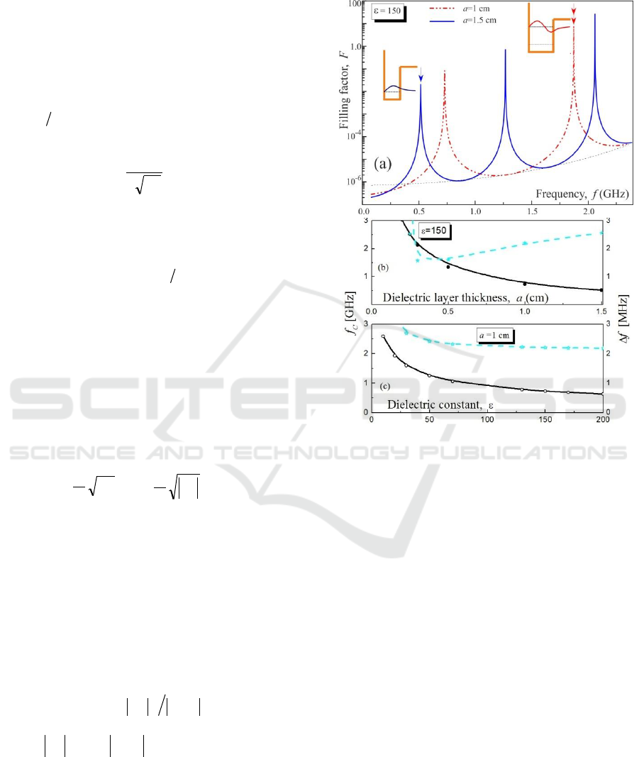
Figure 2: The filling factor
)( fF
in dependence on the
transmitted signal frequency (a) and the position of first
resonance and its FWHM in dependence on the dielectric
layer thickness (b) and dielectric constant (c). Calculations
are made for
10d
cm.
As it can be seen from fig. 2(a) the position and
number of resonances essentially depends on
thickness of dielectric layer: to shift the resonance to
the lower frequencies one should increase the width
of dielectric. There is the difference between
resonant frequencies obtained by expression (9) and
in numerical calculations which is related to the
finite height of the plasma barrier. To transfer
information to antenna through a plasma sheath, the
positions f
C
and the widths Δf of the transparency
peaks are of critical importance. Figure 2(b) presents
the resonant peaks behavior (the carrier frequency of
the order of 1 ... 2 GHz, the bandwidth of a few
MHz) in dependence on dielectric properties. It is
easy to see that tracking telemetry and command
(TT&C) signals in the presence of plasma sheath are
possible within the framework of our concept with
reasonable parameters of the resonator used.
Resonant Tunnelling and Optical-mechanical Analogy - Overcoming of Blackout Problem
151
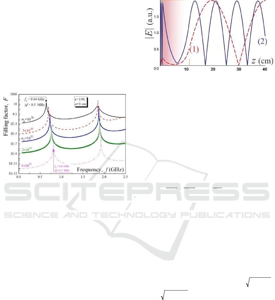
The dependence of filling factor on the electronic
density in the plasma layer is displayed at fig. 3. We
see that with the increase of
e
n
the position of
resonances slightly shifts towards higher values of
frequency, the limit value of this shifting is
determined by the expression (9), that corresponds
to the resonator with ideally conducted walls. Also
one should mention the decrease of the filling factor
value with increase of the electronic density both for
resonant and nonresonant tunneling. This fact results
from the decreasing of the tunnel transparency of the
plasma layer for higher electronic densities.
Figure 3: The filling factor
)( fF
in dependence on the
transmitted signal frequency for different values of
electronic density in the plasma layer.
To give more insight to the process of
electromagnetic field penetration through the plasma
sheath we perform the data for spatial distribution of
the absolute value of the electric field strength
corresponding for two lower resonances (fig. 4). The
resonant distribution corresponds to the frequencies
73.0
1
f
GHz, and
87.1
2
f
GHz.
3.2 Oblique Incidence
Here we are going to move up to the case of the
oblique incidence of the electromagnetic wave on
the above discussed structure. It is important to
notice that in this case one can distinguish two types
of electromagnetic waves: TE and TM. Let us
remind that in the TE wave vector
E
is
perpendicular to the plane of incidence (TE -
Transverse Electric) while in TM wave
E
belongs
to it (TM - Transverse Magnetic). Propagation of
these two waves through the potential structure
differs from each other.
Figure 4: Spatial distribution of the absolute value of the
electric field strength in resonant cases (the distribution is
normalized to the incoming flux). Curves (1) and (2)
correspond to the first and second eigen-frequencies of the
resonator. Calculations are performed for
1a
cm,
150
d
,
10d
cm,
11
10
e
n
cm
-3
.
Let us first consider the case of TE wave. Here
we suppose that the wave vector lies in the xz-plane,
is the angle of incidence of electromagnetic wave
counted off from the z-axis. In this case electric field
has the only tangential x - component, while for
magnetic field both y and z components are non-
zero. Then the wave equation for electric field reads:
0)(
2
2
2
2
2
2
E
c
z
z
E
x
E
.
(12)
One can write its solution in each spatial region
);exp(
)exp()exp(:
),exp(
)exp()exp(:
),exp()sin(:
3
33
2
22
11
xik
zikEzikEEIV
xik
zEzEEIII
xikzkEEII
x
zaza
x
zpzp
xzd
(13)
here due to the boundary conditions
sin
0321
kkkk
xxx
;
2
1
2
11 xz
kkk
,
2
2
2
2 xz
k
,
cos
03
kk
z
. The incoming
flux is normalized to unity. Boundary conditions
represent the continuity of the tangential
components of electric field and its derivative at the
interfaces.
The filling factor dependences (2
nd
resonance) on
the angle of incidence for TE wave are performed at
fig. 5. With the increase of the angle one can see
shifting of the peak to higher frequencies and
decreasing of its maximum value. The last
circumstance appears due to the decrease of the
normal component of the incoming electromagnetic
PHOTOPTICS 2018 - 6th International Conference on Photonics, Optics and Laser Technology
152
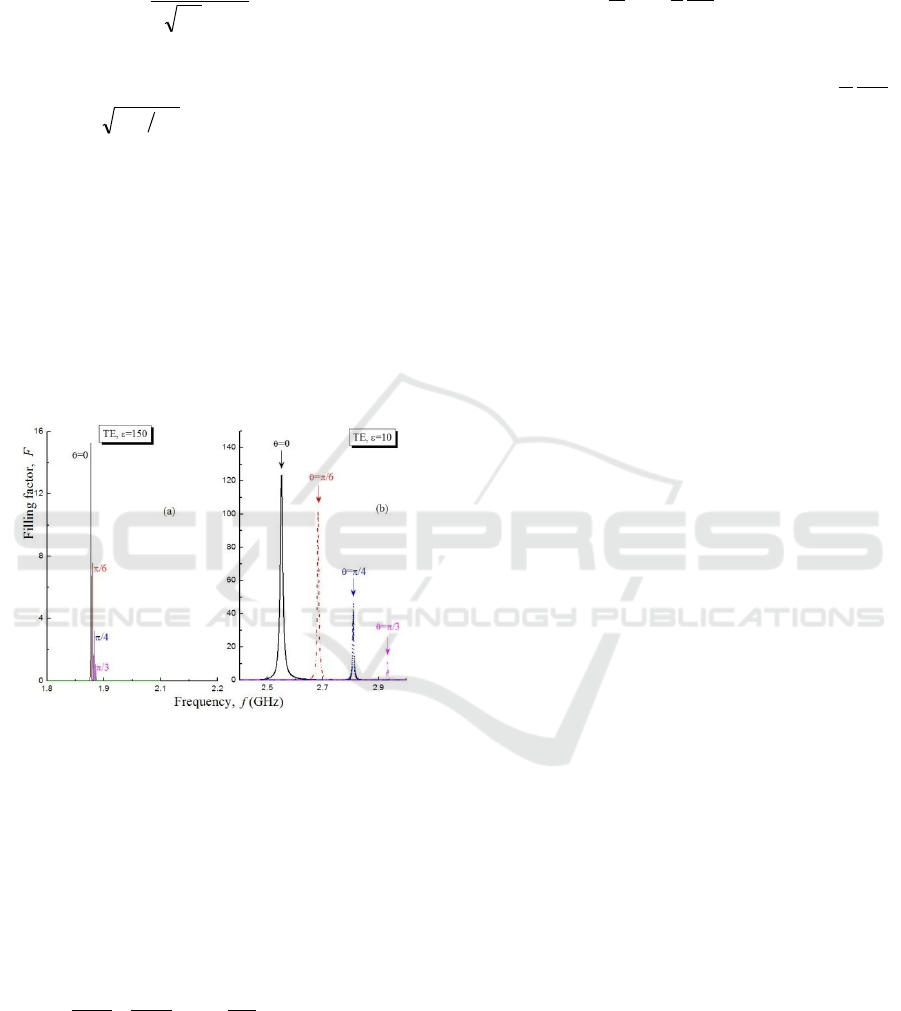
wave flux. Actually, in the case of oblique incidence
standing wave frequencies in dielectric layer are
n
a
c
d
n
cos
.
(14)
where
is angle of slope of electromagnetic wave
in dielectric layer measured from the z axis:
dair
sinsin
. As the result the more is the
angle of incidence the more is the resonance
shifting. In this case dielectric layer with high value
of permittivity plays the role of «stabilizer»
preventing significant displacement of resonant
peaks. To demonstrate this fact we present the filling
factor for two values of dielectric layer permittivity,
10
d
and
150
d
(see fig. 5). Actually, for
150
d
which is within the range of particular
interest for the problem of overcoming of the
communication blackout the resonance shifting is
negligible (fig. 5(a)).
Figure 5: Filling factor
)( fF
for the piecewise
continuous dielectric permittivity profile (7) for TE wave
in dependence on incidence angle. (a) corresponds to the
high value of dielectric constant
150
d
, (b) is for the
dielectric constant
10
d
. Plasma sheath parameters are
the same as at fig. 2.
For the TM wave magnetic field has only the
tangential x-component. Hence, it is handier to solve
the wave equation for the magnetic field:
.0)(
2
2
2
2
2
2
H
c
z
z
H
x
H
(15)
Provided that permittivity is piecewise continuous
function in space equation (15) is identical to eq.
(12). Thus the solutions for magnetic field in each
spatial region will be determined by expressions
similar to (13). The difference appears when writing
the condition for continuity of the tangential
component of field
E
:
.
1
z
H
E
c
i
x
(16)
It means that instead the continuity of
H
and its
derivative we have the continuity of
H
and
z
H
1
.
This circumstance leads to some peculiarities of the
process of TM wave propagation through the plasma
barrier: optical mechanical analogy will work only
for TE wave propagation, TM wave propagation is
beyond this analogy. Physical reason for this is
directly associated with the induced oscillations of
the plasma barrier resulting from the existence of z-
component of field E. We plan to study this
phenomenon in more detail in further publications.
Actually, the phenomenon of electromagnetic wave
tunnelling is more complicated that the quantum-
mechanical tunnelling due to the vector nature of the
electromagnetic field.
4 CONCLUSIONS
Thus, the new approach is proposed to overcome the
communication blackout during the hypersonic
vehicle movement through the Earth atmosphere.
The approach is based on the optical-mechanical
analogy which allows to consider plasma sheath
surrounding the vehicle as a potential barrier and
analyse the process of electromagnetic wave
tunnelling. It is demonstrated that dielectric layer
covering of the antenna surface can act as the
resonator providing resonance tunneling at definite
frequencies of the electromagnetic wave. Some
peculiarities of optical-mechanical analogy
applicability for the analysis of the radio frequency
wave tunnelling regime are studied. It is shown that
this analogy can be applied only for the case of TE
wave.
ACKNOWLEDGMENTS
This work was supported by the Russian Foundation
for Basic Research (projects no 15-02-00373, 16-32-
00123, 16-29-09515-ofi_m).
Resonant Tunnelling and Optical-mechanical Analogy - Overcoming of Blackout Problem
153

REFERENCES
Bobkov, N. A., Marchenko, V. F., Zakharova, I. G., et al.
2016. J. Commun. Technol. Electron., 61, 261.
Dang, Z.-M., Lin, Y.-H. and Nan, C.-W. 2003. Advanced
Materials, 15, 1625
Gao, Xiaotian and Jiang, Binhao. 2015. J. Appl. Phys.,
117, 233301
Gillman, E. D. and Foster, J. E. 2009. in IEEE
International Conference on Plasma Science, (IEEE,
2009), p. 1.
Hasbun, J. E. 2003. J. Phys.: Condens. Matter, 15, R143
Jung, J., and Keller, O. 2017. J. Opt. Soc. America A, 34,
726.
Kidun, O., Fominykh, N. and Berakdar, J. 2005. Phys.
Rev. A, 71, 022703.
Korotkevich, A. O., Newell, A. C. and Zakharov, V.E.
2007. J. Appl. Phys., 102, 083305.
Lei, S., Lei, Z., Bo, Y. and L. Xiaoping, L. 2015. Plasma
Sci. Technol., 17, 1006.
Li, W. 2016. Materials Research Express, 3, 126201.
Nazarenko, S., Newell, A. C. and Zakharov, V.E. 1994.
Phys. Plasmas, 1, 2834.
Narimanov, E. E. and Kildishev, A.V. 2009. Appl. Phys.
Lett., 95, 041106.
Nusca, M. 1997. J. Thermophys. Heat Transfer, 11, 304.
Razzaz, F. and Alkanhal, M. A. S. 2017. Scientific
Reports, 7, 41961.
Shi, L., Bai, B. W., Liu, Y. M. and Li, X. P. 2013. J.
Electromagn. Waves Appl., 27, 518.
Shvartsburg, A. B. 2007. Phys. Usp., 50, 37.
Wang, Zhi-jun, Guo, Li-xin and Li Jiang-ting 2016. 11th
International Symposium on Antennas, Propagation
and EM Theory (ISAPE), 882.
Xie, K., Yang, M. and Bai, B. 2016. J. Appl. Phys., 119,
023301
Yang, Y. P., Leng, L. Y., Wang, N., Ma, Y. G. and Ong,
C. K. 2012. J. Opt. Soc. America A, 29, 473.
PHOTOPTICS 2018 - 6th International Conference on Photonics, Optics and Laser Technology
154
