
Verlet with Collisions for Mass Spring Model Simulations
Maciej Kot
1
and Hiroshi Nagahashi
2
1
Imaging Science and Engineering Laboratory, Tokyo Institute of Technology, Tokyo, Japan
2
Laboratory for Future Interdisciplinary Research of Science and Technology, Tokyo Institute of Technology, Tokyo, Japan
Keywords:
Mass Spring Models, Deformable Objects, Collisions, Verlet, Friction.
Abstract:
In this paper we study the problem of the interaction of soft bodies modeled with mass spring models (MSM)
and static elements of the environment. We show that in such setup it is possible to couple standard time
evolution of MSMs with collision responses in a way, that does not require complex processing for multi
collision situations while successfully preventing object inter-penetration. Moreover we show how to achieve
similar energy dissipation for models with different resolutions when the friction is present.
1 INTRODUCTION
Mass spring models are a popular choice for the rep-
resentation of soft bodies in computer graphics and
virtual reality applications. For a long time they were
preferred over the finite element method (FEM) in
real time applications, as they tend to offer better
computational efficiency (although recent FEM im-
plementations are quite fast as well (Sin et al., 2013)),
but they are believed to be less accurate in terms of
physical plausibility (Nealen et al., 2006).
The accuracy of the description of an elastic object
is however not a problem in MSM representations.
The standard lattice based models used in physics,
mechanical engineering and other related fields offer
a description of elastic solids, which is as accurate as
the limitations of linear elasticity theory allow it to be
(Ostoja-Starzewski, 2002) (Ladd and Kinney, 1997)
(Kot et al., 2015).
The bigger problem, when creating an anima-
tion, is to carry out the time evolution of such mod-
els (which can be achieved in a number of ways,
both quasi-static or dynamic (Faure and Wien, 1998)
(Jakobsen, 2001) (Frenkel, 2002) (Steinhauser, 2008)
(Liu et al., 2013) (Press et al., 2007) (Levine et al.,
2014) (Bender et al., 2013) (Michels et al., 2014)).
The number of techniques used for this purpose in
computer graphics is very large, but it should be
noted, that many of them are either not physically
based or that the physical correctness does not hold
for certain aspects of the simulation by design.
In this work we use explicit Verlet integration
scheme in order to achieve a physically-based sim-
ulation and we show how to couple it with collision
responses. One of our goals is to design a collision
handling technique which preserves the energy of the
system (affects stability of the simulation), prevents
object penetration, and if the friction is present, obeys
the Newton’s law of dry friction. We achieve this goal
completely for collisions between MSM and static el-
ements of the environment and partially for MSM-
MSM collisions; in case of MSM-MSM collisions our
method does not preserve energy in certain situations,
which is the cost of assuring no object penetrations.
Potential disadvantage of explicit integrators
(such as the Verlet algorithm) is the necessity of using
variable time step to avoid instabilities when large ac-
celerations are present. They are however very useful
for the purpose of studying certain aspects of the sim-
ulation and dynamic evolution of MSMs. It should
be noted that for practical purposes, techniques which
add some mechanism of controlling energyof the sys-
tem are much more popular; examples include po-
sition based or shape matching algorithms (Bender
et al., 2013) (M¨uller et al., 2005).
2 COLLISIONS
Defining a representation of a deformable object is
only half of the solution needed for performing a re-
alistic animation. Once we have the representation of
an object, we have to simulate its evolution in time,
which includes both evolution of its shape, as well as
its interaction with the environment, that is – colli-
sions with other objects.
314
Kot M. and Nagahashi H.
Verlet with Collisions for Mass Spring Model Simulations.
DOI: 10.5220/0006269303140320
In Proceedings of the 12th International Joint Conference on Computer Vision, Imaging and Computer Graphics Theory and Applications (VISIGRAPP 2017), pages 314-320
ISBN: 978-989-758-224-0
Copyright
c
2017 by SCITEPRESS – Science and Technology Publications, Lda. All rights reserved

2.1 Verlet Integration Scheme
The time integration algorithm which we use is con-
structed as a Verlet scheme following the Trotter
expansion (Ladd, 2010; Tuckerman et al., 1992;
Frenkel, 2002):
e
A+B
= lim
P→∞
(e
A/2P
e
B/P
e
A/2P
)
P
, (1)
where e
A+B
is understood to be an operator which
is advancing the state of the system by making P steps
of ”size” 1/P. A and B symbolise two quantities
which influence each other and need to be updated
”simultaneously”. If P is finite, the equation is ap-
proximate. In an MSM simulation, the two qualities
that characterise our system are positions q and veloc-
ities v (defined for each mass point), and the system
advances in time (i.e. from 0 to t) with steps dt.
The Eq. (1) can be translated into the following
algorithm:
1. advance positions by 0.5dt; (q += v· 0.5dt)
2. compute forces F
3. advance velocities by dt; (v += F/m· dt)
4. advance positions by 0.5dt,
which is known as a position Verlet integration
scheme. It can be used to simulate the time evolu-
tion of a mass spring system. It does not account for
collisions, as all the forces in the system come from
springs or gravity. Consequently collision handling
requires the algorithm to be extended.
2.2 Elastic Collisions
In our approach the collision of an object represented
by an MSM is carried out by colliding mass points of
the MSM, that is, through microcollisions. Detection
of collisions between MSM and meshes or objects
with well defined surfaces is straightforward. Colli-
sions between different MSMs as well as self colli-
sions require defining the surface of an MSM in some
way. In this work, we associate a collision sphere with
each mass point lying on the border of an object; the
radius of the sphere is equal to the average of the half-
length of springs connected to the node in question.
Additionally we assume that if two spheres are con-
nected by a spring they never produce a collision.
Each microcollision should preserve energy and
momentum of the system, that is for any two colliding
mass points (spheres) m
1
and m
2
moving with veloci-
ties v
1
and v
2
we have:
m
1
¯v
1
+ m
2
¯v
2
= m
1
¯v
1
′
+ m
2
¯v
2
′
m
1
¯v
2
1
+ m
2
¯v
2
2
= m
1
¯v
2
1
′
+ m
2
¯v
2
2
′
,
(2)
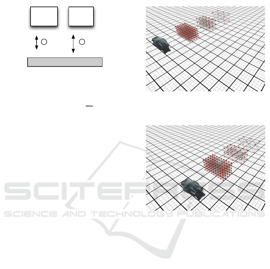
Figure 1: A symbolic illustration of multi-collision situ-
ation, where serial processing of collisions leads to high
number of collision events.
which gives new velocities as:
¯v
1
′
=
2m
2
¯v
2
+ (m
1
− m
2
) ¯v
1
m
1
+ m
2
¯v
2
′
=
2m
1
¯v
1
+ (m
2
− m
1
) ¯v
2
m
1
+ m
2
.
(3)
Non movable objects (such as a ground) are
treated as having infinite mass.
A computationally efficient way of handling col-
lisions is to process them in a serial way, as if none
two happened at the exact same moment. However,
the time resolution of our simulation is defined by
the time step, and it is not desirable for it to be too
small. This leads to multi-collisions, that is, situations
in which an object is colliding with multiple other ob-
jects during one time frame. If we detect collisions
once per frame, serial collision handling may lead to
objects penetrating each other (i.e. imagine a sphere
in between two planes with π/6 angle between them).
Increasing the number of detection/handling events
per time frame is not a solution, as it may lead to
significantly increased computational costs per frame
in some situations. Figure 10 symbolically illustrates
such situation. A ball reflected by one wall immedi-
ately hits the other wall, and reflected by it hits the
first wall once again making very little progress out-
side of this computational trap. On the other hand
performing only one collision per frame leads to ob-
ject penetration. The solution to this situation may
be to abandon serial collision handling, and instead
solve all the collisions simultaneously (e.g. as a con-
straint reaction problem). The disadvantage of such
technique is again the increased computational cost.
Below we will show how to prevent object pene-
tration while processing collisions in a serial way.
First of all, before we proceed to multi collision
problem, let us show how to achieve a stable simu-
lation for a simple setup of a ball bouncing on the
ground in gravitational field. Our time integration al-
gorithm consists of two conceptual parts – position
update and velocity update. Collision reaction can be
added as a third part, and by applying eq. (1) recur-
Verlet with Collisions for Mass Spring Model Simulations
315

sively, we arrive at one of possible algorithms:
1. advance positions by 0.5dt
2. compute forces
3. advance velocities by 0.5dt
4. handle collisions and friction by updating veloci-
ties (not forces)
5. advance velocities by 0.5dt
6. advance positions by 0.5dt
This scheme will produce energy preserving sim-
ulations which are stable over long time scales, and
will work if the bouncing mass is receiving forces
from springs as well. First we advance positions (half
step), then velocities, which by itself consists of two
steps – applying force influence and collisions. Note,
that collision handling procedure uses the values of
velocities in the middle of the frame (at the half step).
It is a popular approach of incorporating collision re-
sponse into the simulation used e.g. in (Bridson et al.,
2002).
This algorithm, if collision handling is processed
in a serial way, may produce object overlaps if a
single mass point of the MSM is colliding with
multiple independent objects. It should be noted,
that for volumetric MSMs this is unlikely to happen
unless the object’s curvature is high. Consequently
this algorithm could be used for volumetric MSMs
in low curvature environments. Unfortunately the
behavior of clothes would be affected considerably,
as 2d objects stacked together produce exactly this
kind of multi-direction multi-collisions, which cause
overlaps. Because of that, the algorithm typically
requires additional constraint solving procedure of
some kind (Atencio et al., 2005).
2.3 Elastic Collisions with Overlap
Prevention
For the purpose of preventing object overlaps, we
modify the algorithm in the following way:
1. advance positions by 0.5dt
2. apply half of the collision/friction response
3. compute forces
4. advance velocities by dt
5. compute collision/friction response
6. apply half of the collision/friction response
7. advance positions by 0.5dt
The collision response was switched with veloc-
ity update when compared to the previous algorithm.
The second step uses collision/friction response infor-
mation from the ”previous” frame (although we may
very well say that each frame starts at the step 4, and
the whole procedure will look more natural). Steps 2
and 6 (apply c/f response) modify velocities.
In a perfectly elastic collision of two hard objects
(eq. (3)), the state in which half of the response is ap-
plied results with a situation where normal component
of the relative velocity between these two colliding
objects equals zero. Therefore steps 7 and 1 are guar-
anteed not to produce any additional overlap between
them. This means, that if an MSM node collides with
multiple elements of static environment (i.e. triangles
of an unmovable mesh), the node will remain at rest
state relative to these static elements (in terms of nor-
mal velocities).
If there are additional MSM nodes colliding with
each other they too, can be brought together to the
state of the same relative velocity, however it may re-
quire applying collision response to them, with differ-
ent proportions than those present in steps 2 and 6 (i.e.
instead half-half, we may need to do e.g. 0.3 and 0.7
response). In such situations energy preservation is
no longer guaranteed (with energy differences of the
same magnitude as those present e.g. in Verlet with
adaptive time-step).
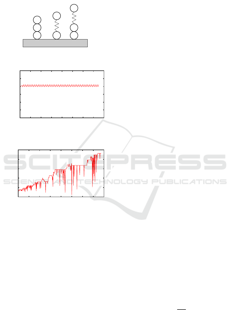
The effects of this can be seen in Figs. 3 and 4.
The Figure 3 shows an energy of a system, where
3 MSM nodes lie on top of each other (and on the
ground, Fig. 2 A). There is no energy drift present.
Also, there is no drift if the node colliding with the
ground is connected by a spring with the rest of the
MSM. We observe however a small drift if there is
a second node present between the ground and the
spring node (Fig. 2 C). The Figure 4 shows an energy
of such system. In both cases the bottom node under-
goes a constant collision with a ground and the node
above. If spring forces are present, there is a notice-
able energy drift in the system, however as its mag-
nitude is rather small, its effects will be completely
eliminated if friction and damping effects are incor-
porated into the simulation.
3 CONTACT FRICTION
The problem of collisions with frictional contact has
been studied previously for various model represen-
tations and time integration schemes (Fisher and Lin,
2001) (Hasegawa and Sato, 2004) (Cotin et al., 1998)
(James and Pai, 2002) (Duriez et al., 2006) (Pabst
et al., 2009), and the common approaches include,
GRAPP 2017 - International Conference on Computer Graphics Theory and Applications
316
A
C
B
Figure 2: Three example configurations of collisions be-
tween MSM nodes and the ground.
11
11.05
11.1
11.15
11.2
11.25
11.3
0 2 4 6 8 10 12 14 16
Energy
Time
Figure 3: Energy of the system in a typical multi collision
situation (such as the one on Fig.2 A).
9.7
9.75
9.8
9.85
9.9
9.95
0 5 10 15 20 25 30 35 40
Energy
Time
Figure 4: Energy drift present in a multi collision setup,
when multiple objects are stacked on each other and spring
connections are present (setup form Fig. 2 C).
among others, constraint based methods and penalty
force methods (Michels et al., 2014). In the context of
mass spring models, the focus has been placed on 2d
meshes designed for a cloth representation (Bridson
et al., 2002) (Pabst et al., 2009). While such methods
have a good potential to be extended to volumetric ob-
jects, the existing works lack argumentation and con-
vincing testing schemes that would verify their phys-
ical correctness.
The Newton dry friction model assumes that:
• Friction force is proportional to the normal pres-
sure between contacting objects and is parallel to
the contact surface
• It does not depend on the area of contact between
objects
• It does not depend on the velocity of sliding sur-
faces
Let us consider a volumetric object sliding on a
flat surface with friction. The friction force will be
proportional to the gravitational force acting on the
object:
F = µF
g
= µ· M· g, (4)
where µ is the friction coefficient (which in
general will depend on both colliding surfaces),
M is the mass of the moving object and g denotes
gravitational acceleration coefficient.
In rigid body dynamics, the mass of the whole
object has to be known for the friction force to
be calculated correctly. In our case however all
the interactions between the surface and the object
happen through a handful of boundary mass points
that collide with the surface and the frictional force
should be applied only to those points. For the sake
of efficiency the friction handling algorithm should
not require the knowledge about any other nodes of
the colliding MSM or MSM stacked on top of it.
Consequently the equation 4 is not really usable.
Instead its properties should be recreated by simple
rules for single mass point collisions.
Fortunately these rules are very easy to find and
understand (Kot and Nagahashi, 2014). Let us con-
sider a box sliding on a flat surface. We will represent
it by MSMs with three different resolutions (Fig. 6).
The first box – 3× 2× 2 mass points, the second by
5× 3 × 3 lattice and the third – 9× 5 × 5. The total
mass of each box is the same, therefore elementary
masses of the MSM nodes will differ. Also the
number of the nodes colliding with the surface will
be different: 6 mass points for the low resolution
MSM, 15 for medium and 45 for high. This con-
stitutes 50%, 33% and 20% of the total number of
nodes for each model respectively. Consequently the
number of elementary collisions will differ greatly
between these models, and each elementary collision
will result in a different elementary momentum
flow between object and the surface. Moreover for
each point the frequency of collision events will
differ. What will be invariant between high, medium
and low resolution representations however, is the
total flow of momentum that passes from the object
through the colliding surface.If we consider, that each
mass point m
i
represents some elemental volume and
consequently elemental area of contact a
i
, bounces
of the surface with average frequency f
i
, changing is
momentum by ∆p
i
with each bounce (according to
eq. (3)), giving a flux j
i
=
∆p
i
f
i
a
i
, the total momentum
flow must sum up to Mg, because it is the condition
of objects not penetrating each other:
Verlet with Collisions for Mass Spring Model Simulations
317
v
2v
M 2M
Figure 5: Transfer of momentum between the ground and a
heavy object. Small particle bounces back and forth and the
heavy object never touches the ground.
j · A =
C
∑
i
j
i
a
i
=
C
∑
i
f
i
∆p
i
=
∆p
∆t
= Mg. (5)
The only quantity that we control directly when
giving a response to an elementary collision is ∆p
i
,
however we know, that all the other quantities will ad-
just themselves in such way, that the eq. (5) will hold
(i.e. if we decrease ∆p
i
, the frequency f
i
will increase
so that the momentum flow will remain constant).
This can be better understood with an illustration on
Fig. 5. A small particle bounces back and forth be-
tween the ground and a heavy object. If we increase
the mass of the object, the velocity of the particle will
increase automatically (increasing the frequency with
which it hits the ground). If we reduce the mass of the
small particle similar thing will happen. In the end,
the heavy object will never actually hit the ground in-
dependently on what we do with the small particle as
long as it transfers any momentum with each bounce.
Therefore if we associate with each collision an el-
ementary friction impulse F
i
= µ∆p
i
, the total fric-
tional force exerted on an object will accumulate to
F = µMg, independently on quantities such as A, f
i
and even ∆p
i
. The latter means that incorporating non
elastic collisions will not affect frictional force during
continuous contact of surfaces.
4 TESTS
In order to confirm that such micro collision approach
to friction allows to achieve a correct macroscopic re-
sponse we have performed a series of experiments
in which elastic objects slide with friction on a flat
surface. According to Newton’s dry friction law the
distance which each object travels before completely
stopping should be independent on the mass of the
object, its shape or apparent area of contact. We have
performed the test for various shapes – from simple
boxes to complex objects with non trivial shapes. Our
tests indicate that travel distance does not depend on
Figure 6: Four elastic objects sliding with friction on a flat
surface. Initial position. Three resolutions of a box (high,
medium, low), and a bird. Boxes have the same mass. Bird
has different mass and non flat surface.
Figure 7: Final position of the objects from Fig. 6.
the resolution of MSM, mass of the object or even its
shape, thus confirming that our method gives physi-
cally correct results.
Figures 6 and 7 show the initial and final positions
of four elastic objects. The three boxes represented
by different resolution MSMs travel exactly the same
distance before stopping, which shows that energy
dissipation rate is invariant with the resolution and
depends only on the friction coefficient. The fourth
object – a bird with non trivial shape and different
mass, slides beside the boxes. At the beginning only
its tail touches the ground (Fig. 8); soon due to grav-
itational force the rest of its body descends and the
area of contact with the ground is increased. Even
though the bird’s movement is complex and includes
shape relaxation with various vibrational modes, the
total distance that it travels is the same as in the case
of boxes.
GRAPP 2017 - International Conference on Computer Graphics Theory and Applications
318
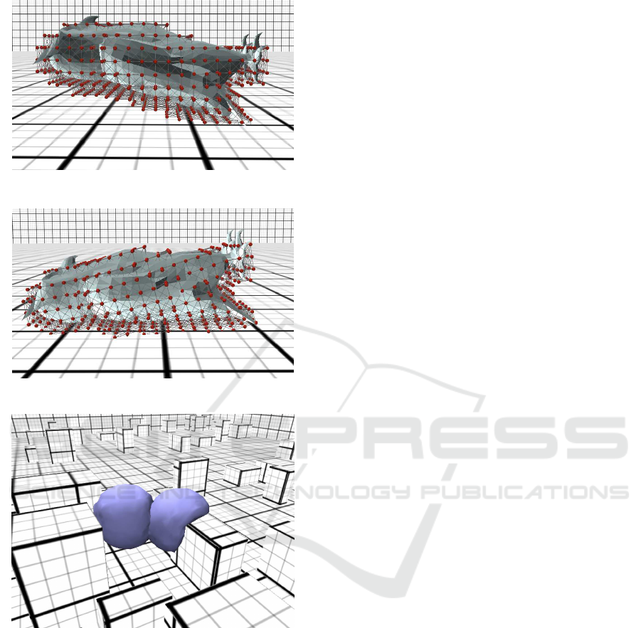
Figure 8: Initial position of the model of a bird.
Figure 9: Final position of the model of a bird.
Figure 10: Two spherical objects colliding with each other
and with the environment.
5 CONCLUSIONS
In this work we have shown tests of general behavior
of MSMs that involve collisions and friction in Ver-
let simulation. We demonstrate, that by rearranging
the order in which certain steps in Verlet scheme are
handled, and by splitting the collision response into
two steps, we can eliminate the need for any addi-
tional solvers. This can result in much simplified and
lightweight simulation system, which still produces
physically plausible animations. The presented tech-
nique is interesting both from academic and practical
point of view, is very robust, and will work satisfac-
tory for various conditions and situations.
Moreover we show, that total frictional force does
not depend on a single microcollision response, but
all the responses summed together. This means, that
careful analysis of singular microcollisions is unnec-
essary and does not affect the final result of the total
frictional force. Such analysis is often present in col-
lision responses in CG, and require e.g. measuring
penetration depth (Heidelberger et al., 2004), which
may increase costs of the collision response computa-
tion.
In our approach the frictional force acting on an
object does not change even if the area of contact or
the resolution of an MSM differs. Because the re-
sponse to each micro collision is local, the presented
algorithm will also work in case of multiple objects
stacked on each other. Lastly, the presented technique
has a very high computational efficiency, as it does
not require any knowledge about global properties of
colliding objects.
Dividing the collision response into two steps al-
lows to prevent progressing penetration of colliding
objects in serial collision handling. This approach
however has a limitation which manifests itself when
groupsof MSM nodes collide with each other. In such
cases, the energy of the system may change slightly
during the collision response. However for volumet-
ric MSM such situations occur very rarely, and only
for the models with high surface curvature (for an-
gles sharper than 90 degrees). In such cases our algo-
rithm behaves similarly to standard methods of col-
lision handling for MSMs (e.g. such as the method
described in (Jakobsen, 2001)). Although in friction-
less setup this may lead to noticeable energy drifts
over long periods of time, such methods has proven
to be suitable for wide range of practical applications.
If friction or damping are present the problem com-
pletely disappears because the energy dissipation due
to these phenomena is of much higher magnitude,
than the one caused by numerical inaccuracies.
REFERENCES
Atencio, Y. P., Esperanca, C., Cavalcanti, P. R., and
Oliveira, A. (2005). A collision detection and re-
sponse scheme for simplified physically based ani-
mation. In XVIII Brazilian Symposium on Computer
Graphics and Image Processing (SIBGRAPI’05),
pages 291–298.
Bender, J., M¨uller, M., Otaduy, M. A., and Teschner, M.
(2013). Position-based methods for the simulation of
solid objects in computer graphics. In EUROGRAPH-
Verlet with Collisions for Mass Spring Model Simulations
319

ICS 2013 State of the Art Reports. Eurographics As-
sociation.
Bridson, R., Fedkiw, R., and Anderson, J. (2002). Robust
treatment of collisions, contact and friction for cloth
animation. ACM Trans. Graph., 21(3):594–603.
Cotin, S., Delingette, H., and Ayache, N. (1998). Efficient
Linear Elastic Models of Soft Tissues for Real-time
Surgery Simulation. Technical Report RR-3510, IN-
RIA.
Duriez, C., Member, S., Dubois, F., Kheddar, A., and An-
driot, C. (2006). Realistic haptic rendering of interact-
ing deformable objects in virtual environments. IEEE
Transactions on Visualization and Computer Graph-
ics, 12:36–47.
Faure, F. and Wien, T. U. (1998). Interactive solid anima-
tion using linearized displacement constraints. In 9 th
Eurographics Workshop on Computer Animation and
Simulation. e.
Fisher, S. and Lin, M. C. (2001). Deformed distance fields
for simulation of non-penetrating flexible bodies. In
Proceedings of the Eurographic Workshop on Com-
puter Animation and Simulation, pages 99–111, New
York, NY, USA. Springer-Verlag New York, Inc.
Frenkel, D. (2002). Understanding Molecular Simulation -
From Algorithms to Applications. Academic Press.
Hasegawa, S. and Sato, M. (2004). Real-time rigid body
simulation for haptic interactions based on contact
volume of polygonal objects. Comput. Graph. Forum,
23(3):529–538.
Heidelberger, B., Teschner, M., Keiser, R., M¨uller, M., and
Gross, M. (2004). Consistent penetration depth esti-
mation for deformable collision response. In In Pro-
ceedings of Vision, Modeling, Visualization VMV’04,
pages 339–346.
Jakobsen, T. (2001). Advanced character physics. In
IN PROCEEDINGS OF THE GAME DEVELOPERS
CONFERENCE 2001, page 19.
James, D. L. and Pai, D. K. (2002). Real time simulation of
multizone elastokinematic models. In In Proceedings
of the IEEE International Conference on Robotics and
Automation, pages 927–932.
Kot, M. and Nagahashi, H. (2014). Collision response
in mass spring model simulations. Technical re-
port of IEICE. Multimedia and virtual environment,
113(470):287–290.
Kot, M., Nagahashi, H., and Szymczak, P. (2015). Elas-
tic moduli of simple mass spring models. The Visual
Computer, 31(10):1339–1350.
Ladd, A. J. C. (2010). Numerical methods for molecular
and continuum dynamics. 3rd Warsaw School of Sta-
tistical Physics, B. Cichocki, M. Napiorkowski, J. Pi-
asecki, eds., Warsaw Univesity Press, Warsaw.
Ladd, A. J. C. and Kinney, J. H. (1997). Elastic constants
of cellular structures. Physica A: Statistical and The-
oretical Physics, 240(1-2):349–360.
Levine, J. A., Bargteil, A. W., Corsi, C., Tessendorf, J.,
and Geist, R. (2014). A peridynamic perspective on
spring-mass fracture. In Proceedings of the ACM SIG-
GRAPH/Eurographics Symposium on Computer Ani-
mation.
Liu, T., Bargteil, A. W., O’Brien, J. F., and Kavan, L.
(2013). Fast simulation of mass-spring systems. ACM
Transactions on Graphics, 32(6):209:1–7. Proceed-
ings of ACM SIGGRAPH Asia 2013, Hong Kong.
Michels, D. L., Sobottka, G. A., and Weber, A. G. (2014).
Exponential integrators for stiff elastodynamic prob-
lems. ACM Trans. Graph., 33(1):7:1–7:20.
M¨uller, M., Heidelberger, B., Teschner, M., and Gross, M.
(2005). Meshless deformations based on shape match-
ing. ACM Trans. Graph., 24:471–478.
Nealen, A., M¨uller, M., Keiser, R., Boxerman, E., Carl-
son, M., and Ageia, N. (2006). Physically based
deformable models in computer graphics. Comput.
Graph. Forum, 25(4):809–836.
Ostoja-Starzewski, M. (2002). Lattice models in microme-
chanics. Applied Mechanics Reviews, 55(1):35–60.
Pabst, S., Thomaszewski, B., and Strasser, W. (2009).
Anisotropic friction for deformable surfaces and
solids. In Proceedings of the 2009 ACM SIG-
GRAPH/Eurographics Symposium on Computer An-
imation, SCA ’09, pages 149–154, New York, NY,
USA. ACM.
Press, W. H., Teukolsky, S. A., Vetterling, W. T., and Flan-
nery, B. P. (2007). Numerical Recipes 3rd Edition:
The Art of Scientific Computing. Cambridge Univer-
sity Press, New York, NY, USA, 3 edition.
Sin, F., Schroeder, D., and Barbic, J. (2013). Vega: Non-
linear fem deformable object simulator. Comput.
Graph. Forum, 32(1):36–48.
Steinhauser, M. O. (2008). Computational Multiscale Mod-
eling of Fluids and solids. Springer-Verlag Berlin Hei-
delberg.
Tuckerman, M., Berne, B. J., and Martyna, G. J. (1992). Re-
versible multiple time scale molecular dynamics. The
Journal of Chemical Physics, 97(3):1990–2001.
GRAPP 2017 - International Conference on Computer Graphics Theory and Applications
320
