A Virtual Glove System for the Hand Rehabilitation based on Two
Orthogonal LEAP Motion Controllers
Giuseppe Placidi
1
, Luigi Cinque
2
, Andrea Petracca
1
, Matteo Polsinelli
1
and Matteo Spezialetti
1
1
A
2
VILab, Department of Life, Health & Environmental Sciences, University of L’Aquila, Via Vetoio, L’Aquila, Italy
2
Department of Computer Science, Sapienza University, Via Salaria, Rome, Italy
giuseppe.placidi@univaq.it, cinque@di.uniroma1.it, andrea.petracca@graduate.univaq.it,
matteo.polsinelli@student.univaq.it, matteo.spezialetti@graduate.univaq.it
Keywords:
Hand Rehabilitation, Virtual Glove, LEAP Motion Controller.
Abstract:
Hand rehabilitation therapy is fundamental in the recovery process for patients suffering from post-stroke or
post-surgery impairments. Traditional approaches require the presence of therapist during the sessions, in-
volving high costs and subjective measurements of the patients’ abilities and progresses. Recently, several
alternative approaches have been proposed. Mechanical devices are often expensive, cumbersome and patient
specific, while virtual devices are not subject to this limitations, but, especially if based on a single sensor,
could suffer from occlusions. In this paper a novel multi-sensor approach, based on the simultaneous use
of two LEAP motion controllers, is proposed. The hardware and software design is illustrated and the mea-
surements error induced by the mutual infrared interference is discussed. Finally, a calibration procedure, a
tracking model prototype based on the sensors turnover and preliminary experimental results are presented.
1 INTRODUCTION
The hand is a fundamental organ of the human body
and fulfill several complex tasks corresponding to a
deep brain involvement. For patients suffering from
post-stroke or post-surgery residual impairments the
recovery of the hand functions is extremely impor-
tant for accelerating the rehabilitation process. The
possibility of the recovery is strictly related to the fre-
quency, the duration and the quality of the rehabilita-
tion sessions (Kopp et al., 1999; Liepert et al., 2000;
Hallett, 2001; Arya et al., 2011). In the traditional re-
habilitation approach, a therapist is required to follow
the patient during one-to-one expensive sessions and
subjective evaluations (the therapist, basing on his ex-
perience, evaluates the results). Over the last years,
several automated (tele)rehabilitation tools, based on
mechanic or virtual devices have been presented, in
order to allow patients to execute the therapy in a
domestic environment being followed by therapists
through Internet (Burgar et al., 2000; Kahn et al.,
2006; Placidi, 2007; Franchi et al., 2009; Franchi
et al., 2010; Zimmerli et al., 2013; Placidi et al., 2013;
Llor
´
ens et al., 2015).
Mechanical approaches usually involve the em-
ployment of gloves equipped with pressure sensors
and pneumatic actuators for assisting and monitoring
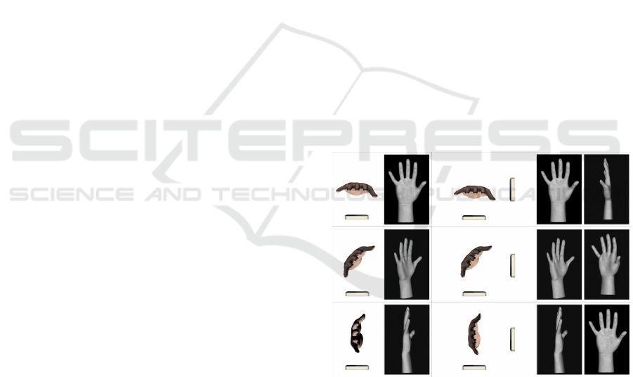
Figure 1: System based on a single LEAP sensor (left panel)
and based on two orthogonal LEAP sensors (right panel).
The view shown in the third row is occluded for a single
LEAP and not for a double configuration.
the hand movements and to apply forces to which the
fingers have to oppose (Lum et al., 2012; Maciejasz
et al., 2014). Despite the measurement accuracy they
are capable to achieve, these systems are expensive,
cumbersome (they limit the patients spontaneity and
freedom of movements) and patient specific (limiting
the possibility of reusing). For replacing mechanical
components, existing virtual approaches are based on
184
Placidi, G., Cinque, L., Petracca, A., Polsinelli, M. and Spezialetti, M.
A Virtual Glove System for the Hand Rehabilitation based on Two Orthogonal LEAP Motion Controllers.
DOI: 10.5220/0006197801840192
In Proceedings of the 6th International Conference on Pattern Recognition Applications and Methods (ICPRAM 2017), pages 184-192
ISBN: 978-989-758-222-6
Copyright
c
2017 by SCITEPRESS – Science and Technology Publications, Lda. All rights reserved
evaluation of videos from RGB or depth sensing cam-
eras to calculate hand kinematic information in real
time, (Rus
`
ak et al., 2011; Avola et al., 2013; Chaud-
hary et al., 2013; Placidi et al., 2014; Charles et al.,
2014; Placidi et al., 2015).
The LEAP motion controller
(http://www.leapmotion.com, 2016) is a recently
presented low-cost and non-bulky hand tracking
device, characterized by high-resolution and high-
reactivity (Bachmann et al., 2015) and represents a
good system to be used for virtual reality applications
and rehabilitation (Petracca et al., 2015; Polsinelli,
2015). It is a stereo vision device composed by 3
LED sources and 2 infrared cameras, that suffers the
limitations of a monocular system being unable to
recognize every position of the hand (occlusions can
frequently occur). In order to address the occlusions
issue, in this work a multi-sensor approach based on
the use of two orthogonal LEAPs is proposed. The
rest of the paper is organized as follows: Section
2 describes the proposed strategy, by showing the
hardware structure (2.1), the software architecture
(2.2) and the evaluation of the infrared interferences
when using two sensors (2.3); Section 3 shows the
tracking model prototype and some hand tracking
preliminary results (3.3).
2 MATERIALS AND METHODS
The system has been designed to obtain simultaneous
information from two LEAPs, orthogonally placed
each other. The reason is that a single LEAP sensor is
Figure 2: (a) The LEAP sensor and its references system.
(b) Hardware configuration with two orthogonal LEAPs has
been designed in order to create a wide area in which the
hand can be tracked.
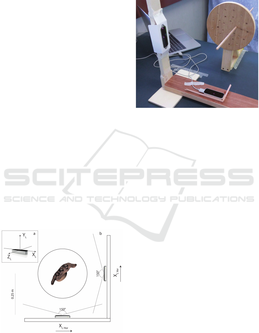
Figure 3: Experimental setup of the orthogonal LEAPs and
the tool used to calibrate the system.
not able to compute with accuracy the hand position
if the palm (and the fingers) is not visible, that is if the
vector orthogonal to the palm is approximately paral-
lel to the sensor plane (see Figure 1 third row). Using
two orthogonal sensors should ensure that at least one
of them is able to get the correct position. One of the
major issues to be addressed was the devices connec-
tion: the driver and the API are not able to manage
multiple instances of the LEAP on the same machine.
For this reason an architecture including a virtual ma-
chine has been designed. Moreover, in order to build
a consistent hand model using information from both
sensors, their reciprocal position had to be computed
with high accuracy through a calibration procedure.
2.1 Hardware Setup
A LEAP Motion Controller is a small device, de-
signed to be placed above the surface of a desk. It
can be connected to the PC through a USB port. The
hardware includes two monochromatic infrared cam-
eras and three LEDs emitting static IR beams (wave-
length 850 nm). Considered the 3-Dimensional ref-
erence system used by the LEAP to represent the ob-
jects, shown in Figure 2.a, the fields of view of the
sensor is 150
◦
along the X axis and 120
◦
along the
Z axis. The intensity of the emitted light, limited by
the power supplied by the USB port, allows to ob-
serve an object within a distance of about 0.6 m from
the sensor. Objects in the field of view of the LEAP
are enlightened by the LEDs and the reflected light is
captured by the cameras, producing a couple of grey-
scale images that are used, at software level, to iden-
tify the objects positions, thanks to a stereo vision al-
gorithm (Weichert et al., 2013). The sensor is able
A Virtual Glove System for the Hand Rehabilitation based on Two Orthogonal LEAP Motion Controllers
185
to track up to two hands simultaneously, by using a
3D model of the hand that includes the positions of
the fingers joints, but can also recognize objects like
sticks and pencils. In this work, two LEAPs have been
fixed to a support, in such a way as to be orthonormal
and distant 0.25 m from the center of the scene, in or-
der to create a wide area in which the hand can freely
move and can be tracked by both sensors (Figure 2.b
and Figure 3).
2.2 Software Architecture
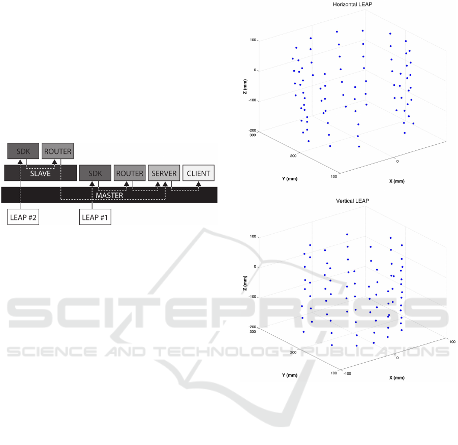
Figure 4: The software architecture: a virtual machine
(Slave) has been installed on the physical machine (Mas-
ter), for assigning each of the connected sensors to a dif-
ferent SDK; a javascript router was used to carry data from
both LEAPs to a single server.
LEAP is equipped with an SDK that allows to the
communication with the sensor both through a na-
tive and a web-socket based interface. By using the
latter it is possible to obtain a JSON data structure
containing tracking data (for more details, please re-
fer to (http://developer.leapmotion.com, 2016)). Un-
fortunately, the SDK does not allow the creation of
more than one instance of the device on a single ma-
chine. In order to address this issue, a virtual ma-
chine had to be included in the software setup (Figure
4 shows the diagram of the architecture). The vir-
tual machine (Slave) has been installed on the physi-
cal machine (Master): in this way, plugging both sen-
sors, one of them has been assigned to Master and the
other to Slave allowing to the machines to instanti-
ate their own driver. On each machine, data provided
by the SDK through the websocket (the port number
was fixed) were captured by a javascript router (ex-
ecuted on an instance of Node.js (http://nodejs.org,
2016)) and rerouted towards a Node.js server (hosted
on the Master machine). In this way, using again web-
sockets, the server was able to send data of both de-
vices to one or more clients running on Master.
2.3 Infrared Interferences Evaluation
The described setup has been used to evaluate the in-
frared interferences that the sensors could cause each
other. The main idea was to record the position of
Figure 5: The positions of the tested points seen from the
horizontal LEAP (up) and from the vertical LEAP (down)
each represented with its own reference system.
the same set of points (by tracking the tip of a stick,
see Figure 3), using both sensors, in different condi-
tions: just the LEAP used for the measure switched
on; both LEAPs switched on. The first case repre-
sented what we defined the “ideal condition” used for
estimating the “positioning error” (it contained just
the error intrinsic to the sensor). However, being the
considered ideal condition also a measure, what we
calculated was a “distance” between measurements
and not properly an “error”. In order to place the
stick in different positions, a circular wood disk con-
taining a series of holes on concentric circumferences
was used (Figure 3). The tool was designed in or-
der to be kept parallel to the X-Y plane of the LEAPs
and to place a wood stick at different positions along
the Z axis by making it move through the holes. The
stick (0.36 m long) was marked along its length in or-
der to know the distance between the tip and the sur-
ICPRAM 2017 - 6th International Conference on Pattern Recognition Applications and Methods
186
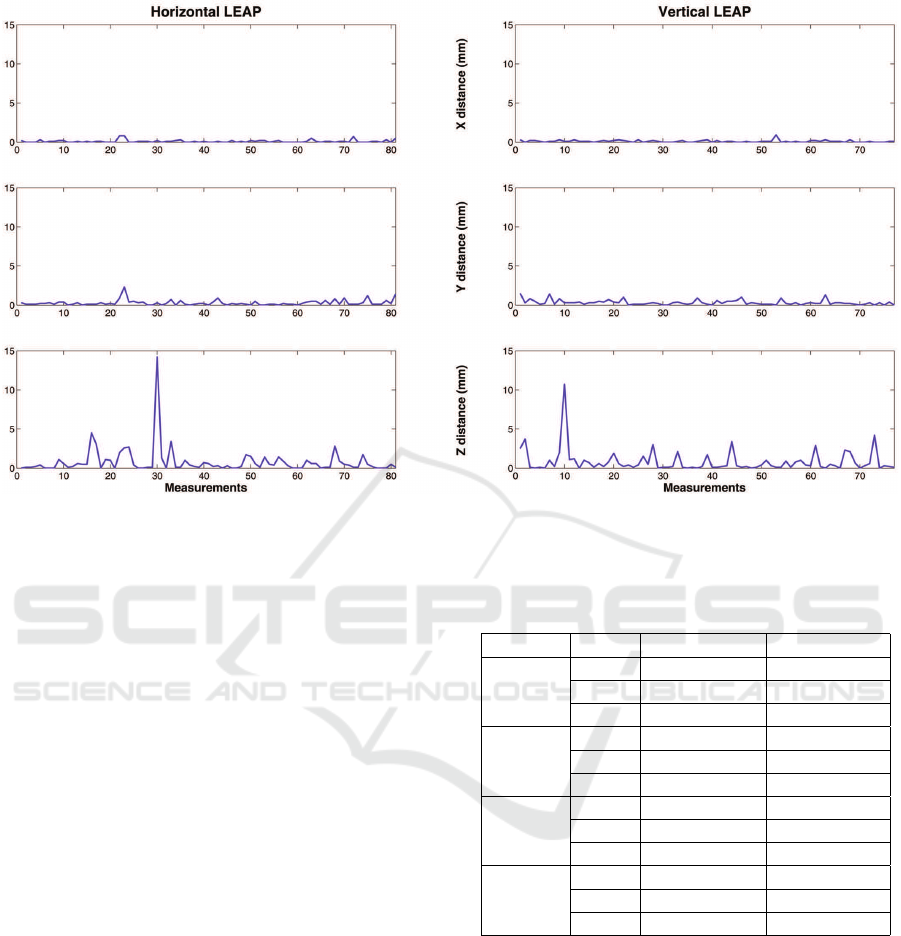
Figure 6: The distance (expressed in mm) between points measured in different conditions along the axes for the horizontal
(left panel) and vertical (right panel) sensors.
face of the disk. A set of 84 different positions of the
stick was measured from both sensors and repeated
for both conditions. A total of 3 and 7 points were
not considered during the test of the horizontal and
the vertical LEAP respectively, due to the impossibil-
ity of getting the positions (probably due to the closer
position of the points with respect to the sensor). It
has to be noted that the issue did not depend on the
infrared interferences, because the phenomenon hap-
pened in both conditions. Figure 5 shows the spatial
distribution of the points, measured with the LEAPs
without reciprocal interferences. The absolute values
of the variations in the measurements are represented
in Figure 6, for both LEAPs and separately for each
axes. Figure 7 also shows the distance between the
same points measured in different conditions.
Table 1 reports average values, standard devia-
tions and maximum values of the distance along all
the axes and in the space. Results have showed that
the displacement due to infrared interferences was
negligible (the average distance was 0.96 mm for
the horizontal LEAP and 1.03 mm for the vertical).
Moreover, by considering the axes separately, it is
possible to see that the tracking along the Z direction
was more affected by measurements “errors”. In par-
ticular, as can be seen also from Figure 6, the posi-
tions variation was most due to few points. In gen-
eral, considering the size of the fingertips and joints,
the displacement could be considered “tractable”.
Table 1: Average values, standard deviations and maximum
values of the distance along all the axes and in the space,
between points measured in different conditions.
HOR. LEAP VER. LEAP
X
distance
AVG 0.11 0.11
STD 0.17 0.13
MAX 0.80 0.90
Y
distance
AVG 0.28 0.32
STD 0.36 0.32
MAX 2.30 1.50
Z
distance
AVG 0.79 0.83
STD 1.75 1.48
MAX 14.20 10.70
3D
distance
AVG 0.96 1.03
STD 1.73 1.44
MAX 14.20 10.70
3 TRACKING MODEL
PROTOTYPE
3.1 Calibration Procedure
The proposed strategy was based on the proper rigid
transformation (roto-translation) of the vertical LEAP
information. In order to minimize the errors in the
tracking procedure, the position and the orientation
of one LEAP with respect to the other had to be eval-
A Virtual Glove System for the Hand Rehabilitation based on Two Orthogonal LEAP Motion Controllers
187
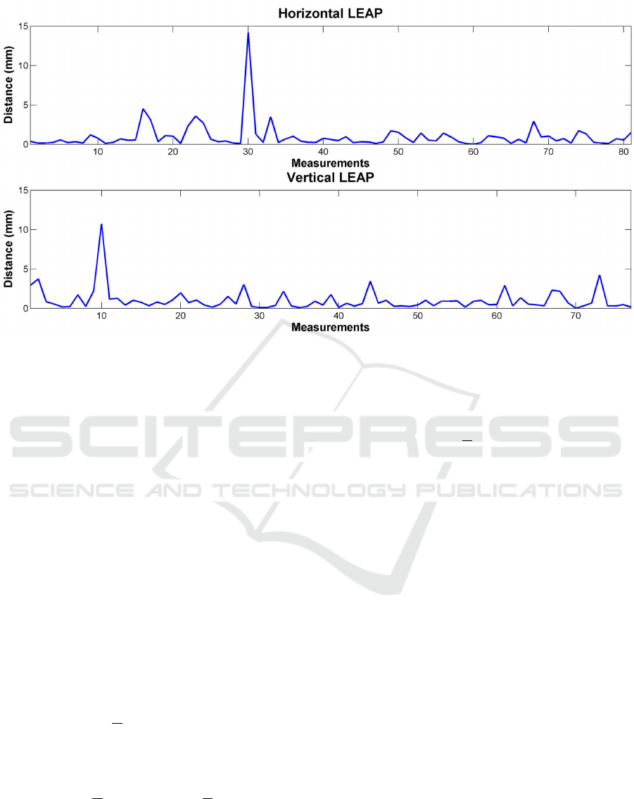
Figure 7: The distances (expressed in mm) between points measured in different conditions for the horizontal (up panel) and
the vertical (down panel) sensors.
uated as precisely as possible. The calibration pro-
cedure aimed to compute the roto-translation trans-
formation that links the vertical reference system to
the horizontal, starting from the coordinates of the
same set of points in the space observed from the
viewpoints (only one sensor was turned on during
each measure). The problem of estimating 3D body
transformations that aligns two sets of points with
known correspondences is well known in the com-
puter vision field (Sabata and Aggarwal, 1991; Eg-
gert et al., 1997). The corresponding set registra-
tion strategy used to compute the transformation (Besl
and McKay, 1992) started from two sets of points
A = {~a
i
: 1 ≤ i ≤ m} and B = {
~
b
i
: 1 ≤ i ≤ m} and
found a rotation matrix R and a translation vector
~
t
such that it was possible to move from a reference
system to the other:
~
b = R~a +
~
t, (1)
minimizing the error:
err =
1
m
m
∑
i=1
kR~a
i
+t −
~
b
i
k
2
(2)
For each set, the Center Of Mass (COM) was com-
puted:
~
C
A
=
1
m
m
∑
i=1
~a
i
and
~
C
B
=
1
m
m
∑
i=1
~
b
i
(3)
and used to center the clouds on the origin:
A
+
= {
~
a
+
i
:
~
a
+
i
= ~a
i
−
~
C
A
}
B
+
= {
~
b
+
i
:
~
b
+
i
=
~
b
i
−
~
C
B
}.
(4)
Then, the 3 x 3 cross-covariance matrix between the
sets A
+
and B
+
was computed:
H =
1
m
m
∑
i=1
~
a
+
i
~
b
+
i
T
(5)
and the Singular Value Decomposition (SVD) was ap-
plied, in order to decompose H in the vector of trans-
formations [U,S,V ] = SV D(H), such that
H = USV
T
(6)
where U and V were orthogonal matrices and S was a
non-negative diagonal matrix. Since the desired trans-
formation R was a rigid rotation, it could be computed
as:
R = UV
T
. (7)
The sign of the determinant ∆(V ) had not to be nega-
tive: in this case the third column of V was multiplied
for -1 and R was computed again. The translation was
derived as follows:
~
t = −R
~
C
A
+
~
C
A
. (8)
Lastly, the roto-translation was summarized with a
unique matrix (represented in homogeneous coordi-
nates):
W =
R
1,1
R
1,2
R
1,3
t
1
R
2,1
R
2,2
R
2,3
t
2
R
3,1
R
3,2
R
3,3
t
3
0 0 0 1
. (9)
The calibration phase was implemented in MATLAB
to run off-line. Given the set of points P, and fol-
lowing a cross validation strategy, the described point
ICPRAM 2017 - 6th International Conference on Pattern Recognition Applications and Methods
188
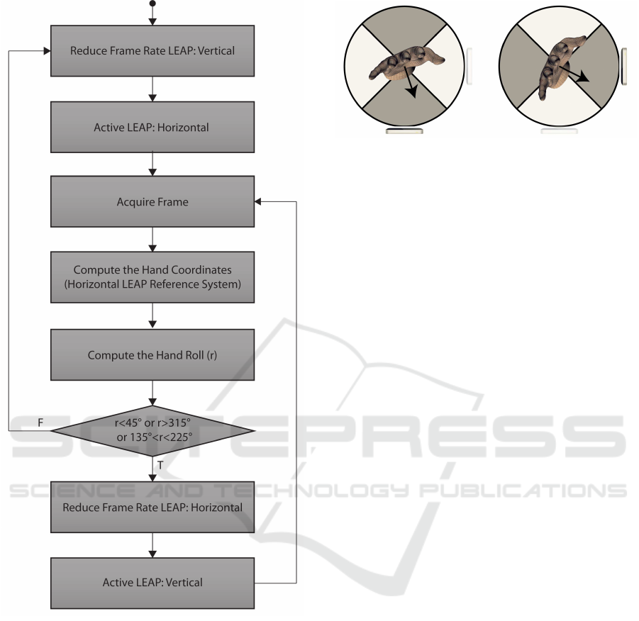
Figure 8: The flow diagram of the tracking prototype: the
hand was tracked by both sensors, the roll r with respect to
the horizontal reference system was computed using the in-
formation from the active LEAP and used to determine the
active sensor. The calibration was done in order to consider
the horizontal LEAP reference system as the world refer-
ence system.
registration process could be iterated k time, random
selecting, at each step, the training subset T
k
⊂ P (with
|T
k
| = s) used for the registration and computing the
average distance (between a point seen from the hor-
izontal sensor and the roto-translation of the same
point seen from the vertical sensor), over the remain-
ing set P \ T
k
. At the end, the training set character-
ized by the lowest distance was selected and the corre-
sponding roto-translation matrix stored in order to be
Figure 9: The switching approach: depending on the orien-
tation of the hand, one of the sensor was active and used to
track the hand, while the other was paused, in order to save
computational resources.
used by the server in run-time. This choice was made
to avoid that points affected by not negligible mea-
surement errors could affect negatively the calibration
process. P, k and s were the input of the calibration
function.
3.2 Tracking Module
The proposed approach could be easily employed in
a hand tracking system. The process to obtain the po-
sitions, illustrated in Figure 8, was based on a con-
trol switching approach: both LEAPs acquired their
frames stream, but only one, depending on the rota-
tion of the hand with respect to the horizontal LEAP
references system, is used to represent the hand (Fig-
ure 9). Both LEAPs were simultaneously turned on
and remained in this state for the whole session be-
cause the time necessary to switch on and off a sen-
sor would be too high for real-time purposes. At
each time, only one LEAP was selected as “active”
and the corresponding frame was acquired and used
to track the hand. The vector v, orthogonal to the
palm and usually used by the sensor to estimate the
hand orientation, was used to compute the roll r of
the hand, that is the angle between the X axis and the
projection of the vector on the X-Y plane, with re-
spect to the horizontal LEAP reference system. As
shown in Figure 9, if r was in the range from 225
◦
to 315
◦
(the palm was facing downwards) or in the
range from 45
◦
to 135
◦
(the palm was directed up-
wards) the horizontal LEAP was selected as active,
while the vertical was “paused” (it was still turned
on, but its frame rate was reduced to the minimum
in order to save computational resources). Out of
these ranges, the vertical and the horizontal LEAPs
had to act in the opposite way: the vertical was
active and the horizontal was paused. The proto-
type has been developed following the architecture
scheme shown in Figure 4: the server component
received data from routers and manipulated the in-
formation from the vertical LEAP (that is the data
A Virtual Glove System for the Hand Rehabilitation based on Two Orthogonal LEAP Motion Controllers
189
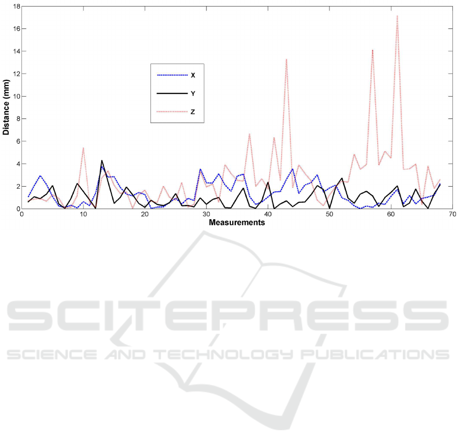
Figure 10: The distance computed along the axes during the calibration procedure.
from the Slave router) performing a roto-translation
to obtain the coordinates with respect to the horizon-
tal LEAP reference system. The server was respon-
sible to check which LEAP was active, to send only
the information received from it to the client and, if
needed, to change the active status of the sensors. The
client was obtained by using a modified version of an
example application included in the LeapJS frame-
work (http://github.com/leapmotion/leapjs, 2016),
“Threejs-bones.html”.
3.3 Preliminary Results
In order to observe the online behavior of the system,
the calibration procedure was performed by using a
cloud of 68 points (P = 68). The size s of T
k
was
set to 5. The registration was iterated k = 3 ∗ 10
4
times. The points was acquired by means of the same
tool used for the infrared interference evaluation (Fig-
ure 3). The average distance of the selected train-
ing set was err = 3.62mm, with standard deviation
σ = 2.89mm and a maximum value M = 17.36mm.
As it is possible to observe from Figure 10, like in
the infrared interference analysis, there was a small
group of points with large distance values and the “er-
ror” was concentrated on the Z axis. This suggested
that distance was mostly due to the intrinsic impre-
cision of the sensors along the Z axis than to a cali-
bration lack in accuracy. Anyway, also in this case,
the average distance was not too large with respect to
the size of the fingertips and joints and the accuracy
was acceptable. Figure 11 shows a set of hand po-
sitions and the corresponding model reconstructions,
obtained with the proposed approach. The accuracy
and the fluidity of the tracking process were adequate
(about 25 frames per second) and the change of per-
spective did not produce any jumps or other visually
observable effects. Moreover the hand was correctly
tracked also in those positions that would be critical
in the single sensor scenario.
4 CONCLUSIONS
A multi-sensor approach for hand tracking, based on
the use of two orthogonal LEAP sensors, was pre-
sented. The hardware and software design choices
and the resulting development was illustrated and dis-
cussed. A calibration procedure, aiming to align the
reference system of the LEAP has been proposed and
evaluated in term of accuracy. The detected discrep-
ancy was not enough to compromise the operation of
the system. Experimental data, to observe the be-
havior of the system in presence of infrared interfer-
ences, showed an adequate tolerance to the disturb.
An interesting result regarded the displacement dis-
tribution along the axes: the Z direction seemed to
be more affected by disturb with respect to the others
(this occurred also during calibration). This suggested
that, both in the infrared interferences and in the refer-
ence system roto-translation experiments, most of the
discrepancy was not introduced by the proposed ap-
proaches, but was due to an intrinsic lack of accuracy
of the LEAP along the Z direction. In order to ex-
plore the phenomenon, future developments will con-
ICPRAM 2017 - 6th International Conference on Pattern Recognition Applications and Methods
190
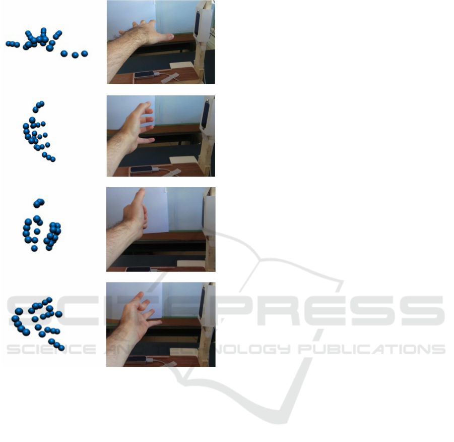
Figure 11: Examples of hand positions with the correspond-
ing model obtained by means of the proposed prototype.
Also critical positions for the single sensor scenario have
been correctly tracked.
cern the use of a refined and graduated setup tool or an
external position sensor ((Placidi et al., 2007)) to be
used for the definition of a “real” reference system, in
order to measure the accuracy of the LEAP and take
it into consideration during the assessment of the pro-
posed system effectiveness. Regarding the proposed
hand tracking prototype, it could be improved by sub-
stituting the turnover strategy with the fusion of the
models from the two LEAPs, instead of using just one
of them at once. In this case also residual occlusions
could be better overcome. Moreover, synchronizza-
tion issues should be studied and managed. Finally,
the proposed system will be tested for rehabilitation
purposes.
REFERENCES
Arya, K. N., Pandian, S., Verma, R., and Garg, R. K. (2011).
Movement therapy induced neural reorganization and
motor recovery in stroke: a review. Journal of body-
work and movement therapies, 15(4):528–537.
Avola, D., Spezialetti, M., and Placidi, G. (2013). Design
of an efficient framework for fast prototyping of cus-
tomized human–computer interfaces and virtual envi-
ronments for rehabilitation. Computer Methods and
Programs in Biomedicine, 110(3):490–502.
Bachmann, D., Weichert, F., and Rinkenauer, G. (2015).
Evaluation of the leap motion controller as a new
contact-free pointing device. Sensors, 15(1):214.
Besl, P. J. and McKay, N. D. (1992). A method for registra-
tion of 3-d shapes. IEEE Trans. Pattern Anal. Mach.
Intell., 14(2):239–256.
Burgar, C. G., Lum, P. S., Shor, P. C., and Van Der Loos,
H. F. M. (2000). Development of robots for rehabil-
itation therapy: The palo alto va/stanford experience.
Journal of Rehabilitation Research and Development,
37(6):663–673.
Charles, D., Pedlow, K., McDonough, S., Shek, K., and
Charles, T. (2014). Close range depth sensing cameras
for virtual reality based hand rehabilitation. Journal of
Assistive Technologies, 8(3):138–149.
Chaudhary, A., Raheja, J. L., Das, K., and Raheja, S.
(2013). Intelligent approaches to interact with ma-
chines using hand gesture recognition in natural way:
a survey. arXiv preprint arXiv:1303.2292.
Eggert, D. W., Lorusso, A., and Fisher, R. B. (1997). Esti-
mating 3-d rigid body transformations: a comparison
of four major algorithms. Machine Vision and Appli-
cations, 9(5):272–290.
Franchi, D., Maurizi, A., and Placidi, G. (2009). A nu-
merical hand model for a virtual glove rehabilitation
system. In Proc. of the IEEE Med. Meas. & Appl.,
MeMeA 2009, pages 41–44.
Franchi, D., Maurizi, A., and Placidi, G. (2010). Charac-
terization of a simmechanics model for a virtual glove
rehabilitation system. In Computational Modeling of
Objects Represented in Images, volume 6026, pages
141–150.
Hallett, M. (2001). Plasticity of the human motor cortex
and recovery from stroke. Brain Research Reviews,
36(2):169–174.
http://developer.leapmotion.com (Accessed: 2016). Leap
motion developers.
http://github.com/leapmotion/leapjs (Accessed: 2016).
Javascript client for the leap motion controller.
http://nodejs.org (Accessed: 2016). Node.js.
http://www.leapmotion.com (Accessed: 2016). Leap mo-
tion inc.
Kahn, L. E., Lum, P. S., Rymer, W. Z., and Reinkensmeyer,
D. J. (2006). Robot-assisted movement training for
the stroke-impaired arm: Does it matter what the robot
does? Journal of rehabilitation research and develop-
ment, 43(5):619.
Kopp, B., Kunkel, A., M
¨
unickel, W., Villringer, K., Taub,
E., and Flor, H. (1999). Plasticity in the motor system
A Virtual Glove System for the Hand Rehabilitation based on Two Orthogonal LEAP Motion Controllers
191

related to therapy-induced improvement of movement
after stroke. Neuroreport, 10(4):807–810.
Liepert, J., Bauder, H., Miltner, W. H. R., Taub, E., and
Weiller, C. (2000). Treatment-induced cortical reorga-
nization after stroke in humans. Stroke, 31(6):1210–
1216.
Llor
´
ens, R., No
´
e, E., Colomer, C., and Alca
˜
niz, M. (2015).
Effectiveness, usability, and cost-benefit of a vir-
tual reality–based telerehabilitation program for bal-
ance recovery after stroke: A randomized controlled
trial. Archives of physical medicine and rehabilita-
tion, 96(3):418–425.
Lum, P. S., Godfrey, S. B., Brokaw, E. B., Holley, R. J., and
Nichols, D. (2012). Robotic approaches for rehabili-
tation of hand function after stroke. American Journal
of Physical Medicine & Rehabilitation, 91(11):S242–
S254.
Maciejasz, P., Eschweiler, J., Gerlach-Hahn, K., Jansen-
Troy, A., and Leonhardt, S. (2014). A survey on
robotic devices for upper limb rehabilitation. J. Neu-
roeng. Rehabil, 11(1):10–1186.
Petracca, A., Carrieri, M., Avola, D., Basso Moro, S.,
Brigadoi, S., Lancia, S., Spezialetti, M., Ferrari, M.,
Quaresima, V., and Placidi, G. (2015). A virtual
ball task driven by forearm movements for neuro-
rehabilitation. In Virtual Rehabilitation Proceed-
ings (ICVR), 2015 International Conference on, pages
162–163.
Placidi, G. (2007). A smart virtual glove for the hand tel-
erehabilitation. Computers in Biology and Medicine,
37(8):1100–1107.
Placidi, G., Avola, D., Ferrari, M., Iacoviello, D., Petracca,
A., Quaresima, V., and Spezialetti, M. (2014). A low-
cost real time virtual system for postural stability as-
sessment at home. Computer methods and programs
in biomedicine, 117(2):322–333.
Placidi, G., Avola, D., Iacoviello, D., and Cinque, L.
(2013). Overall design and implementation of the
virtual glove. Computers in biology and medicine,
43(11):1927–1940.
Placidi, G., Franchi, D., Marsili, L., and Gallo, P. (2007).
Development of an auxiliary system for the execu-
tion of vascular catheter interventions with a reduced
radiological risk; system description and first experi-
mental results. Computer Methods and Programs in
Biomedicine, 88(2):144–151.
Placidi, G., Petracca, A., Pagnani, N., Spezialetti, M., and
Iacoviello, D. (2015). A virtual system for postural
stability assessment based on a tof camera and a mir-
ror. In Proceedings of the 3rd 2015 Workshop on ICTs
for Improving Patients Rehabilitation Research Tech-
niques, pages 77–80.
Polsinelli, M. (2015). Implementation of a virtual glove
for rehabilitation through the use of leap motion con-
trollers. Master’s thesis, University of L’Aquila.
Rus
`
ak, Z., Antonya, C., and Horv
`
ath, I. (2011). Methodol-
ogy for controlling contact forces in interactive grasp-
ing simulation. International Journal of Virtual Real-
ity, 10(2):1.
Sabata, B. and Aggarwal, J. K. (1991). Estimation of mo-
tion from a pair of range images: A review. CVGIP:
Image Understanding, 54(3):309 – 324.
Weichert, F., Bachmann, D., Rudak, B., and Fisseler, D.
(2013). Analysis of the accuracy and robustness of the
leap motion controller. Sensors, 13(5):6380–6393.
Zimmerli, L., Jacky, M., L
¨
unenburger, L., Riener, R.,
and Bolliger, M. (2013). Increasing patient engage-
ment during virtual reality-based motor rehabilita-
tion. Archives of physical medicine and rehabilitation,
94(9):1737–1746.
ICPRAM 2017 - 6th International Conference on Pattern Recognition Applications and Methods
192
