
Network and Topology Models to Support IDS Event Processing
J
¨
org Kippe and Steffen Pfrang
Fraunhofer IOSB, Fraunhoferstr. 1, 76131 Karlsruhe, Germany
{joerg.kippe, steffen.pfrang}@iosb.fraunhofer.de
Keywords:
Intrusion Detection, Network Modeling, Network Awareness, YANG.
Abstract:
This paper describes our work on network models to provide awareness to the process of correlating network
security alerts as well as to support the asset assessment process within the security analysis of IT infrastruc-
tures. Various means of discovery methods mostly known from network management are used to discover
nodes, their properties as well as the links connecting the nodes and building a network. Our implementation
is based on existing open source components which have been integrated together and are using an information
model according to proposed open standards.
1 INTRODUCTION
This paper presents research results concerning the
generation of network models representing nodes and
topological structure of IT infrastructures based on
automatic discovery. The primary aim is to use such
a model to support the process of event correlation
for intrusion detection, but the collected data is also
useful for tasks like asset assessment. The work de-
scribed is part of our research program on distributed
intrusion detection frameworks, which covers various
aspects of data collection and analysis like
• network traffic monitoring for signature-based de-
tection of suspicious packets
• network traffic monitoring for flow-based analysis
of communication patterns
• host based log monitoring and file system in-
tegrity checking
• integration of network management applications
for status monitoring, node, service and link dis-
covery, passive OS fingerprinting and vulnerabil-
ity discovery
The essential design objective is to use separate
available open source products and to combine and
to integrate them using open standard protocols and
standard data models for the information exchange
as far as possible. The objective of the work is to
improve the IT security of industrial automation net-
works (process control, manufacturing) in general and
those IT systems controlling critical infrastructures
and utility networks (electricity, gas, water) in par-
ticular. The paper begins with a survey of the state of
the art. Paragraph 3 then presents our implementation
architecture and paragraph 4 some ideas about the po-
tential benefits and usages of network awareness.
2 STATE OF THE ART
This paragraph gives a short overview on the previous
work about network awareness of Intrusion Detection
System in general and on network and network topol-
ogy modeling in particular.
2.1 The Idea of Network Awareness
Network awareness may be understood as the ability
to answer questions about the network, its structure
and its behavior. It is expected that this kind of in-
formation will improve the accuracy of the intrusion
detection process.
One of the earliest papers on the topic of IDS net-
work awareness (to the best of our knowledge) dates
back to 1998 (Ptacek and Newsham, 1998). The
authors discuss different weaknesses and vulnerabil-
ities of network-based intrusion detections systems.
Their general statement is that those weaknesses are
due to ambiguities concerning the processing of data
packets by target systems that an IDS cannot resolve.
In his talks 2001 (Roesch, 2001) and 2004 (Roesch,
2004) M. Roesch pointed out the importance of net-
work awareness and proposed the concept of Target-
based IDS (TIDS) and Real Time Network Awareness
(RNA). He mentioned that actual network security de-
vices are working in a contextual vacuum as they have
372
Kippe, J. and Pfrang, S.
Network and Topology Models to Suppor t IDS Event Processing.
DOI: 10.5220/0006189403720379
In Proceedings of the 3rd International Conference on Information Systems Security and Privacy (ICISSP 2017), pages 372-379
ISBN: 978-989-758-209-7
Copyright
c
2017 by SCITEPRESS – Science and Technology Publications, Lda. All rights reserved

no knowledge about network topology, network as-
sets and asset criticality. He proposed to improve the
intrusion detection process by using Passive Network
Discovery Systems (PNDS). Passive discovery uses
packet sniffing to find nodes in the network. It oper-
ates invisible and will never release a packet into the
network. A comprehensive survey on passive detec-
tion methods is provided by (DeMontigny and Mas-
sicotte, 2004). Examples of passive discovery tools
are PRADS
1
and its two older predecessors p0f
2
and
PADS
3
. These applications check a set of parameters
which are set differently by different operating sys-
tems (e.g. time to live, window size, don’t fragment
flag, type of service). Analyzing these parameters al-
low to guess the remote operating system. Addition-
ally observed packets provide information concern-
ing active clients and servers and the related services.
Sourcefire and other IDS vendors like Cisco
4
have
provided solutions to scan the protected network and
to assess alerts for many years now. Those commer-
cial products are closed source software, therefore lit-
tle information is available on the technical details of
the implementation. A solution available in the open
source domain is the Host Attributes Table which can
be used with the open source network IDS system
Snort
5
.
2.2 Network Modelling
The systematic description of network structures has
a long tradition. A well known approach is the 7-
layer-model from OSI (ITU-R, 1994). A more for-
mal way of description based on a logic oriented ap-
proach which also covers security related informa-
tion and the usage within intrusion detection systems
was presented by (Vigna, 2003) and (Morin, 2002).
A rich management model which has been provided
by the Desktop Management Task Force
6
(DMTF) is
the Common Information Model (CIM). The Splunk
7
product for collecting and analyzing high volumes of
log data gains network awareness by an add-on mod-
ule making use of the CIM model.
Another approach is related to the NETCONF
Data Modeling Language Working Group (NET-
MOD
8
). They have developed a high-level data mod-
eling language for the NETCONF protocol called
1
http://prads.projects.linpro.no/
2
http://lcamtuf.coredump.cx/p0f3/
3
http://passive.sourceforge.net/
4
http://www.cisco.com/c/en/us/td/docs/security/firesight
5
http://www.snort.org
6
http://dmtf.org/standards/cim
7
https://www.splunk.com/
8
https://datatracker.ietf.org/wg/netmod/charter/
YANG (RFC 6020) (Bjorklund, 2010). This is ac-
companied by RFC 6991 (Schoenwaelder, 2013),
which introduces a collection of common data types
to be used with the YANG data modeling language.
YANG is a data modeling language used to model
configuration and state data manipulated by the NET-
CONF protocol, NETCONF remote procedure calls
and NETCONF notifications. YANG has also been
used to do network modeling. There are three IETF
drafts (work in progress) available dealing with the
basics of network modeling and network topology
modeling. Clemm et al. (Clemm et al., 2016) describe
an abstract and generic YANG data model for net-
work/service topologies and inventories. This serves
as a base model which can be augmented with specific
details in other more specific models.
3 ARCHITECTURE AND
IMPLEMENTATION
Our implementation architecture is based on a set of
functional modules realizing various components of a
distributed intrusion detection system. An overview
of the network model related part of the distributed
architecture is given in Figure 1. This comprises the
following modules:
• The Inventory Server is performing node and
service discovery and is providing an inventory
model. This is done passively by using the open
source product PRADS. The network traffic is
captured and analyzed using a set of signatures.
The PRADS output log file is read and formatted
according to our YANG-based inventory model.
• The Topology Server is providing a topology
model. This server uses the discovery func-
tionality of the open source network manage-
ment system OpenNMS
9
. Its discovery mod-
ule utilizes various SNMP MIBs (basically the
BRIDGE-MIB (Norseth and Bell, 2005)) to col-
lect topology-related data which is stored in a
SQL database. The Topology Server processes
data from this database and generates an XML-
encoded topology model according to our YANG-
based model descriptions. This automatically
retrieved information is supplemented by asset-
related information (the asset database is realized
by some other tables of the OpenNMS database),
which is maintained manually. This is a kind of
Configuration Management Database (CMDB),
which we are using here to provide information
9
http://www.opennms.org
Network and Topology Models to Support IDS Event Processing
373
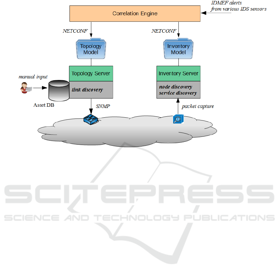
Figure 1: Overview of the implementation architecture.
about the category of the network device and its
role within the network.
The Correlation Engine (shown in the upper range
of Figure 1) processes various streams of IDMEF
(Debar et al., 2007) alerts originating from vari-
ous IDS sensor components. We are working with
network-based (signature-based and flow-based) as
well as host-based sensor components. The Correla-
tion Engine accesses network related information by
utilizing a NETCONF (Enns et al., 2011) based north-
bound interface through which the Inventory and the
Topology Server are providing the model information.
3.1 The Network Model
Based on the literature mentioned above in paragraph
2 about the provision of network awareness to IDS we
identified a set of properties which a network model
must provide. We believe the most relevant are:
• The network model should be a formal description
based on standards.
• The network model should be easily extendable to
add new information.
• The network model should be able to represent
static knowledge about topology structure as well
as more dynamic knowledge about the actual sta-
tus of network components.
Our implementation of the network model is
based on the abstract YANG data model developed
by the IETF (as pointed out in subsection 2.1.1). This
base model (module name ietf-network) allows to de-
fine network hierarchies and an inventory of nodes
contained within a network. A second model aug-
ments the basic model to describe topology informa-
tion (module name ietf-network-topology).
3.1.1 Objects and Structure of the Model
Four different types of model objects are used to build
our topology model: network, node, termination point
and link. A network represents a certain aspect of an
IT infrastructure and has a certain type (layer-1, layer-
2, etc.). Networks may be organized in a hierarchy
using the relation supporting-network (a supporting-
network is an underlay network) and this way build-
ing a stack of networks. A network may contain two
other types of objects: nodes and links. The node
object represents a certain aspect or abstraction of a
network element (an end system or an intermediate
system). As networks, nodes may have supporting-
nodes mapping to other nodes in an underlay network.
Nodes are connected by links. Their anchor points are
objects of type termination point, which are contained
within the nodes and represent an interface (physi-
cal or logical port). The containment structure of the
model objects is shown in Figure 2. The schema of
a point-to-point connection between two node objects
is illustrated by Figure 3.
A special object type we are making use of is the
pseudonode. A pseudonode represents a multipoint
network representing e.g. an IP subnet or a VLAN
(this is illustrated by Figure 4).
ICISSP 2017 - 3rd International Conference on Information Systems Security and Privacy
374
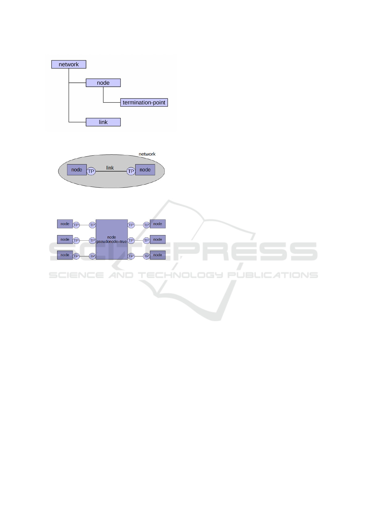
Figure 2: The containment hierarchy of the model objects.
Figure 3: Schema of the mode structure.
Figure 4: Schema of modeling a multipoint network using
a pseudonode object.
In the following the YANG tree diagrams show
the hierarchical structure of the modules ietf-network
and ietf-network-topology. Brackets enclose list keys,
”rw” means configuration data (read-write), ”ro”
means operations state data (read-only), ”*” denotes
a list and leaf-list, ”!” means a presence container
and ”?” designates optional nodes. Parentheses en-
close choice and case nodes, and case nodes are also
marked with a colon (”:”). Ellipses (”...”) stand for
contents of sub-trees that are not shown (explanation
according to (Bierman, 2016)). To avoid confusion it
should be noted that there two ways to denote the dif-
ference between configuration data (read-write) and
state data (read-only). The models presented here are
intended to be used in both usage scenarios, there-
fore the distinction is made using the attribute ”server-
provided”, indicating whether the data is produced by
some server-based discovery process or not.
module: ietf-network
+--rw networks
+--rw network* [network-id]
+--rw network-types
+--rw network-id network-id
+--ro server-provided? boolean
+--rw supporting-network* [network-ref]
| +--rw network-ref
-> /networks/network/network-id
+--rw node* [node-id]
+--rw node-id node-id
+--rw supporting-node*
[network-ref node-ref]
+--rw network-ref
-> ../../../supporting-network
/network-ref
+--rw node-ref
-> /networks/network
/node/node-id
module: ietf-network-topology
augment /nd:networks/nd:network:
+--rw link* [link-id]
+--rw source
| +--rw source-node?
-> ../../../nd:node/node-id
| +--rw source-tp?
-> ../../../nd:node[nd:node-id=current()
/../source-node]
/termination-point/tp-id
+--rw destination
| +--rw dest-node?
-> ../../../nd:node/node-id
| +--rw dest-tp?
-> ../../../nd:node[nd:node-id=current()
/../dest-node]/termination-point/tp-id
+--rw link-id link-id
+--rw supporting-link*
[network-ref link-ref]
+--rw network-ref
-> ../../../nd:supporting-network/network-ref
+--rw link-ref
-> /nd:networks
/network[nd:network-id=current()/..
/network-ref]/link/link-id
augment /nd:networks/nd:network/nd:node:
+--rw termination-point* [tp-id]
+--rw tp-id tp-id
+--rw supporting-termination-point*
[network-ref node-ref tp-ref]
+--rw network-ref
-> ../../../nd:supporting-node/network-ref
+--rw node-ref
-> ../../../nd:supporting-node/node-ref
+--rw tp-ref
->/nd:networks/network[nd:network-id=current()
/../network-ref]/node[nd:node-id=current()
/../node-ref]/termination-point/tp-id
For our implementation we have defined the four
YANG modules described below, which augment
the basic model to describe two specific network
Network and Topology Models to Support IDS Event Processing
375

models: the Inventory and the Topology Model.
These reflect the different aspects of our model-
ing from layer 1 up to layer 3. Their mod-
ule names are silab-network-inventory, silab-layer-
1-topology, silab-layer-2-topology and silab-layer-3-
topology. The respective model hierarchy is shown in
Figure 5.
Figure 5: Model Hierarchies.
3.1.2 The Inventory Model
The Inventory Model (module name: silab-network-
inventory) describes information retrieved by passive
asset detection and provides the nodes found in the
network together with additional information con-
cerning IP address, MAC address, operating system
and discovered service and client ports. The respec-
tive YANG tree diagram is shown below:
module: silab-network-inventory
augment /nd:networks/nd:network/nd:node:
+--rw phys-addr? yang:phys-address
+--rw dns-name? inet:domain-name
+--rw os-version? string
+--rw ip-addr? inet:ip-address
+--rw services
| +--rw service* [port]
| +--rw port inet:port-number
+--rw clients
+--rw client* [port]
+--rw port inet:port-number
3.1.3 The Topology Model
The Topology Model describes the topology and the
hierarchical structure of the network on three layers
(physical, link layer and network layer) using three
respective network types. These are derived from the
IETF provided base network model (module name:
ietf-network) and topology network model (module
name: ietf-network-topology).
The Physical Layer Model (or Layer-1-Model
according to the OSI model; module name: silab-
layer-1-topology) describes the physical layer of an
IT infrastructure. The nodes within this network
model represent the existing physical boxes and the
links represent the cabling in between. The model de-
scription is built by augmenting the base and topology
network model.
module: silab-layer-1-topology
augment /nd:networks/nd:network/nd:network-types:
+--rw l1-network!
augment /nd:networks/nd:network:
+--rw l1-network-attributes
+--rw name? string
augment /nd:networks/nd:network/nd:node:
+--rw l1-node-attributes
+--rw name? string
+--rw description? string
+--rw timestamp? uint32
+--rw pseudonode? boolean
+--rw category? enumeration
augment /nd:networks/nd:network/lnk:link:
+--rw l1-link-attributes
+--rw name? string
augment /nd:networks/nd:network/nd:node
/lnk:termination-point:
+--rw l1-termination-point-attributes
+--rw description? string
+--rw type? string
The Link Layer Model (or Layer-2-Model ac-
cording to the OSI model; module name: silab-layer-
2-topology) describes a physical or logical (virtual)
layer 2 network. The nodes within the network model
represent the link layer of the respective network ele-
ments which are connected to a pseudonode instance
which represents a VLAN segment (according to the
schema illustrated by Figure 4). The termination-
point objects in this model contain the respective layer
2 attributes. As mentioned above, the model descrip-
tion is built by augmenting the base and topology net-
work model.
module: silab-layer-2-topology
augment /nd:networks/nd:network/nd:network-types:
+--rw l2-network!
augment /nd:networks/nd:network:
+--rw l2-network-attributes
+--rw name? string
augment /nd:networks/nd:network/nd:node:
+--rw l2-node-attributes
+--rw name? string
+--rw description? string
+--rw pseudonode? boolean
+--rw timestamp? int32
augment /nd:networks/nd:network/lnk:link:
+--rw l2-link-attributes
+--rw name? string
augment /nd:networks/nd:network/nd:node
/lnk:termination-point:
+--rw l2-termination-point-attributes
+--rw description? string
+--rw type? identityref
+--rw if-index? int32 {if-mib}?
+--rw mac-address? yang:mac-address
ICISSP 2017 - 3rd International Conference on Information Systems Security and Privacy
376

The Network Layer Model (or Layer-3-Model
according to the OSI model; module name: silab-
layer-3-topology) describes a layer 3 network. The
nodes within the network model represent the net-
work layer of the respective network elements which
are connected to a pseudonode instance which rep-
resents an IP subnet (according to the schema illus-
trated by Figure 4). The termination-point objects in
this model contain the respective layer 3 attributes.
As mentioned above, the model description is built by
augmenting the base and topology network model.
module: silab-layer-3-topology
augment /nd:networks/nd:network/nd:network-types:
+--rw l3-network!
augment /nd:networks/nd:network:
+--rw l3-network-attributes
+--rw name? string
augment /nd:networks/nd:network/nd:node:
+--rw l3-node-attributes
+--rw name? string
+--rw description? string
+--rw pseudonode? boolean
augment /nd:networks/nd:network/lnk:link:
+--rw l3-link-attributes
+--rw name? string
augment /nd:networks/nd:network/nd:node
/lnk:termination-point:
+--rw l3-termination-point-attributes
+--rw description? string
+--rw ipv4!
+--rw enabled? boolean
+--rw forwarding? boolean
+--rw address* [ip]
| +--rw ip
inet:ipv4-address-no-zone
| +--rw (subnet)
| +--:(prefix-length)
| | +--rw prefix-length?
uint8
| +--:(netmask)
| +--rw netmask?
yang:dotted-quad
{ipv4-non-contiguous-netmasks}?
+--rw neighbor* [ip]
+--rw ip
inet:ipv4-address-no-zone
+--rw link-layer-address
yang:phys-address
Figure 6 shows an example of a topology hierar-
chy. The bottom layer is build by the physical model
representing the physical devices and the cabling con-
necting the physical devices. On top we have modeled
two different VLANs represented each by a layer 2
network. On this layer the nodes are representing the
layer 2 implementation of our devices connected to a
pseudonode which stands for a VLAN. The top level
is built by two layer 3 networks representing two dif-
ferent IP subnets.
3.2 Additional Data Sources
In addition to the results of the OpenNMS discovery
process, other data from the OpenNMS database is
used. Those tables are building die OpenNMS Asset
DB (or in ITIL
10
terms the Configuration Manage-
ment Database (CMDB)). We are using information
concerning the type of devices, which is added man-
ually to this database.
The OpenNMS discovery approach relies on the
availability and the proper implementation of SNMP
agents on mostly all network devices. This is not al-
ways found in every network installation. The most
important information which is missing in this case
is the mapping between IP address and MAC ad-
dress. As a replacement solution we have integrated
an arpwatch
11
probe which provides through the ARP
database the missing information. Further in our test
environment we have virtual Open vSwitches
12
in use
which don’t support SNMP management. In this case
as a replacement solution we provide the address for-
warding table information via script interface to the
topology server.
3.3 Testing the Implementation
Our current implementation of the work as described
is a proof-of-concept prototype. The components are
fully implemented and the usage of the provided net-
work information in the correlation engine is tested in
our laboratory environment. This is a test and devel-
opment environment for IT security in industrial au-
tomation networks (Pfrang et al., 2016). It consists
of a physical part and a virtual part, both are con-
nected via VLAN trunks. Within the physical part we
have industrial components like PLCs, sensors, ac-
tors, industrial network elements (switches and fire-
walls). Within the virtual part (i.e. based on a virtual-
ization platform), we have different virtual networks
built up using virtual switches and virtual firewalls
and a set of virtual machines performing process au-
tomation related functions (SCADA server, OPC-UA
server, PLC programming stations) as well as attack
and monitoring tools for security related experiments.
Within this environment, the inventory and the
topology server are installed on virtual machines. The
scope of our tests is defined by the networks dis-
covered by our network management systems (Open-
NMS). We have used 4 IP subnets, 3 of them spread
across the virtual and the physical part, 1 is a virtual
10
https://www.axelos.com/best-practice-solutions/itil
11
http://ee.lbl.gov/
12
http://www.openvswitch.org/
Network and Topology Models to Support IDS Event Processing
377
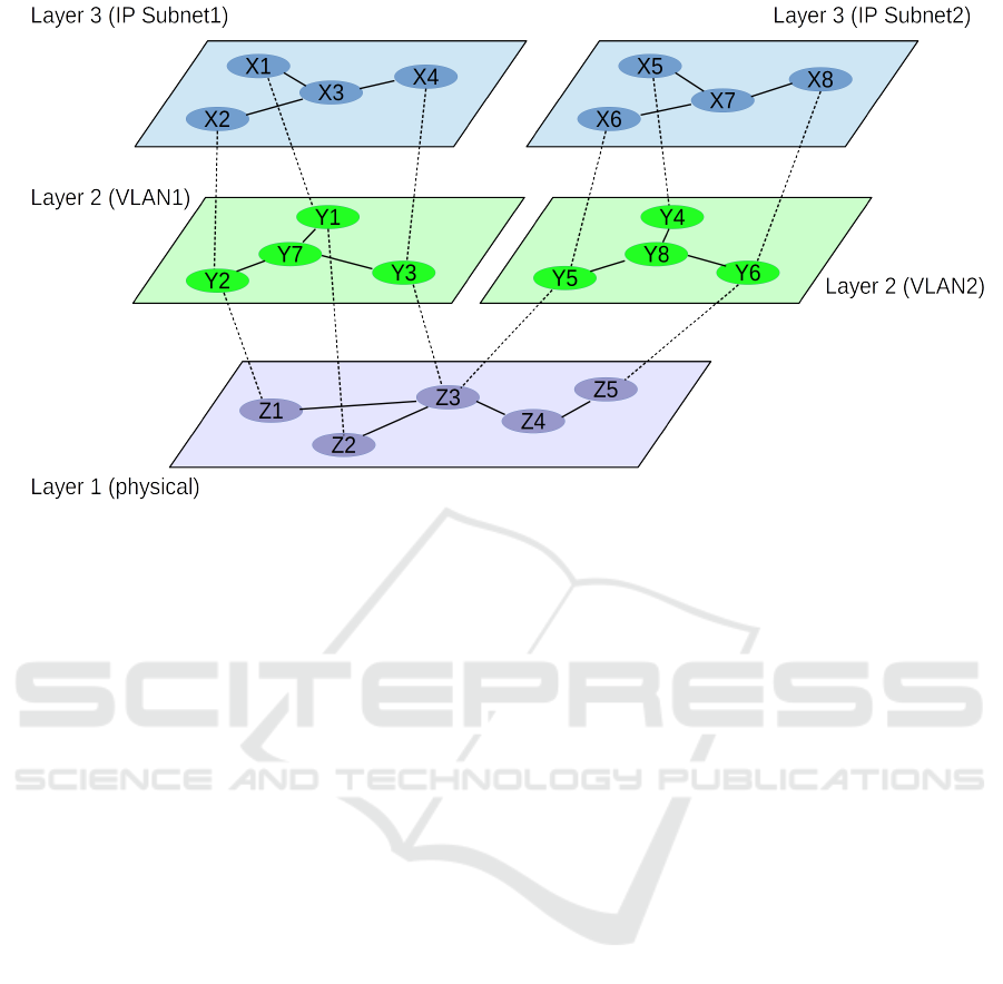
Figure 6: Example of a topology hierarchy.
subnet only. These IP subnets are supported by phys-
ical as well as virtual switches running 4 VLANs.
These networks contain 98 nodes in total. By using
additional information (as mentioned above) beside
what is available from SNMP, we achieve to discover
the complete set of nodes and the correct topological
structure.
4 USAGE SCENARIOS
The usage of the described network models within
the intrusion detection correlation process is subject
to ongoing research and has not been finished yet. In
the following we give a non comprehensive indication
of some issues which will be investigated further and
which will make use of the model generation.
• Knowledge about the vulnerabilities of a node
provide for assessment of risks of certain attack
pattern observed within the network traffic. (This
has been the original motivation to add the host-
attribute-list to Snort’s configuration.)
• Knowing the type of a node allows to draw con-
clusions about the expected type of traffic. This
e.g. means either white-listing (known client and
servers of a given service) or suppressing of false
positive alerts caused by allowed scan activities
(e.g. from the network management station).
• Conclusions drawn by the correlation process
may be expressed in terms of statements about
the network (e.g. ”TCP SYN scan in /net-
works/network[id=5]”)
• Provide for the definition of security policies, i.e.
abstraction on specific rules which will allow a
more lucid representation.
• In a multi-sensor IDS environment with different
sensors in different parts of the network the topol-
ogy model provides information concerning the
scope of each sensor.
• The topology model describes among other things
the separation of the network into segments of
subnets with network elements in between. This
separation may provide useful information with
respect to the isolation of certain protocols (e.g.
L2 protocols do not pass through routers, L2
broadcasts do not pass between VLANs) and to
the propagation of certain attacks.
• Network elements not only isolate parts of the net-
works from each other but provide for control of
the through passing traffic.
• Multi-homed hosts normally are not allowed to
pass traffic from one interface to another. There is
always the risk of improper configuration, there-
fore certain checks may be applied. Which hosts
to consider is information typically provided from
topology information.
• A central topic within IT Security and Risk Man-
agement Frameworks (e.g. (NIST, 2010) and
(IEC, 2015)) is the task of asset enumeration and
the continuous tracking of respective changes.
This usage scenario can be supported by techni-
cal assessment techniques like the automatically
generated inventory and topology models.
ICISSP 2017 - 3rd International Conference on Information Systems Security and Privacy
378

5 CONCLUSION
For the provision of network awareness to the pro-
cess of reasoning about network security issues and
to support technical assessment processes we have
designed an inventory model and a topology model.
These models have been formally described accord-
ing to modern and upcoming standards and respective
software modules for the collection of the necessary
data and the generation of the model structure have
been implemented and successfully tested. The ap-
proach relies on a proper network setup and SNMP
support at least on every network element (switches,
firewalls, routers). Missing information may be added
using a CMDB but automatically retrieved data is al-
ways preferable.
Future work will be dedicated to tests in different
network environments to improve confidence in the
implemented solution as well as the realization and
test of usage scenarios together with correlation tasks.
ACKNOWLEDGEMENTS
This work presented in this paper has been sup-
ported by the European Commission through project
FP7-SEC-607093-PREEMPTIVE funded by the 7th
Framework Program.
REFERENCES
Bierman, A. (2016). Guidelines for authors and reviewers of
yang data model documents. IETF Network Working
Group Internet-Draft, RFC6087bis, 2016.
Bjorklund, M. (2010). Yang - a data modelling language for
the network configuration protocol (netconf). IETF
RFC 6020, 2010.
Clemm, A., Medved, J., Varga, R., Tkacik, T., Bahadur,
N., Ananthakrishnan, H., and Liu, X. (2016). A data
model for network topologies. IETF Network Work-
ing Group Internet-Draft, 2016.
Debar, H., Curry, D., and Feinstein, B. (2007). The in-
trusion detection message exchange format (idmef).
IETF RFC 4765, 2007.
DeMontigny, A. and Massicotte, F. (2004). Passive net-
work discovery for real time situation awareness. In
Proc NATORTO Symp. Adapt. Def. Unclassif. Netw.,
volume 4.
Enns, R., Bjorklund, M., and Schoenwaelder, J. (2011).
Network configuration protocol (netconf). IETF RFC
6241, 2011.
IEC (2015). Iec 62443 industrial communication networks
- network and system security. International Elec-
trotechnical Commision (IEC), 2015.
ITU-R (1994). Open systems interconnection - model and
notation. ITU-R Rec. X.200, 1994.
Morin, B. (2002). M2d2: A formal data model for ids alert
correlation. In Int. Workshop Recent Adv. Intrusion
Detect. Springer Berlin Heidelberg, 2002.
NIST (2010). Guide for applying the risk management
framework to federal information systems. NIST Spe-
cial Publication 800-37, 2010.
Norseth, K. and Bell, E. (2005). Definition of managed
objects for bridges. IETF RFC 4188, 2005.
Pfrang, S., Kippe, J., Meier, D., and Haas, C. (2016). De-
sign and architecture of an industrial it security lab. In
Testbeds and Research Infrastructures for the Devel-
opment of Networks and Communities.
Ptacek, T. and Newsham, T. (1998). Insertion, evasion and
denial of service: Eluding network intrusion detec-
tion. Secure Networks, Inc.
Roesch, M. (2001). Snort. presented at the Black Hat Con-
ference 2001.
Roesch, M. (2004). Your network is talking, are you listen-
ing? presented at the CanSecWest, Vancouver 2004.
Schoenwaelder, J. (2013). Common yang data types. IETF
RFC 6991, 2013.
Vigna, G. (2003). A topological characterization of tcp/ip
security. In Int. Symp. Form. Methods Eur. Springer
Berlin Heidelberg, 2003.
Network and Topology Models to Support IDS Event Processing
379
