
Realizing Multi-variant Model Transformations
on Top of Reused ATL Specifications
Sandra Greiner, Felix Schw
¨
agerl and Bernhard Westfechtel
Applied Computer Science I, University of Bayreuth, Universit
¨
atsstr. 30, 95440 Bayreuth, Germany
Keywords:
Model-Driven Software Engineering, Software Product Line Engineering, Model Transformations, Variabil-
ity, Organized Reuse.
Abstract:
Model transformations are crucial in model-driven software engineering (MDSE). While combining MDSE
and software product line engineering (SPLE) techniques, summarized as model-driven product line engineer-
ing (MDPLE), promises increased productivity by relying on organized reuse, the benefits are impeded by
transformation specifications designed exclusively for single-variant models. Applying single-variant model
transformations to multi-variant input models results in output models lacking the variability information.
Multi-variant model transformations (MVMT), which preserve variability information, have only recently
been understood as an explicit research problem. In this paper, we propose an a posteriori approach towards
MVMT. Following the paradigm of organized reuse, we propose to employ single-variant model transfor-
mations without modifications in a first step, and to transfer variability information afterwards based on the
artifacts provided by the single-variant transformation specification. In particular, we implemented this ap-
proach for the well-known model-to-model transformation language ATL. To deduce variability information,
the execution artifacts (trace and execution model) are analyzed. Then, variability annotations are transfered
to the target model automatically. The implementation is evaluated based on a practically example of a Graph
product line. Results exhibit that our approach outperforms the conventional solution with respect to user
effort, accuracy and performance.
1 INTRODUCTION
In model-driven software engineering (MDSE), mod-
els are abstractions of systems to be transformed into
executable code eventually (V
¨
olter et al., 2006). A
metamodel, the model conforms to, defines the ab-
stract syntax of the used modeling language.
Model transformations (Mellor et al., 2004) con-
vert one or multiple source models (input) into target
models (output). In case the metamodels of source
and target model are the same, the transformation
is called endogenous, otherwise exogenous. With
in-place transformations the source model serves as
target model whereas in out-place transformations a
separate target model is instantiated. In a model-to-
model (M2M) transformation models are the in- and
output whereas model-to-text (M2T) transformations
produce text as output. The Atlas Transformation
Language (ATL) (Jouault and Kurtev, 2006) is a wide-
spread M2M language enabling both endogenous and
exogenous as well as in-place and out-place transfor-
mations.
Moreover, software product line engineering
(SPLE) is a paradigm to develop software applica-
tions based on the principles of organized reuse and
variability. The process of developing an SPL con-
sists of two phases: domain engineering, where a
platform, defining the common structure and behav-
ior from which products are developed, is established,
and application engineering, where products are de-
rived in a preferable automated way from domain en-
gineering artifacts (Pohl et al., 2005). The combina-
tion of MDSE and SPLE, model-driven product line
engineering (MDPLE), promises to increase produc-
tivity in two ways (Gomaa, 2004). A mapping, de-
noted as annotation below, defines the set of variants
in which some model element is included.
Problem Statement. In MDSE commonly model
transformations are applied to models without con-
cerning variability information. However, for realiz-
ing MDPLE models are augmented with variability
information, represented by annotations. When ap-
plying a single-variant model transformation (SVMT)
362
Greiner S., SchwÃd’gerl F. and Westfechtel B.
Realizing Multi-variant Model Transformations on Top of Reused ATL Specifications.
DOI: 10.5220/0006137803620373
In Proceedings of the 5th International Conference on Model-Driven Engineering and Software Development (MODELSWARD 2017), pages 362-373
ISBN: 978-989-758-210-3
Copyright
c
2017 by SCITEPRESS – Science and Technology Publications, Lda. All rights reserved
Source Multi-
Variant
Domain Model
Domain
Model
Multi-Variant
Model Transformation
Source-To-Target
Model Transformation
Transformation
Specification
Target Multi-
Variant
Domain Model
Domain
Model
f.a.
input
output
artifacts
Variability Information
Transfer
f.a.
f.a.
f.a.
f.a.
f.a.
1
2
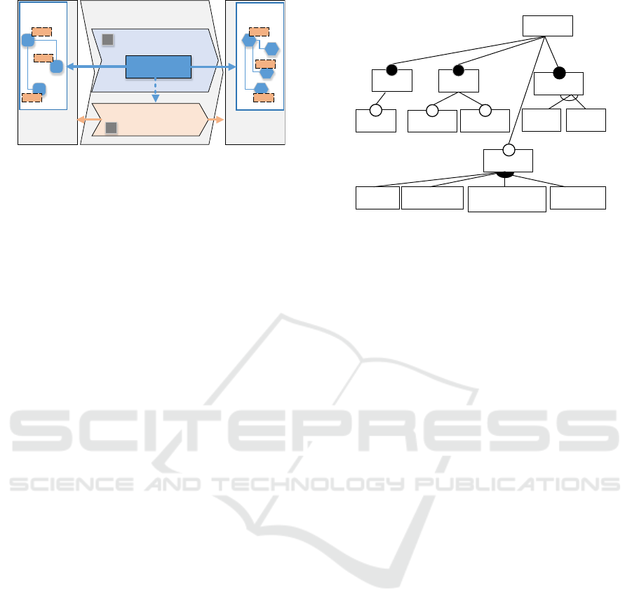
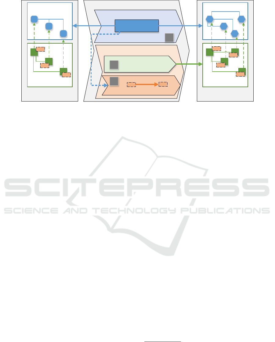
Figure 1: An overview on the contributed solution for
MVMTs. Abbreviation “f.a.” is for “feature annotation”.
so far, these annotations are rather lost than trans-
ferred to the target model. Hence, in order to recover
annotations, workarounds, e.g., copying the annota-
tions manually, are applied. These workarounds are
normally laborious and error-prone, calling for an au-
tomated mechanism to transfer annotations.
Approach. As sate-of-the art SVMT, e.g., ATL,
neglect variability information, multi-variant model
transformations (MVMT) are required for transfer-
ring annotations. Due to the fact that SPLE is based
on the principle of organized reuse, we propose an a
posteriori approach that reuses as many existing tech-
nology as possible without altering it. Thus, at first
the SVMT is reused without modifications to gener-
ate target domain models. As depicted in Figure 1,
annotations are attached to the target model in a sec-
ond step. For automating this task, the artifacts of the
SVMT are analyzed to find corresponding source and
target elements and to propagate annotations corre-
spondingly. The second step is aimed to support dif-
ferent metamodels for source and and target model.
Technical Contribution. While the contributed so-
lution is applicable to MVMT in general, as techni-
cal realization, we decided to use ATL as M2M lan-
guage as well as the MDPLE tool FAMILE (Buch-
mann and Schw
¨
agerl, 2012) to provide source and tar-
get models with product line functionality. In order to
propagate annotations the procedure in Figure 1 is re-
fined. The artifacts are a persisted trace (made avail-
able by the ATL EMFTVM (Wagelaar et al., 2012)
execution engine) and its execution model. After a
non-trivial analysis of these artifacts it is possible to
determine which structural feature of the target was
created from which source element(s). A concrete ex-
ample, in which an Ecore model for a Graph library
is converted into a semantically equivalent UML class
model, serves for motivating and illustrating our ap-
proach as well as for a preliminary evaluation of the
automated propagation.
Nodes
Graph
Edges
Edges
Colored
Directed
Weighted
Search
DFS BFS
Algorithm
Minimum
SpanningTree
Transpose
WeightedthShortestPa
DirectedCycle
DirectedTranspose
Cycle ShortestPath
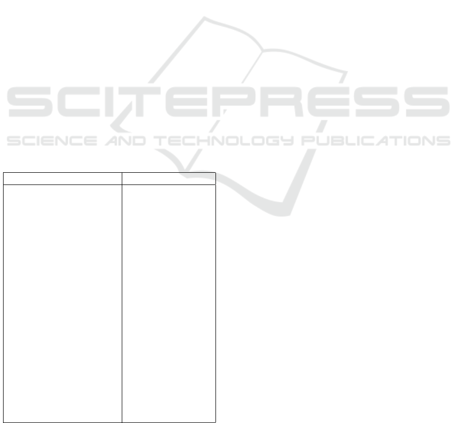
Figure 2: The feature model for the Graph product line,
represented as feature diagram.
Related Work. So far, the field of MVMT is
populated rather sparsely (see Section 6). Sev-
eral approaches support variability in the transforma-
tion specification, e.g., (Sijtema, 2010; Str
¨
uber and
Schulz, 2016). Contrastingly, we address (propagat-
ing) variability of models rather than of transforma-
tion rules. Comparably, in (Salay et al., 2014) an-
notations of model elements are propagated. How-
ever, an MVMT, which is generated from the SVMT,
is executed rather than the SVMT itself. Not only
has it been performed for in-place transformations, in
(Famelis et al., 2015) the lifting algorithm was im-
plemented for a DSL to support a specific out-place
transformation. While the authors require a DSL to
be adapted for the MVMT, we reuse a well-known
SVMT without any modification.
Outline. The next section introduces an example to
illustrate the problem and to detail the key concepts
of our solution. The technical foundations and the re-
alization are described in the following two sections
and will be evaluated in Section 5. Next, we delimit
our approach from related work and draw a conclu-
sion in the last section.
2 MOTIVATING EXAMPLE
This section introduces an example demonstrating the
necessity of a MVMT in a standard SPLE scenario.
2.1 Example Scenario
In the example, we consider a M2M transformation
between an Ecore (Steinberg et al., 2009) and a UML
(Object Management Group, 2015) class model. On
instance level, we use the well-known example of a
Realizing Multi-variant Model Transformations on Top of Reused ATL Specifications
363
SPL for Graph libraries (Lopez-Herrejon and Batory,
2001).
A feature model describing the commonalities
and differences of members of the Graph SPL is
shown in Figure 2. It contains the mandatory features
Graph, Nodes, and Edges; a mandatory Search func-
tion, containing the mutually exclusive features DFS
(depth-first) and BFS (breadth-first search), as well as
different Algorithms, any subset of which can be se-
lected, are provided. The class Cycle keeps track of
its edges and Adajcency lists can be used in the al-
gorithms. Edges may be Weighted and/or Directed.
In addition, there are requires relationships between
different algorithms and other features: Shortest Path
requires the selection of feature Weighted; Cycle and
Transpose both require a Directed graph.
The Ecore-based domain model in its multi-
variant representation, referred to as the source multi-
variant domain model (MVDM), is depicted in Fig-
ure 3. The connection to the feature model is realized
by feature expressions (FE) attached to domain ele-
ments; these annotations determine which (combina-
tion of) features an element realizes.
Table 1 lists a relevant excerpt of the mapping
which attaches annotations to the MVDM elements.
E.g., class Node references a simple list of edges if
not Directed; if feature Directed is selected, this ref-
erence is replaced by two separate lists of incoming
and outgoing edges. One additional mapping for at-
tributes is given for the property weight of the class
Edge (not shown in Table 1, which holds mappings
Table 1: Excerpt of mapping FEs to MVDM elements.
Domain Element Identifier Feature Expression
graph (root package) GraphProductLine
Node
• edges
• inEdges, outEdges
Nodes
• not Directed
• Directed
Color Color
Edge
• weight
• source, target
• nodes
Edges
• Weighted
• Directed
• not Directed
Adjacency, buildAdjList() Search
Cycle Cycle
Search
• bfs()
• dfs()
Search
• BFS
• DFS
Algorithm
• shortestPath(Node, Node)
• minSpanningTree()
• transpose()
Algorithm
• Shortest Path
• Min. Sp. Tree
• Transpose
for domain model elements). Its value for the meta-
attribute derived is true in case the not Weighted vari-
ant is selected; this way, unweighted graphs are in-
ternally mapped to graphs the edges of which have a
weight of 1.
The power of SPLE lies in its ability to gener-
ate customized products (i.e., variants of the domain
model) by configuring the artifacts defined in the plat-
form. The characteristics of a specific product are de-
scribed by a so called feature configuration, which
binds each feature defined in the feature model to
a boolean selection state. For consistency, a fea-
ture configuration is required to comply with all con-
straints (parent/child consistency, mutual exclusion,
requires dependencies) defined in the feature model.
According to the principle of negative variability
(Pohl et al., 2005), a product is derived by filtering
the MVDM using a feature configuration. For this
purpose, the FEs attached to each domain model ele-
ment are evaluated with respect to the boolean bind-
ings specified by the respective feature configuration;
if this yields false, the element is removed from the
product. MDPLE tools such as FAMILE perform this
filter operation automatically.
2.2 The Filter/Transform Dilemma
Returning to the concrete SPLE scenario, during later
development it is required that Ecore models derived
from the product line should be represented as UML
models as UML provides additional modeling con-
structs, e.g., for defining behavior. Assuming that
there exists an (single-variant) M2M transformation
specification which converts a regular Ecore model
to a corresponding UML instance, an initial approach
would apply the transformation repeatedly to all cur-
rently available products of the product line. This cor-
responds with the path filterÑtransform seen in Fig-
ure 4, which comes with major disadvantages. Not
only is it tedious and time-consuming to transform
every product separately, it also contradicts the key
idea of SPLE: organized reuse. In particular, it is de-
sirable to apply the filter operation as late as possible
in order to move as many as possible development ac-
tivities to domain engineering, removing the need to
maintain the products individually and to afterwards
propagate changes back to the platform.
Obviously, the caused effort can be reduced sig-
nificantly by first transforming the MVDM into a
UML-compliant instance and deriving specific UML-
based products thereafter. When considering Fig-
ure 4, the path multi-variant transformÑfilter is
preferable over filterÑtransform. Still, we cannot
simply reuse the existing Ecore to UML transforma-
MODELSWARD 2017 - 5th International Conference on Model-Driven Engineering and Software Development
364
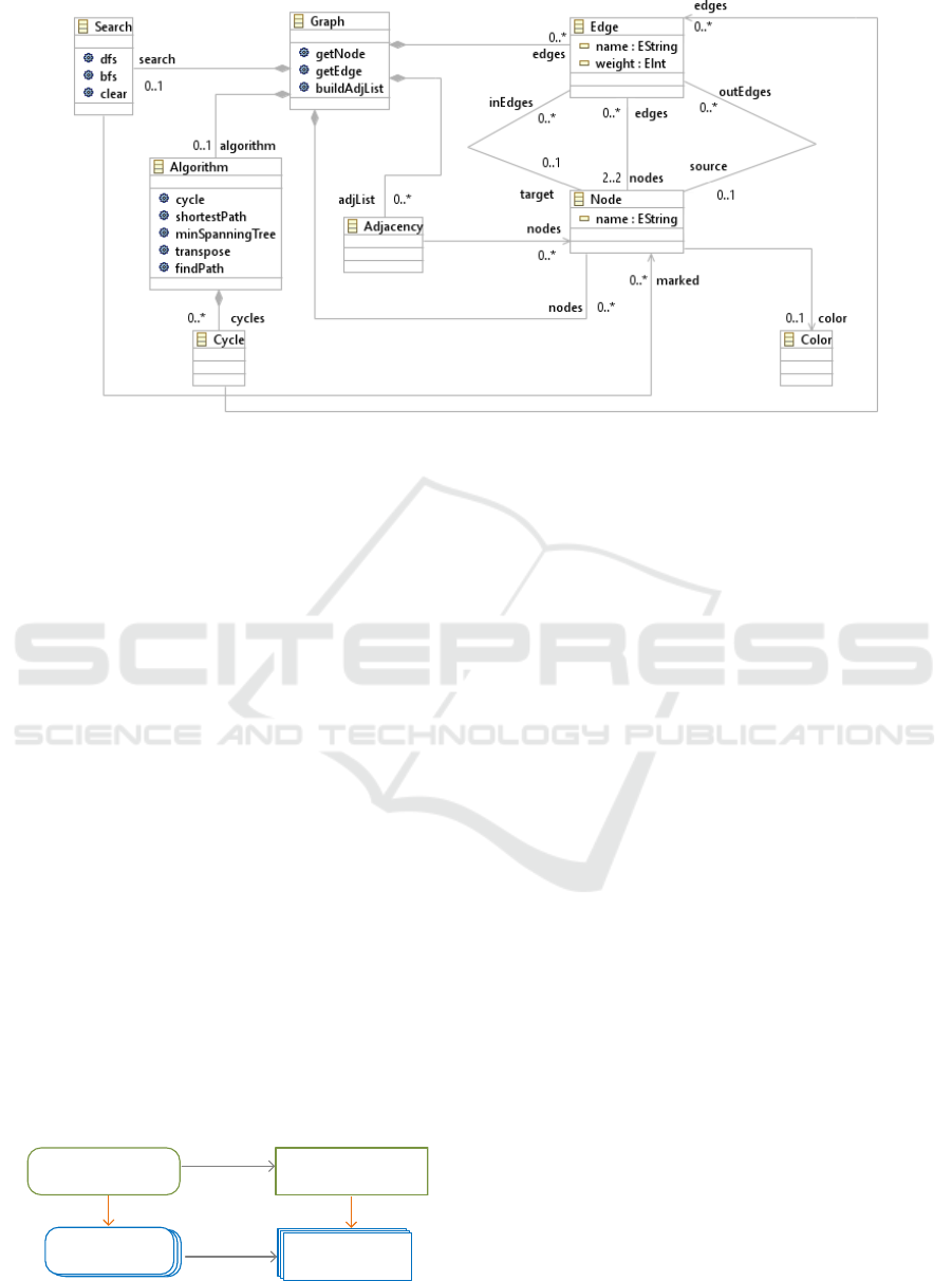
Figure 3: The multi-variant domain model for the graph product line in Ecore class diagram syntax.
tion specification on the source MVDM since anno-
tations (technically, the mapping model) would be ig-
nored. In order to perform the subsequent derivation
step, we would have to (manually) create a mapping
model for the UML instance and to copy the equiva-
lent FE of source elements to their corresponding tar-
get elements. This in turn is even more tedious and
error-prone; after all, the goal of MDSE is to automate
such tasks to the greatest possible extent. It is exactly
this automation that is performed by our MVMT.
2.3 Consequences
To conclude, the example demonstrates three essen-
tial properties an MVMT is supposed to expose: In
order to reduce the manual and error-prone effort
of solving the filter/transformation dilemma, missing
information should be processed (1) automatically
and should (2) reuse an existing single-variant model
transformation specification. In addition, the transfor-
mation should (3) preserve variability.
3 TECHNICAL FOUNDATIONS
To keep this paper self-contained, this section briefly
discusses key technologies employed in our MVMT
Source Multi-Variant
Domain Model
Target Multi-Variant
Domain Model
Source
Products
Single-variant
target models
transform
transform
filter(conf) filter(conf)
Single-variant
target models
Target
Products
multi-variant
Figure 4: Relationship between the two operations filter and
transform in MVMT.
implementation. It introduces the MDPLE environ-
ment FAMILE and an enhanced transformation engine
for ATL that persists trace information.
3.1 FAMILE
The MVMT examined in this paper is situated in the
domain engineering phase of a classical SPLE pro-
cess. The MDPLE tool FAMILE (Buchmann and
Schw
¨
agerl, 2012) is used for SPL management; an-
notations are stored in a separate model, the F2DMM
(feature to domain mapping model), in form of FEs,
boolean expressions that control to which feature a
domain model element belongs.
Due to a distinction between object mappings, at-
tribute mappings, and reference mappings, it is pos-
sible to annotate every EObject as well as each in-
dividual value of its EReferences and its EAttributes
(summarized below as EStructuralFeatures). For in-
stance, the name of an EClass instance may only be
visible for a certain feature otherwise it may remains
empty. Another example has been shown in Sec-
tion 2.1: the value true of the boolean meta-attribute
derived of the Ecore attribute weight of class Edge
is assigned an individual FE. If an explicit value is
missing, the boolean standard value false is assigned
automatically. Elements without FEs are universally
included.
3.2 ATL/EMFTVM
The specification of the domain-level model trans-
formation included in the MVMT problem statement
is written in the well-established unidirectional lan-
guage ATL (Jouault and Kurtev, 2006).
Realizing Multi-variant Model Transformations on Top of Reused ATL Specifications
365
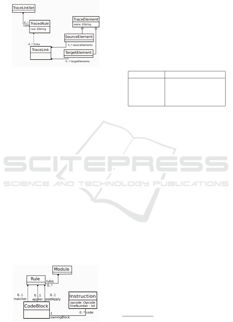
Figure 5: Simplified metamodel of the created trace.
An ATL transformation provides rules where
helpers (either operations or global variables) can be
used. A rule consists of a source pattern (from), a tar-
get pattern (to), where one or more target elements
can be declared, and an optional do-block where fur-
ther assignments or rules may be executed after estab-
lishing the target pattern objects. Three kinds of rules
exist: matched, lazy or called rules. Matched rules
are executed automatically whereas the latter must be
invoked. Matched and lazy rules are accessible in a
volatile trace during execution under certain restric-
tions.
Normally, ATL does not persist traces and the run-
time model of the executed transformation specifica-
tion is removed after compilation. However, in or-
der to reuse the single-variant ATL transformation, we
need to evaluate the ATL rules and the trace a poste-
riori. For that reason, we have employed an extension
to ATL, EMFTVM (EMF transformation virtual ma-
chine) (Wagelaar et al., 2012), that does persist traces.
A trace, schematically depicted in Figure 5, con-
sists of a set of TracedRules which are identified by
the names specified in the transformation specifica-
tion. For every rule application, a TraceLink is cre-
ated that references the source objects and the created
target objects. For instance, the trace of our exam-
ple, applied to the Ecore model (Figure 3), contains
a TraceRule containing eight instances of TraceLinks
each referencing one of the EClasses of the Graph ex-
ample as source and a UML class as target object.
Figure 6: Excerpt from the ATL execution metamodel.
Listing 1: Simple Example for ATL rule.
1 rule Model {
2 from
3 src: Ecore!EPackage (
src.eSuperPackage.oclIsUndefined() )
4 to
5 tar: UML!Model (
6 name <- src.name
7 )
8 }
Table 2: Instructions of applier block for Listing 1.
Instruction Kind Argument
0 LOAD tar:UML!Model
1 LOAD src:Ecore!EPackage
2 GET fieldname: name
3 INVOKE argcount: 0, opname: resolve
4 SET fieldname: name
EMFTVM executes low-level byte code that is
generated during the compilation of the transforma-
tion specification. After compiling the ATL transfor-
mation, this byte code is accessible as EMF model
which we refer to as execution model below. In-
stances of the metaclass Module aggregate rules, oper-
ations and fields, the latter two of which (representing
ATL helpers) are neglected here. A Rule consists of
a matcher, applier, and post-apply code block which
correspond with source and target pattern and the do-
block, respectively. Figure 6 depicts relevant excerpts
of the metamodel. A CodeBlock aggregates a list of
Instructions. These vary by their opcode. In total, 47
different instruction types are defined
1
.
The ATL rule shown in Listing 1, for instance, is
mapped to five instructions in the applier block which
are depicted with their corresponding stack position in
Table 2. First, it LOADs the target UML model (tar),
and second, the source Ecore package (src). Then,
a GET instruction is pushed onto the stack with the
fieldname name, which corresponds with the source
attribute. Next, an INVOKE instruction, which re-
solves the name, is pushed. Finally, the SET instruc-
tion is placed with the fieldname name that corre-
sponds to the target attribute. Further assignments in
the target pattern would each be introduced by at least
one additional LOAD instruction for the target object,
followed by several GET, and terminated by another
SET instruction.
In contrast, since it allows for arbitrary statements,
the do-block might be lacking SET instructions. E.g.,
when only a called rule or a helper is invoked, such
statement is finalized by a POP instruction.
1
http://soft.vub.ac.be/viewvc/*checkout*/EMFTVM/
trunk/emftvm/EMFTVM.html
MODELSWARD 2017 - 5th International Conference on Model-Driven Engineering and Software Development
366
Source Multi-Variant
Domain Model
Mapping Model
Domain Model
Multi-Variant Model Transformation
Source-To-Target Model Transformation
Transformation
Specification
Target Multi-Variant
Domain Model
Mapping Model
Domain Model
input
output
trace + execution model
Variability Information Transfer
Mapping Model
Construction
Feature Expression Transformation
1
2a
2b
Figure 7: An overview on the contributed solution for MVMTs.
4 REALIZATION
As mentioned before, the realized MVMT, sketched
in Figure 7, involves three consecutive steps refining
our general a posteriori approach (Figure 1). First,
the reused ATL transformation is applied to the source
MVDM. Second, the skeleton of the target F2DMM is
built (Step 2a). Third, annotations, in form of FEs, are
transferred from source to target model (Step 2b) by
evaluating the trace and the execution model. Subse-
quently, we describe these steps in greater detail and
reflect on the limitations of the solution. Note that we
do not include the F2DMM transformation in the ATL
specification, as it would contradict the principle of
reuse and would make the MVMT specification tool
and metamodel dependent.
Source-To-Target Model Transformation. First,
the reused M2M transformation is executed. The
source Ecore model is transformed to the target UML
model based on an ATL specification executed with
ATL/EMFTVM. The engine persists a trace and pro-
vides access to the execution model.
Mapping Model Construction. Next, the skeleton
of the mapping model is established for the UML
model by reusing a FAMILE routine that constructs
an F2DMM reflecting the target MVDM and refer-
encing the same feature model as the input F2DMM.
The routine creates an object mapping for every EOb-
ject, an attribute mapping for each EAttribute value
of an object, and a reference mapping for each link
instantiated from an EReference. This way, each ES-
tructuralFeature value of an object in the target do-
main model, may carry an individual FE.
Transfer of Feature Expressions. Still, the target
F2DMM lacks FEs. They are now determined from
the source mapping model (the F2DMM for the Ecore
model). The procedure is composed of two subse-
quent steps. First, expressions of object mappings are
transferred, which is a simple task given that the trace
is available for analysis
2
. Second, expressions for
EStructuralFeatures are considered, which involves a
non-trivial analysis of the opcode of all applied rules.
This is necessary because the trace is maintained on
the level of objects rather than on the (more fine-
grained) level of EStructuralFeature values. Further-
more, the execution model of ATL/EMFTVM is ana-
lyzed rather than the source code, which not accessi-
ble as an EMF model
3
.
4.1 Trace Analysis for Object Mappings
At first, for every object mapping in the target
F2DMM, the corresponding source object is deter-
mined. The realized strategy iterates over the target
F2DMM and searches in the trace a TraceLink which
links the mapped object of the target mapping as one
of its target objects. Then, the source element of the
link is taken to find the corresponding mapping object
in the source F2DMM. If the source mapping contains
an FE, the same expression is attached to the target
mapping. In general, if an FE is missing, the element
is visible in all products. In case of multiple source
elements, their FEs are AND conjuncted as detailed
2
While a rule might reference multiple source objects,
we assume one source object without loss of generality.
Having multiple source objects would result in the same
transfer of annotations as described in Section 4.4.
3
When using the default build, plug-in projects delivered
to the customer only provide the byte code.
Realizing Multi-variant Model Transformations on Top of Reused ATL Specifications
367

in Section 4.4.
Analyzing the trace instead of the execution model
to find corresponding objects offers the benefit that
an evaluation of rule guards in the execution model is
unnecessary. Only objects that match the rule guard
will be persisted in a TraceLink. This information is
exploited in later steps of the transformation.
4.2 Rule Analysis for Detail Mappings
In the next step, mappings for EStructuralFeatures are
processed. Here, the information of the trace is not
sufficient, hence, the execution model must be ex-
ploited. Since it represents compiled byte code, this
model is situated on a quite low level of abstraction.
In order to deduce relevant parts of the originating
ATL rule, we analyze its code blocks and determine
some basic binding and statement patterns that can be
clearly identified . Table 3 lists all currently supported
patterns with corresponding ATL examples and their
EMFTVM opcodes. In the following, the identified
patterns are shortly characterized.
SimpleBindings are the easiest pattern to iden-
tify. One source element is assigned to one target ele-
ment in the output pattern. Details of its opcodes were
shown in the Listing 1 (cf. Table 2).
Another simple instruction block are “hard-
coded” DirectAssignments, in which one or more
constant values which do not refer to features of the
source element(s) are assigned to a target feature.
These instructions always end with a SET command,
mentioning the target element. However, instead of a
GET instruction, a PUSH is placed on the stack.
Furthermore, the procedure identifies Chained-
Gets representing assignments which consist of a path
of values. Such patterns initially LOAD target and
source element. Then, a chain of GET instructions
follows that terminates with a SET instruction. These
instructions always reflect a path of references where
the concluding GET invocation refers to an arbitrary
EStructuralFeature value of the last EObject on the
path. An example is depicted in Table 3, line 3.
In contrast, a CombinedGet involves GET in-
structions that are interrupted by other instructions
before being assigned (SET). For instance, a String
concatenation made up of different attributes is rec-
ognized as such statement. However, if a GET in-
struction is interrupted by an if or for statement or
a method invocation, it will be recognized as an Oth-
erStatement, as is any other statement that cannot be
clearly identified.
Do-blocks. For the instructions in the do-block of
ATL rules, the analysis is more complicated. Here, a
statement does not have to end with a SET instruction.
For instance, if simply a called rule is invoked, no
assignment will take place. Instead of a SET, such
statements are finalized by a POP instruction as seen
in the last line of Table 3.
The procedure that recognizes the code block pat-
terns checks whether a block ends with a SET or a
POP/SET command. Those ending with a POP com-
mand are automatically categorized as OtherState-
ment and, thus, discarded from the feature analysis.
If and for statements are omitted as well since they
might be combined almost arbitrarily in do-blocks.
Memorizing Recognized Patterns. During rule
analysis, recognized patterns are recorded in analyzed
rules, i.e., data structures organizing lists of the afore-
mentioned statement categories. Our procedure splits
up the whole instruction set of the to-pattern (applier)
and the do-block (post-apply) in blocks of the sin-
gle statement kinds and adds the blocks to a respec-
tive list. For instance, the analyzed rule of the ATL
rule shown in Listing 2 holds three SimpleBindings
for line 6-8 and one for line 16. Lines 11-12 repre-
sent a CombinedGet whereas line 13 and 15 are each
evaluated as ChainedGet. The remaining bindings are
recognized as DirectAssignments.
Listing 2: ATL rule that creates a unidirectional association.
1 rule Reference2UniAssoc {
2 from src: Ecore!EReference
3 ( src.eOpposite.oclIsUndefined() )
4 to
5 tar: UML!Property (
6 name <- src.name,
7 type <- src.eType,
8 upper <- src.upperBound,
9 association <- tar1 ),
10 tar1: UML!Association (
11 name <- src.name + ’To’ +
12 src.eContainingClass.name,
13 package <-
src.eContainingClass.ePackage),
14 tar2: UML!Property (
15 name <- src.eContainingClass.name,
16 type <- src.eContainingClass,
17 upper <- 1,
18 association <- tar1,
19 owningAssociation <- tar1
20 )
21 }
4.3 Extracting Relevant Mappings
After having analyzed the statements inside the trans-
formation rules, the identified patterns are used to
determine matching EStructuralFeature values from
transformed EObjects. Their FEs are supposed to be
MODELSWARD 2017 - 5th International Conference on Model-Driven Engineering and Software Development
368
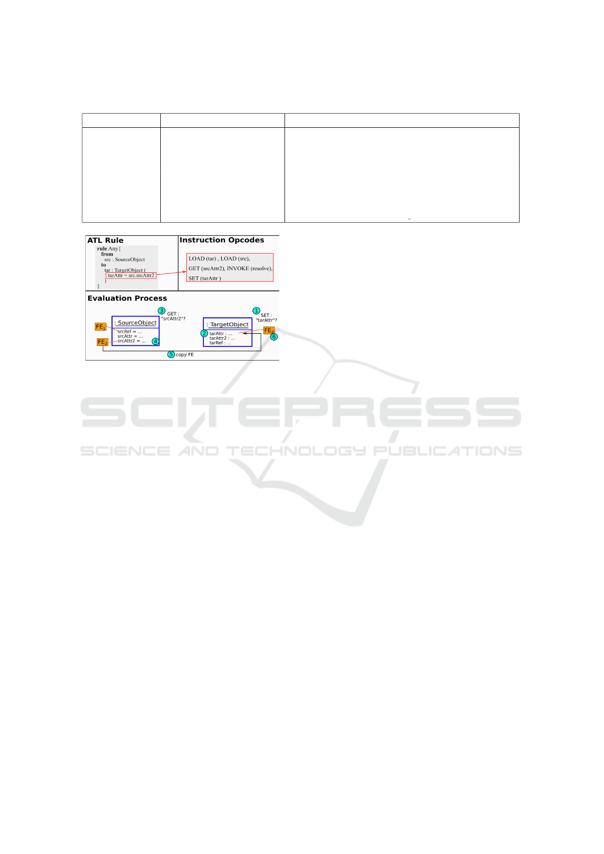
Table 3: Identified code block patterns and corresponding lists of opcode-level instructions.
Identified Pattern ATL Example Corresponding Opcodes
SimpleBinding name Ð src.name LOAD(tar), LOAD(src), GET, INVOKE, SET
DirectAssignment name Ð ’Hardcoded Name’ LOAD, PUSH, INVOKE, SET
ChainedGet name Ð src.ePackage.name LOAD, LOAD, GET, GET, INVOKE, SET
CombinedGet name Ð src.name + ” ” +
src.ePackage.name
LOAD, LOAD, GET, PUSH, LOAD, GET, GET, INVOKE, SET
OtherStatement if (ref.eOpposite) LOAD, GET, INVOKE, IFN
thisModule.createAssoc(ref) GETENVTYPE, LOAD, INVOKE STATIC, POP
Figure 8: Example procedure to transfer an FE.
propagated from source to target F2DMM. For this
purpose, the source objects are examined for a syntac-
tical match of their EStructuralFeatures with the name
specified in the GET instructions.
First, the procedure searches matches of the E-
StructuralFeature names of all target objects in the
statements of the analyzed rule: The name declared
in the SET instruction must match the name of the
target EStructuralFeature. If so, the GET fields of this
statement come into play. The corresponding source
object is analyzed whether the name of one of its ES-
tructuralFeatures matches the name of the GET field.
Only then an FE attached to the corresponding source
EStructuralFeature is transferred from source to target
mapping.
Figure 8 sketches the procedure of finding corre-
sponding FEs. On top, a simple rule and its opcodes
are shown. The rule is classified as SimpleBinding in
our pattern matching strategy. Note that the F2DMMs
and their mappings are omitted from the figure: FEs
are attached to their attributes directly in order to re-
duce complexity. In this example, the attribute tarAttr
is identified to match with the name specified in the
SET instruction (Steps 1 and 2). As a match is found,
the EStructuralFeatures of the source object are ex-
amined for a match with the GET field (Steps 3 and
4), srcAttr2 in the example. Since the corresponding
mapping has an FE attached, the FE is copied to the
target attribute and attached there (Steps 5 and 6).
Identifying the GET field in question is trivial for
SimpleBindings (as there is only one) but more com-
plex for Chained or CombinedGets. Both resemble a
path of references that must be followed before deter-
mining the FE; e.g., in Table 3, an FE attached to the
ePackage and an FE of the package’s name are both
copied to the target attribute. This leads to the ques-
tion how to proceed with target mappings to which
multiple FEs need to be assigned.
4.4 Combining Feature Expressions
Considering the transfer of FEs, the procedure is the
same for object and attribute or reference mappings.
With 1:1 and 1:n creations the source FE can be
copied to the target element(s). If one element is cre-
ated from many source elements (n:1), determining
the adequate FE for the target appears more complex.
To the best of our knowledge, we assume that a single
target element will only exist if all its source elements
are present. Accordingly, all source FEs must evalu-
ate positively for the target element to be present. This
is why our procedure attaches the AND conjunction of
all source FEs.
4.5 Limitations
We conclude the presentation of the MVMT solu-
tion by a reflection on its currently implied limitations
resulting from difficulties determining matching fea-
tures automatically.
As it can be seen in Table 3, only some syntactical
constructs can be identified during byte code analy-
sis. Everything categorized as OtherStatement signi-
fies parts in the transformation which can hardly be
evaluated automatically and involve complex strate-
gies for their analysis. Accordingly, the success and
runtime of the overall management of FEs depends
on the complexity of the ATL transformation. If only
SimpleBindings were allowed, the analysis would be
rather simplistic. On the contrary, helpers, called
rules and if or for statements make it hard to guaran-
tee that the values of corresponding EStructuralFea-
tures are correctly matched. As a consequence, the
Realizing Multi-variant Model Transformations on Top of Reused ATL Specifications
369

base ATL transformation should be kept as simple as
possible to allow a fast and correct execution.
Altogether, the automatic propagation of FEs con-
stitutes a heuristic which is not guaranteed to always
deliver the expected result. Nevertheless, the evalua-
tion given in the next section indicates a high accuracy
of the propagation in practice.
5 EVALUATION
The added value of our MVMT solution is obvi-
ous: It allows to transfer variability information
alongside with domain models when being applied
to ATL model transformations, obviating the need
for repeated application of the reused (single-variant)
model transformation (SVMT). In order to be pur-
poseful, three criteria remain to be evaluated:
1. The user effort required for the invocation of the
MVMT should be less when compared to the
straightforward approach of manually transferring
annotations from the source to the target MVDM.
2. The runtime needed for the execution of the
MVMT should be at least in the same magnitude
as the SVMT repeatedly applied to each product.
3. Products derived after the application of the
MVMT should resemble the state-of-the-art ap-
proach of transforming each product individually
with the highest possible accuracy. Thus, the dia-
gram depicted in Figure 4 must commute.
We conducted a quantitative evaluation referring
to the Graph example introduced in Section 2.1. Here,
we describe the methodology used and present the re-
sults that, taken together, state that all three evaluation
criteria are fulfilled.
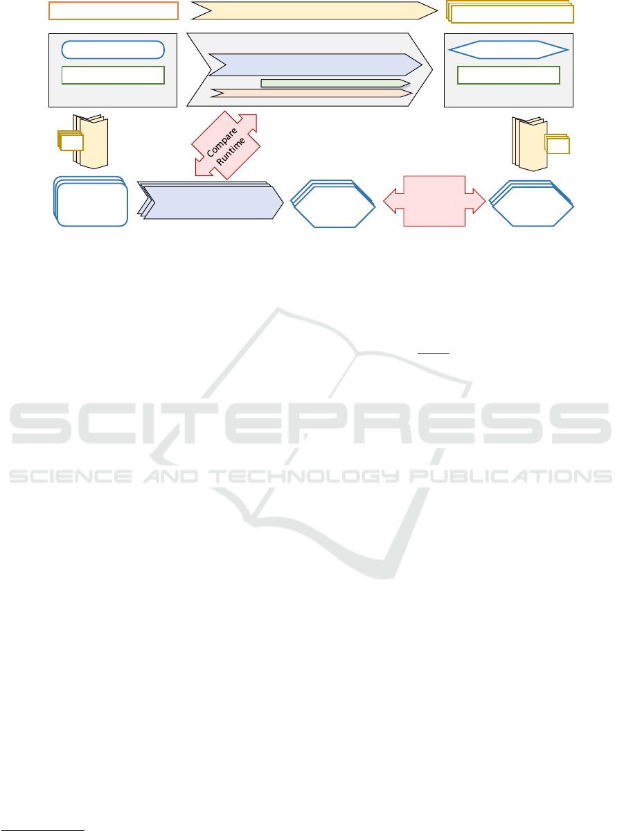
5.1 Methodology
The employed methodology is outlined in Figure 9;
the entire procedure has been implemented in a
single-threaded evaluation program written in Java.
First, ensuing from the feature model, a brute-force
procedure is applied to generate all valid feature con-
figurations, the number of which is referred to as n
subsequently. After that, both the contributed MVMT
and the state-of-the-art solution, the repeated applica-
tion of a SVMT, run in competition on the two fol-
lowing execution branches:
MVMT. The source MVDM, consisting of the Ecore-
based domain model (cf. Figure 3) and the map-
ping model (cf. excerpt in Table 1) are passed to
the MVMT solution described in Section 4. The
result is a target MVDM, consisting of a UML-
based domain model and a corresponding map-
ping model. Notice that the realized MVMT in-
cludes a single run of the reused SVMT (cf. Fig-
ure 7). Next, the procedure iterates over all n
valid feature configurations calculated before and
derives a specific UML-based target product for
each. The results are aggregated in a collection of
size n of MVMT target products.
Repeated SVMT. From the source MVDM, all pos-
sible source products are derived by filtering by
all n valid feature configurations in a loop. The in-
termediate result is a collection of n Ecore-based
source products. Thereafter, the procedure iter-
ates over all source products and applies the same
Ecore to UML model transformation that has been
reused by the MVMT. The result is a collection of
n SVMT target products, which all conform to the
UML metamodel.
The quantities referred to above are then extracted
from a comparison of the two competing solutions,
MVMT versus repeated SVMT.
The user effort saved can be estimated from the
number of automatically generated FEs in the target
MVDM.
The runtime of the single MVMT run performed
in the first branch is compared to the aggregated run-
time of all SVMT runs in the second branch. For bet-
ter accuracy, the MVMT is repeated 20 times; the best
five and the worst five results are omitted when calcu-
lating the average runtime of the remaining ten runs.
For quantifying accuracy, each MVMT tar-
get product is differentiated with its corresponding
SVMT target product generated for the same feature
configuration. For the comparison, we use the match-
ing engine EMF Compare
4
(Brun and Pierantonio,
2008) in version 3.1.1. The number of differences
(i.e., element insertions, modifications or removals)
detected by EMF Compare is recorded for each of the
n product variants. The corresponding edit similarity
may then be calculated as the quotient of the numbers
of non-modified and overall model elements.
5.2 Key Figures and Results
The results of the evaluation run claim a reduced user
effort. Furthermore, they indicate a runtime improve-
ment of approximately factor 9 and an accuracy of
4
EMF Compare offers several comparison strategies, in-
cluding object comparison by properties or by UUID (a
universally unique identifier assigned to each object af-
ter creation). Since the transformations produce equiva-
lent elements carrying different UUIDs, we chose a purely
property-based matching strategy.
MODELSWARD 2017 - 5th International Conference on Model-Driven Engineering and Software Development
370
Source MVDM
Mapping Model
Domain Model
Multi-Variant Model Transformation
Source-To-Target Model Transformation
Target MVDM
Mapping Model
Domain Model
Feature Model
Feature Configurations
Generate all valid configurations
Feature Configurations
Feature Configurations
Source-To-Target Model
Transformation
Source-To-Target Model
Transformation
Source-To-Target Model
Transformation
Derive
Derive
Filter
Derive
Derive
Filter
Source
Products
Source
Products
SVMT
Source
Products
Source
Products
Source
Products
SVMT
Target
Products
Source
Products
Source
Products
MVMT
Target
Products
Differentiate
(EMF
Compare)
Figure 9: Applied evaluation methodology for measuring the runtime and the accuracy of the MVMT.
100% for MVMT when compared to repeated SVMT.
Detailed quantities are given below.
Input. The Ecore-based source MVDM comprises
49 model objects (packages, classes, attributes, refer-
ences, operations, and parameters; see Figure 3).
The feature model contains 14 features, eleven of
which are optional (cf. Figure 2). Out of 2
11
“ 2048
possible variants, n :“ 180 accord to the constraints
of the feature model (parent/child and group con-
straints, requires/excludes relationships). The map-
ping model assigns 34 feature expressions to elements
of the source MVDM (cf. excerpt in Table 1).
User Effort. By the reused transformation, a target
multi-variant UML model was generated that consists
of 130 objects (classes, properties, associations, oper-
ations, parameters, and values).
In the course of the MVMT, a target F2DMM was
created referencing the same feature model as the in-
put F2DMM. The number of FEs transferred was 62.
Taken together, the user effort (cf. evaluation cri-
terion (1)) is significantly reduced when compared to
a manual transfer of variability information.
Runtime. All runtime measurements have been
performed on a machine with 2.60GHz Intel Core i7
CPU
5
and 8GB memory.
We averaged the MVMT runtime using 20 (and ef-
ficiently measuring ten) iterations as described above,
resulting in a runtime of 482 milliseconds. The run-
time of individual iterations (after omitting the best
and worst 25%) was in between 415ms and 574ms,
respectively.
5
Since the evaluation program is single-threaded, the
number of cores (8) is irrelevant.
The repeated SVMT branch took a total computa-
tion time of 4230 milliseconds for all 180 variants.
Individual transformation runs consumed between
13.6 and 73.9 milliseconds; average was 23.5ms.
In total, these figures result in a runtime improve-
ment of factor
4230ms
482ms
“ 8.776. This indicates that
evaluation criterion (2) is overfulfilled.
Accuracy. Each comparison between the target
products derived by the SVMT and the MVMT
branch yielded an accuracy of 100%, meaning that not
a single difference was identified by EMF Compare.
Thus, we fulfill evaluation criterion (3) to our full sat-
isfaction. When referring to Figure 4, this reveals
that the operations (multi-variant) transform and fil-
ter commute in this specific evaluation scenario.
5.3 Threats to Validity
The investigated scenario is based on specific input
on metamodel level (Ecore and UML) as well as on
model instance level (Graph example). Results, may
vary for other inputs. Although the presented exam-
ple provides an accuracy of 100%, we cannot provide
a general proof for commutativity of transform and
filter.
Furthermore, the case study is rather simplistic.
The metamodels of Ecore und UML share a large
amount of similarities. The instance-level example is
an “academic” product line having only eleven fea-
tures and allowing 180 variants.
Last, the here considered ATL transformation has
been specified in consciousness of the limitations re-
ferred to in Section 4.5. In real-world applications,
more advanced ATL syntax, which is currently not
supported in our MVMT, may be necessary.
Realizing Multi-variant Model Transformations on Top of Reused ATL Specifications
371

6 RELATED WORK
For a general literature review concerning the prob-
lem statement of MVMT, we refer to (Schw
¨
agerl
et al., 2016). In this section, we first outline solutions
to similar versions of the here considered MVMT
problem. Then, we discuss similar technical solutions
where the problem statement, however, differs from
the case considered here, since variability lies in the
transformation itself rather than in the input/output.
Multi-variant Model Transformations. In (Salay
et al., 2014), a lifting algorithm is presented which
applies existing graph transformation rules to a model
that contains variability. In contrast to our solution,
which has been designed for exogenous out-place
transformations, the rules considered by the lifting
algorithm describe endogenous in-place transforma-
tions. As another difference, rather than actually ex-
ecuting the reused single-variant transformation and
analyzing its artifacts, the lifting algorithm produces
a multi-variant transformation where, e.g., application
conditions (which correspond to guards in ATL) are
interpreted with multi-variant semantics.
The implementation is based on the graph trans-
formation engine Henshin (Arendt et al., 2010). Ex-
ternally, variability is defined by means of a feature
model; the connection to the domain model is created
in the form of presence conditions physically attached
to the model objects; this is opposed to the mapping
model approach used here, which also allows to map
individual values of EStructuralFeatures. Thus, our
approach supports a higher granularity of variability.
Likewise, the lifting algorithm has been applied to
an exogenous out-place transformation based on the
graph-rewriting language DSLTrans (Famelis et al.,
2015). To lift the transformation, the DSLTrans en-
gine has to be adapted for the specific input and output
metamodels. Contrastingly, our approach does not re-
quire any scenario-specific modifications towards the
ATL engine, since it supports arbitrary metamodels as
in- and output of exogenous out-place MVMTs.
Variability in Rules. Our approach aims to reuse
single-variant transformation specifications. A larger
body of related work focuses on reusing model
transformation languages by extending them for
variability-aware rules.
In (Sijtema, 2010), a compositional approach to
ATL specifications is described. The authors intro-
duce new syntactical constructs which are maintained
in a higher-order transformation. Feature annotations
may be included in the source model. With our ap-
proach, however, no special ATL syntax must be used;
rather, a single-variant transformation can be reused.
Moreover, the variability information is conceptually
and physically separated from the domain model.
An approach that explicitly uses variability-aware
rules is proposed in (Str
¨
uber and Schulz, 2016) as an-
other tool extension to Henshin (Arendt et al., 2010)
allowing filtered editing on the rules. It reduces
the cognitive complexity when developing variational
graph transformation rules. Nonetheless, variability
must be expressed explicitly whereas our approach
reuses existing single-variant M2M transformations.
Bent
¯
o (Cuadrado et al., 2014) is another approach
to the reuse of model transformations. It employs
generic rules for similar ATL transformations to make
them executable based on different metamodels. The
user needs to provide a concept, describing the source
metamodel, and a binding from which the generic
ATL template is automatically adapted to perform the
specific model transformation. The approach involves
a static analysis of the ATL rules for binding the types.
However, variability in the input is not foreseen.
7 CONCLUSION
This paper has presented an approach to realize a
multi-variant model transformation by reusing ex-
isting single-variant model transformation specifica-
tions. Due to an a posteriori analysis of the transfor-
mation artifacts, it is possible to transfer variability
annotations in an automated way independent of the
input. While comparable approaches are applicable
to graph-rewriting formalisms only – even requiring
to adapt the underlying SVMT engines –, we do not
infer in the SVMT. To the best of our knowledge, this
approach supports the most general scenarios of ex-
ogenous out-place MVMT.
An evaluation based on the example scenario in-
dicates considerable reduction of the required user
effort as transformations are already applied at the
stage of domain engineering rather than during ap-
plication engineering. Furthermore, the evaluation
showed considerable runtime savings and the high-
est possible accuracy of 100% when compared to ar-
tifacts obtained from repeated SVMT execution.
Future work involves a general examination of ap-
plying annotations to target elements and research on
generalizing the approach.
REFERENCES
Arendt, T., Biermann, E., Jurack, S., Krause, C., and
Taentzer, G. (2010). Henshin: advanced concepts and
MODELSWARD 2017 - 5th International Conference on Model-Driven Engineering and Software Development
372

tools for in-place emf model transformations. In In-
ternational Conference on Model Driven Engineering
Languages and Systems, pages 121–135. Springer.
Brun, C. and Pierantonio, A. (2008). Model differences
in the eclipse modelling framework. UPGRADE,
IX(2):29–34.
Buchmann, T. and Schw
¨
agerl, F. (2012). FAMILE: tool
support for evolving model-driven product lines. In
St
¨
orrle, H., Botterweck, G., Bourdells, M., Kolovos,
D., Paige, R., Roubtsova, E., Rubin, J., and Tolvanen,
J.-P., editors, Joint Proceedings of co-located Events
at the 8th ECMFA, CEUR WS, pages 59–62, Building
321, DK-2800 Kongens Lyngby. Technical University
of Denmark (DTU).
Cuadrado, J. S., Guerra, E., and de Lara, J. (2014). A com-
ponent model for model transformations. IEEE Trans-
actions on Software Engineering, 40(11):1042–1060.
Famelis, M., L
´
ucio, L., Selim, G., Di Sandro, A., Salay, R.,
Chechik, M., Cordy, J. R., Dingel, J., Vangheluwe, H.,
and Ramesh, S. (2015). Migrating automotive product
lines: a case study. In International Conference on
Theory and Practice of Model Transformations, pages
82–97. Springer.
Gomaa, H. (2004). Designing Software Product Lines with
UML: From Use Cases to Pattern-Based Software Ar-
chitectures. Addison-Wesley, Boston, MA.
Jouault, F. and Kurtev, I. (2006). Transforming mod-
els with atl. In Proceedings of the 2005 Interna-
tional Conference on Satellite Events at the MoD-
ELS, MoDELS’05, pages 128–138, Berlin, Heidel-
berg. Springer-Verlag.
Lopez-Herrejon, R. E. and Batory, D. S. (2001). A stan-
dard problem for evaluating product-line methodolo-
gies. In Proceedings of the Third International Con-
ference on Generative and Component-Based Soft-
ware Engineering, GCSE ’01, pages 10–24, London,
UK. Springer.
Mellor, S. J., Kendall, S., Uhl, A., and Weise, D. (2004).
MDA Distilled. Addison Wesley Longman Publishing
Co., Inc., Redwood City, CA, USA.
Object Management Group (2015). Documents Associated
With Unified Modeling Language (UML), Version 2.5.
Needham, MA.
Pohl, K., B
¨
ockle, G., and van der Linden, F. (2005). Soft-
ware Product Line Engineering: Foundations, Princi-
ples and Techniques. Springer, Berlin, Germany.
Salay, R., Famelis, M., Rubin, J., Sandro, A. D., and
Chechik, M. (2014). Lifting model transformations
to product lines. In 36th International Conference on
Software Engineering, ICSE ’14, Hyderabad, India -
May 31 - June 07, 2014, pages 117–128.
Schw
¨
agerl, F., Buchmann, T., and Westfechtel, B. (2016).
Multi-variant model transformations — a problem
statement. In Maciaszek, L. and Filipe, J., editors,
Proceedings of the 11th International Conference on
the Evaluation of Novel Approaches to Software Engi-
neering (ENASE 2016), Rome, Italy. SCITEPRESS.
Sijtema, M. (2010). Introducing variability rules in atl
for managing variability in mde-based product lines.
Proc. of MtATL, 10:39–49.
Steinberg, D., Budinsky, F., Paternostro, M., and Merks,
E. (2009). EMF Eclipse Modeling Framework. The
Eclipse Series. Boston, MA, 2nd edition.
Str
¨
uber, D. and Schulz, S. (2016). A Tool Environment for
Managing Families of Model Transformation Rules,
pages 89–101. Springer International Publishing,
Cham.
V
¨
olter, M., Stahl, T., Bettin, J., Haase, A., and Helsen, S.
(2006). Model-Driven Software Development: Tech-
nology, Engineering, Management. John Wiley &
Sons.
Wagelaar, D., Iovino, L., Di Ruscio, D., and Pierantonio,
A. (2012). Translational semantics of a co-evolution
specific language with the emf transformation virtual
machine. In International Conference on Theory and
Practice of Model Transformations, pages 192–207.
Springer.
Realizing Multi-variant Model Transformations on Top of Reused ATL Specifications
373
