
Simultaneous Camera Calibration and Temporal Alignment of 2D and
3D Trajectories
Joni Herttuainen, Tuomas Eerola, Lasse Lensu and Heikki K
¨
alvi
¨
ainen
Machine Vision and Pattern Recognition Laboratory, School of Engineering Science,
Lappeenranta University of Technology, P.O. Box 20, 53851, Lappeenranta, Finland
joni.herttuainen@student.lut.fi, {tuomas.eerola, lasse.lensu, heikki.kalviainen}@lut.fi
Keywords:
Trajectory Alignment, Camera Calibration.
Abstract:
In this paper, we present an automatic method that given the 2D and 3D motion trajectories recorded with a
camera and 3D sensor, automatically calibrates the camera with respect to the 3D sensor coordinates and aligns
the trajectories with respect to time. The method utilizes a modified Random Sample Consensus (RANSAC)
procedure that iteratively selects two points from both trajectories, uses them to calculate the scale and transla-
tion parameters for the temporal alignment, computes point correspondences, and estimates the camera matrix.
We demonstrate the approach with a setup consisting of a standard web camera and Leap Motion sensor. We
further propose necessary object tracking and trajectory filtering procedures to produce proper trajectories
with the setup. The result showed that the proposed method achieves over 96% success rate with a test set of
complex trajectories.
1 INTRODUCTION
The motivation for this work comes from the human-
computer interaction (HCI) research where exists a
need to accurately record natural hand and finger
movements of test subjects in various HCI tasks. Ad-
vances in gesture interfaces, touchscreens, augmented
and virtual reality bring new usability concerns that
need to be studied when using them in natural en-
vironment and in an unobtrusive way. Several ro-
bust approaches for hand tracking exist, such as data
gloves with electromechanical or magnetic sensors
that can measure the hand and finger location with
high accuracy. However, such devices affect the nat-
ural hand motion and cannot be considered a feasi-
ble solution when pursuing natural HCI. As a conse-
quence, there is a need for image-based solutions that
provide an unobtrusive way to study and track human
movement and enable natural interaction with tech-
nology.
Modern digital cameras make it possible to study
object trajectories with high accuracy and also with
high frame rate, and state-of-the-art object trackers
provide robust and fast tools to construct the motion
trajectories automatically from the videos. For exam-
ple, in (Hiltunen et al., 2014), several object track-
ing methods were compared with high-speed videos
and the top methods were found to be suitable for
the problem of measuring HCI. In (Kuronen et al.,
2015), the tracking was supplemented with filtering
techniques to provide a methodology to measure and
study 2D hand motion of test subjects performing var-
ious HCI tasks.
Typically, the real motion trajectories are in 3D,
but recording accurate 3D trajectories would require
multiple high-speed cameras. Such measurement
setup is both expensive and difficult to build. On
the other hand, 3D sensors, such as Leap Motion or
Kinect, do not allow high frame rates and lack the
versatility and debuggability of a camera based sys-
tem. A setup consisting of a single high-speed cam-
era accompanied with a separate 3D sensor to capture
depth information provides an affordable alternative
that produces reasonably accurate trajectories.
In this work, we propose a method to automati-
cally calibrate the camera with respect to 3D sensor
coordinates and temporally align 2D and 3D trajec-
tories, i.e., given a point in time, the location of the
object can be obtained in both image and 3D sensor
coordinates (see Fig. 1). By camera calibration we
mean determining the mapping from 3D sensor coor-
dinates to 2D image coordinates, i.e., estimating the
camera matrix. The method requires only the tracked
2D and 3D trajectories, and no temporal synchroniza-
tion of the devices is needed as long as the trajectories
are at least partially overlapping with respect to time.
Herttuainen J., Eerola T., Lensu L. and KÃd’lviÃd’inen H.
Simultaneous Camera Calibration and Temporal Alignment of 2D and 3D Trajectories.
DOI: 10.5220/0006126304450450
In Proceedings of the 12th International Joint Conference on Computer Vision, Imaging and Computer Graphics Theory and Applications (VISIGRAPP 2017), pages 445-450
ISBN: 978-989-758-227-1
Copyright
c
2017 by SCITEPRESS – Science and Technology Publications, Lda. All rights reserved
445

2D trajectory obtained
from a camera video
3D trajectory
Aligned trajectories
projected into 2D
Figure 1: Alignment of 2D and 3D trajectories.
Although the motivation for the work comes partly
from high-speed imaging, in the experimental part of
the work, the method is demonstrated using standard
frame rate videos mainly due to computational issues.
However, the method does not make any assumptions
about frame rates and can be straightforwardly gener-
alized to high-speed videos with increase in computa-
tion time being the only downside.
2 RELATED WORK
Camera auto-calibration is a widely studied
topic (Triggs, 1998; Sturm, 2000; Zhao and Lv,
2012; Liu et al., 2003; El Akkad et al., 2014). The
aim is to calibrate the camera, i.e., determine the
camera parameters from multiple images of an arbi-
trary scene without any calibration target or object.
The basic idea is to use image point correspondences
between the images with different views to estimate
the intrinsic and extrinsic camera parameters, and
to reconstruct 3D structure of a scene. In addition,
single image auto-calibration techniques do exist.
For example, in (Wu et al., 2007), a method to
estimate camera parameters from a single image
using vanishing points and RANSAC algorithm was
proposed. In (Rahimi et al., 2004), a method to
automatically calibrate cameras in a multi-camera
system based on object trajectories was presented.
However, the method requires synced cameras and
the problem of temporal alignment of the trajectories
was not considered.
Various methods are available for temporal align-
ment and fusion of 2D and 3D trajectories. In (Ran-
garajan et al., 1993), a method to match 2D trajec-
tories with 3D trajectories using scale-space repre-
sentations was presented. In (Knoop et al., 2009),
an iterative closest point (ICP) based method was
proposed to fuse 2D and 3D sensor data for human
motion capture. In (Caspi and Irani, 2000), an ap-
proach to align two image sequences using both spa-
tial and temporal information available within the se-
quence was presented. Besides the last method that
only considers 2D trajectories, all the methods re-
quire a precalibrated setup. In (Noguchi and Kato,
2007), a method that simultaneously finds the lag in
shutter timing between unsynchronized cameras and
calibrates the cameras was proposed. However, the
method assumes that the sensors (cameras) have the
same frame rate which often is not the case in sys-
tems consisting of multiple types of sensors (e.g. a
camera and 3D sensor). To the best of our knowl-
edge, no method exist to simultanously align 2D and
3D trajectories with an arbitrary delay and frame rates
and to calibrate the camera with respect to the 3D co-
ordinates.
3 PROPOSED METHOD
Our method is inspired by the Random Sample Con-
sensus (RANSAC) algorithm (Fischler and Bolles,
1981). Given 2D and 3D trajectories consisting
of sets of points (T
2D
= {p
1
, p
2
, ..., p
M
}, T
3D
=
{q
1
, q
2
, ..., q
L
}), the method starts by selecting two
random points from both trajectories ({p
k1
, p
k2
} and
{q
l1
, q
l2
}, respectively). These points are assumed to
represent the same moment in time, and based on this
assumption, a temporal alignment between the two
trajectories is made. That is, the delay (t
t
) and ratio
of frame rates (s
t
) are computed as
s
t
=
k
2
− k
1
l
2
− l
1
t
t
= k
1
− s
t
l
1
,
(1)
where k
1
and k
2
are the indices of the selected random
points in the 2D trajectory and l
1
and l
2
are the point
indices in the 3D trajectory.
Based on the alignment parameters ({t
t
, s
t
}), a
corresponding point for each point in the 2D trajec-
tory (T
2D
) is computed from the 3D trajectory (T
3D
)
using linear interpolation resulting a new 3D trajec-
tory (
˜
T
3D
= {
˜
q
1
,
˜
q
2
, ...,
˜
q
L
}) with the same number of
points as in the 2D trajectory. N (N ≥ 6) random point
correspondences, i.e., {p
k
,
˜
q
k
} pairs are then selected
from the trajectories. These point correspondences
are used to estimate the camera matrix
M =
m
1,1
m
1,2
m
1,3
m
1,4
m
2,1
m
2,2
m
2,3
m
2,4
m
3,1
m
3,2
m
3,3
m
3,4
(2)
using a linear least squares algorithm with an extra
restriction of m
1,1
= 1 to avoid the trivial solutions
VISAPP 2017 - International Conference on Computer Vision Theory and Applications
446

(m
i, j
= 0 for all i = 1, 2, 3 and j = 1, 2, 3, 4) (Abdel-
Aziz, 1971; Heikkila and Silv
´
en, 1997). Also New-
ton’s method was tested to further optimize the solu-
tion, but since it increased the computation time and
did not significantly improve the results, it was not
used in the experimental part of the work.
In each iteration, the goodness (optimization cri-
terion) of the estimated camera matrix is computed.
Two different optimization criteria were considered.
The first one is similar to the RANSAC algorithm.
All the points in the trajectory
˜
T
3D
are reprojected into
2D using the camera matrix M resulting a 2D trajec-
tory
˜
T
2D
= {
˜
p
1
,
˜
p
2
, ...,
˜
p
M
}. Next, the Euclidean dis-
tance between each point in the 2D trajectory (T
2D
)
and corresponding point in the reprojected 3D trajec-
tory (
˜
T
2D
) are computed as
d
i
=
q
(p
i,1
− ˜p
i,1
)
2
+ (p
i,2
− ˜p
i,2
)
2
(3)
The first optimization criterion (Criterion 1) is de-
fined as the number of inliers, i.e., points for which
the Euclidean distance is smaller than threshold τ:
g =
M
∑
i=1
x
i
, (4)
where
x
i
=
0, d
i
> τ
1, d
i
< τ
(5)
The second optimization criterion (Criterion 2) is
computed as the mean Euclidean distance over all
points in T
2D
:
g =
1
M
M
∑
i=1
d
i
. (6)
The above steps are iteratively repeated for a pre-
defined number of times, and finally the best camera
matrix is selected based on the chosen optimization
criterion with the corresponding alignment parame-
ters. The whole algorithm is summarized in Algo-
rithm 1.
4 EXPERIMENTS
4.1 Experimental Arrangements
The 3D trajectories of the index finger of a human
hand and a pencil were recorded using a Leap Motion
sensor
1
. A fixed frame rate of 50 fps was used instead
of the default varying frame rate. It was noted that, at
times, the Leap Motion lost the track of the finger or
pencil giving no coordinates for individual points. For
1
https://www.leapmotion.com/
Algorithm 1: Simultaneous camera calibration and temporal
alignment.
1: Input: 2D trajectory (T
2D
) and 3D trajectory
(T
3D
)
2: Output: frame rate ratio s
t
, delay t
t
, and esti-
mated camera matrix
ˆ
M
3: while iteration < k do
4: Randomly select point pairs {p
k1
, p
k2
} and
{q
l1
, q
l2
} from the 2D and 3D trajectories T
2D
and T
3D
5: Randomly select N points from the 2D trajec-
tory.
6: Assuming p
k1
corresponds to q
l1
, and p
k2
to
q
l2
, use interpolation to find point correspon-
dences for the selected N points in the 3D tra-
jectory.
7: Estimate the camera matrix M using the linear
least squares algorithm.
8: Reproject the 3D trajectory points to 2D using
M.
9: Compute the reprojection error for all points in
the 2D trajectory using Euclidean distance.
10: Compute the goodness of the estimated camera
matrix using Eq. 4 or 6.
11: If the goodness is higher than any previous one,
update the best camera matrix (
ˆ
M).
12: end while
13: Compute parameters s
t
and t
t
for temporal align-
ment using Eq. 1.
14: Recompute
ˆ
M using all inliers.
For those points, new coordinates were estimated by
using the neighboring points and interpolation based
on cubic splines. The Leap Motion software provides
filtered coordinates for more robust gesture recogni-
tion. Both filtered and unfiltered coordinates were
saved for further analysis.
The 2D videos were recorded using a standard
web camera with 20 fps. The 2D trajectories of the
finger and pencil were obtained by using the Kernel-
ized Correlation Filters (KCF) tracking method (Hen-
riques et al., 2015) that was found suitable for similar
tracking tasks in (Kuronen et al., 2015). The trajecto-
ries produced by the tracker contained noise. A typi-
cal error was that when the initial point was set onto
the tip of the finger, the tracker window would move
closer to the joint between the intermediate phalange.
This error was minimized by manually optimizing the
size and aspect ratio of the tracking window individ-
ually for the videos, for which the tracking was erro-
neous.
The noisy trajectories were further smoothed us-
ing Local regression using weighted linear least
squares (LOESS) (Cleveland, 1979) and a 2nd degree
Simultaneous Camera Calibration and Temporal Alignment of 2D and 3D Trajectories
447
400 600 800 1000 1200 1400 1600 1800
x
200
300
400
500
600
700
800
y
Tip of a pen in camera image
Reprojected point (3D -> 2D)
Figure 2: Ground truth for camera calibration.
polynomial model with varying spans (5% or 10% of
data points). In total, 29 trajectories (15 trajectories
for the finger and 14 for the pencil), each lasting 10
seconds, were recorded. The location of the camera
with respect to the Leap Motion sensor was varied.
The ground truth for the camera calibration was
acquired by capturing images of a pencil mounted
on a stand. The location of the tip of the pencil in
the Leap Motion coordinates was recorded simultane-
ously. The tip of the pencil was marked in the images
manually. This was repeated 50 times with different
locations of the pencil. The camera matrix was esti-
mated using all the points and the linear least squares
approach algorithm. There was one outlier for which
the reprojection error was over 50 pixels. The outlier
was left out and the camera matrix estimation was re-
peated with the remaining 49 points. For the ground
truth measurements, the mean reprojection error was
5.6 pixels and 5.3 pixels for the unfiltered and filtered
Leap Motion data, respectively (see Fig. 2).
4.2 Results
The proposed method was applied for both filtered
and unfiltered Leap Motion data. The results are
shown in Tables 1 and 2, respectively. The perfor-
mance measures used were 1) success rate (%), 2) av-
erage distance between the true 2D trajectory and the
reprojected 3D trajectory in pixels, and 3) the percent-
age of inliers (projected points for which the distance
was smaller than the RANSAC inlier threshold). The
experiment was repeated for different LOESS spans
(5% or 10% of data points), number of points (N)
used to estimate the camera matrix, and minimum
distance (D) between the two selected random points.
The other tunable parameters were set as follows: the
number of iterations was 1000 and the inlier threshold
for RANSAC was 10 pixels.
450 500 550 600 650 700 750 800 850 900
330
340
350
360
370
380
390
400
410
420
430
loess span: .05
loess span: .10
Figure 3: Effect of LOESS span.
600 800 1000 1200 1400 1600
0
100
200
300
400
500
600
700
800
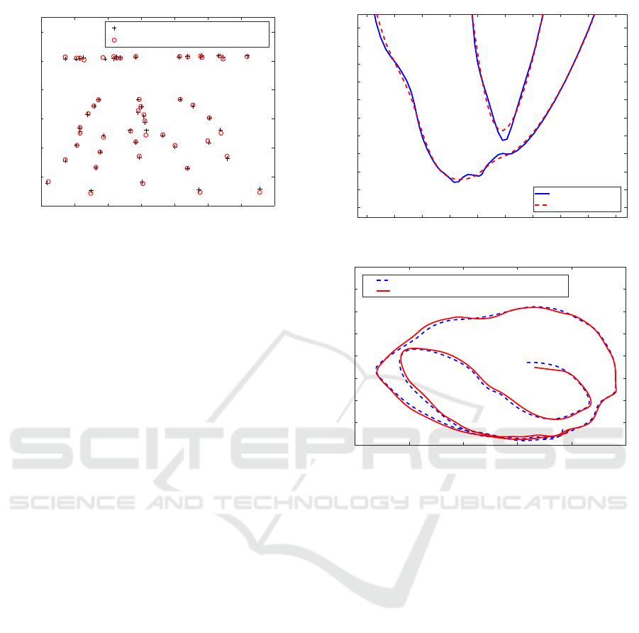
2D trajectory (true projection)
Estimated projection for 3D trajectory
Figure 4: Example of successful camera calibration and
temporal alignment.
As can be seen from Table 1, the method did not
work well with the filtered 3D data. A typical problem
was that the trajectory was estimated to be only a part
of the projection. Moreover, even in the cases were
the method worked for filtered data, the reprojection
error was smaller with the unfiltered data.
Using LOESS with the 10 percent span for filter-
ing the 2D trajectories resulted in slightly better re-
sults than with the 5 percent span. However, it should
be noted that when using a large span, the trajectories
already begin to loose their shape as can be seen from
Fig. 3. Therefore, a shorter span is recommended.
The method performed better when the selected two
random points were not allowed to be too close to
each other. When no such restraint was set, the whole
3D trajectory was often projected onto a single very
short line. The minimum of 6 points to estimate the
camera matrix was enough to achieve high success
rate. With a higher number of points, however, the
reprojection error was smaller. Fig. 4 shows a typical
successful camera calibration and temporal alignment
result.
Out of the two optimization criteria, Criterion 2
(mean distance) outperformed Criterion 1 (number
VISAPP 2017 - International Conference on Computer Vision Theory and Applications
448

Table 1: Results with filtered leap motion data and different combinations of method parameters (N is the number of points
used to estimate the camera matrix and D is the minimum distance between the two selected random points).
Method parameters Performance measures
Optimization Criterion LOESS span (%) N D Average distance Inliers (%) Success rate (%)
Criterion 1 5 6 1 - - 0.0
Criterion 1 5 10 1 - - 0.0
Criterion 1 10 6 1 - - 0.0
Criterion 1 10 10 1 17.77 92 3.4
Criterion 1 5 6 90 31.53 77 10.3
Criterion 1 5 10 90 23.24 77 31.0
Criterion 1 10 6 90 210.07 83 24.1
Criterion 1 10 10 90 20.99 79 48.3
Criterion 2 5 6 1 - - 0.0
Criterion 2 5 10 1 - - 0.0
Criterion 2 10 6 1 - - 0.0
Criterion 2 10 10 1 32.07 44 3.4
Criterion 2 5 6 90 47.09 54 62.1
Criterion 2 5 10 90 27.65 67 58.6
Criterion 2 10 6 90 36.77 70 65.5
Criterion 2 10 10 90 31.06 67 58.6
Table 2: Results with unfiltered Leap Motion data.
Method parameters Performance measures
Optimization Criterion LOESS span (%) N D Average distance Inliers (%) Success rate (%)
Criterion 1 5 6 1 - - 0.0
Criterion 1 5 10 1 - - 0.0
Criterion 1 10 6 1 - - 0.0
Criterion 1 10 10 1 17.20 94 3.4
Criterion 1 5 6 90 58.37 81 24.1
Criterion 1 5 10 90 23.80 74 72.4
Criterion 1 10 6 90 19.12 81 24.1
Criterion 1 10 10 90 19.51 79 72.4
Criterion 1 5 15 45 19.33 81 82.8
Criterion 1 5 15 90 21.50 79 82.8
Criterion 2 5 6 1 20.49 79 3.4
Criterion 2 5 10 1 18.65 86 10.3
Criterion 2 10 6 1 12.27 74 3.4
Criterion 2 10 10 1 21.79 72 13.8
Criterion 2 5 6 90 28.85 61 96.6
Criterion 2 5 10 90 23.11 69 93.1
Criterion 2 10 6 90 25.94 68 96.6
Criterion 2 10 10 90 21.54 71 96.6
Criterion 2 5 15 45 22.09 72 96.6
Criterion 2 5 15 90 21.50 73 96.6
of inliers). Criterion 1 failed to estimate the ma-
trix correctly in approximately one-third of the cases,
whereas Criterion 2 achieved over 96% success rate.
However, in those cases where Criterion 1 worked, it
outperformed Criterion 2 with respect to the accuracy.
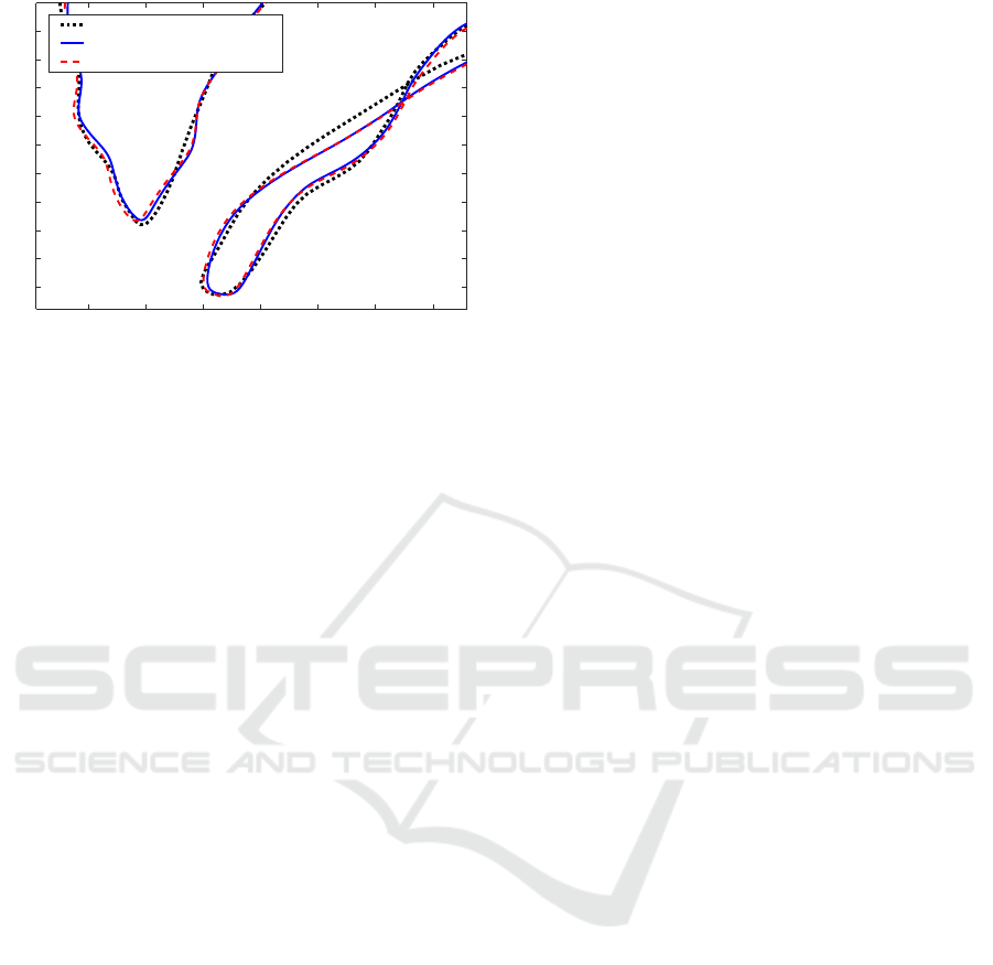
Fig. 5 shows a comparison of the two criteria with a
single trajectory.
5 CONCLUSION
We proposed a method to simultaneously calibrate
the camera and to temporally align 2D and 3D mo-
tion trajectories obtained by using a camera and Leap
Motion sensor. The experiments showed that by
properly tuning the method parameters, the approach
Simultaneous Camera Calibration and Temporal Alignment of 2D and 3D Trajectories
449
650 700 750 800 850 900 950
150
200
250
300
350
400
450
500
550
600
True projection
Estimate: RANSAC
Estimate: Mean Distance
Figure 5: Comparison of the optimization criteria.
achieved a high success rate with a test set consist-
ing of complex trajectories. The best results were ac-
quired by using unfiltered Leap Motion data, LOESS
smoothed 2D trajectory data obtained using the KCF
tracker, mean distance based optimization criterion,
10 points for the camera matrix estimation, and by re-
straining the minimum distance between the two ran-
dom points selected in each iteration. With the cur-
rent nonoptimized, single-core MATLAB implemen-
tation, the camera calibration and temporal alignment
takes about 30 minutes for trajectories of 10 seconds.
Future work will include enhancing the computation
performance in order to make the method efficient
for high-speed imaging. Besides combining the tra-
jectories recorded with a camera and 3D sensor, the
method provides an intuitive way to perform the cam-
era calibration and holds potential in other similar ap-
plications.
ACKNOWLEDGEMENTS
The research was carried out as part of the COPEX
project (No. 264429) funded by the Academy of Fin-
land.
REFERENCES
Abdel-Aziz, Y. (1971). Direct linear transformation from
comparator coordinates in close-range photogramme-
try. In ASP Symposium on Close-Range Photogram-
metry.
Caspi, Y. and Irani, M. (2000). A step towards sequence-
to-sequence alignment. In Proceedings of the IEEE
Conference on Computer Vision and Pattern Recogni-
tion, volume 2, pages 682–689.
Cleveland, W. S. (1979). Robust locally weighted regres-
sion and smoothing scatterplots. Journal of the Amer-
ican Statistical Association, 74(368):829–836.
El Akkad, N., Merras, M., Saaidi, A., and Satori, K. (2014).
Camera self-calibration with varying intrinsic param-
eters by an unknown three-dimensional scene. The
Visual Computer, 30(5):519–530.
Fischler, M. A. and Bolles, R. C. (1981). Random sample
consensus: a paradigm for model fitting with appli-
cations to image analysis and automated cartography.
Communications of the ACM, 24(6):381–395.
Heikkila, J. and Silv
´
en, O. (1997). A four-step camera
calibration procedure with implicit image correction.
In IEEE Conference on Computer Vision and Pattern
Recognition, pages 1106–1112.
Henriques, J. F., Caseiro, R., Martins, P., and Batista, J.
(2015). High-speed tracking with kernelized corre-
lation filters. IEEE Transactions on Pattern Analysis
and Machine Intelligence, 37(3):583–596.
Hiltunen, V., Eerola, T., Lensu, L., and Kalviainen,
H. (2014). Comparison of general object trackers
for hand tracking in high-speed videos. In 2014
22nd International Conference on Pattern Recogni-
tion (ICPR), pages 2215–2220. IEEE.
Knoop, S., Vacek, S., and Dillmann, R. (2009). Fusion of
2d and 3d sensor data for articulated body tracking.
Robotics and Autonomous Systems, 57(3):321–329.
Kuronen, T., Eerola, T., Lensu, L., Takatalo, J., H
¨
akkinen,
J., and K
¨
alvi
¨
ainen, H. (2015). High-speed hand track-
ing for studying human-computer interaction. In
Scandinavian Conference on Image Analysis, pages
130–141.
Liu, P., Shi, J., Zhou, J., and Jiang, L. (2003). Camera
self-calibration using the geometric structure in real
scenes. In Computer Graphics International, 2003.
Proceedings, pages 262–265.
Noguchi, M. and Kato, T. (2007). Geometric and timing
calibration for unsynchronized cameras using trajec-
tories of a moving marker. In IEEE Workshop on Ap-
plications of Computer Vision (WACV), pages 20–20.
IEEE.
Rahimi, A., Dunagan, B., and Darrell, T. (2004). Simulta-
neous calibration and tracking with a network of non-
overlapping sensors. In Proceedings of the IEEE Con-
ference on Computer Vision and Pattern Recognition
(CVPR), volume 1, pages I–187.
Rangarajan, K., Allen, W., and Shah, M. (1993). Matching
motion trajectories using scale-space. Pattern recog-
nition, 26(4):595–610.
Sturm, P. (2000). A case against kruppa’s equations for
camera self-calibration. Pattern Analysis and Machine
Intelligence, IEEE Transactions on, 22(10):1199–
1204.
Triggs, B. (1998). Autocalibration from planar scenes. In
European Conference on Computer Vision (ECCV),
pages 89–105.
Wu, Q., Shao, T.-C., and Chen, T. (2007). Robust self-
calibration from single image using ransac. In Third
International Symposium on Visual Computing, pages
230–237.
Zhao, Y. and Lv, X. (2012). An approach for camera self-
calibration using vanishing-line. Information Technol-
ogy Journal, 11(2):276–282.
VISAPP 2017 - International Conference on Computer Vision Theory and Applications
450
