
Deterministic Executable Models Verified Efficiently at Runtime
An Architecture for Robotic and Embedded Systems
Vladimir Estivill-Castro and Ren
´
e Hexel
School of ICT, Griffith University, Nathan Campus, 4111, Brisbane, Australia
Keywords:
Model-based Testing and Validation, Enactment and Execution, Reasoning about Models.
Abstract:
We show an architecture that enables runtime verification. Runtime verification focusses on the design of for-
mal languages for the specification of properties that must hold during runtime. In this paper, we take matters
one step further and describe a uniform modelling and development paradigm for software systems that can
monitor the quality of software systems as they execute, set-up, tear-down and enforce quality behaviour on
the fly. Our paradigm for modelling behaviour enables efficient execution, validation, simulation, and runtime-
verification. The models are executable and efficient because they are compiled (not interpreted). Moreover,
they can be developed using test-driven development, where tests are models derived from requirements. We
illustrate the approach with case studies from robotics and embedded systems.
1 INTRODUCTION
Software quality is critical to ensuring systems will
not cause harm or economic loss (Bryce and Kuhn,
2014). The Internet-of-Things (IoT) will demand
more reliable software systems (Kopetz, 2011). Gart-
ner estimates there are 736 million smart devices in
the IoT now across manufacturing, utilities, and trans-
portation. However, insufficient software quality can
cause the severe malfunction in smart embedded sys-
tems (Weiss et al., 2015; Sametinger et al., 2015; Sri-
vastava and Schumann, 2013).
The opportunities for improvements in software
quality are enormous: “risks are becoming salient as
our society comes to rely on autonomous or semi-
autonomous computer systems to make high-stakes
decisions” (Dietterich and Horvitz, 2015). The first
and immediate category to deal with are AI software
systems (Dietterich and Horvitz, 2015): automated
vehicles, home robots, and intelligent cloud services
must perform correctly, even in the presence of a sur-
prising or confusing input. Recommendations emerge
for researchers to focus on “self-monitoring architec-
tures in which a meta-level process continually ob-
serves the actions of the system, checks that its be-
haviour is consistent with the core intentions of the
designer, and intervenes or alerts if problems are
identified” (Dietterich and Horvitz, 2015).
Experts suggest that the software models for the
behaviour of the IoT and smart things are likely to be
based on state machines (Bryce and Kuhn, 2014), as
these make software development faster by specify-
ing the behaviour at a higher level of abstraction than
traditional programming languages. Use-case traces
naturally map to paths through states and transitions.
Behavior Engineering (Dromey and Powell, 2005), a
form of requirements engineering, creates these traces
and then integrates them into Behavior Trees, from
which finite-state machines, describing the behaviour
of components, can readily be synthesised.
We will show how to use logic-labelled finite-state
machines (LLFSMs) to model mechanisms that can
monitor the software system built from the model-
driven development (MDSD) paradigm that LLFSMs
offer. The precise semantics of LLFSMs makes them
overcome some of the criticisms that MDSD has re-
ceived (Picek and Strahonja, 2007) while enhancing
its advantages. LLFSMs have been proven very effec-
tive (Estivill-Castro et al., 2012) for describing soft-
ware behaviour and for performing model-checking
and formal verification, both in the value and the
time domain. LLFSMs offer a model of controlled
concurrency that scales much better than comparable
event-driven modelling approaches (such as UML-
state charts, Behavior Trees, and teleo-reactive sys-
tems). Consequently, changing, improving, and main-
taining behaviours of embedded systems and robots
using LLFSMs is more cost-effective. This high level
of modelling means that the behaviour is closer to
the original set of human-language requirements and
Estivill-Castro V. and Hexel R.
Deterministic Executable Models Verified Efficiently at Runtime - An Architecture for Robotic and Embedded Systems.
DOI: 10.5220/0006116700290040
In Proceedings of the 5th International Conference on Model-Driven Engineering and Software Development (MODELSWARD 2017), pages 29-40
ISBN: 978-989-758-210-3
Copyright
c
2017 by SCITEPRESS – Science and Technology Publications, Lda. All rights reserved
29

therefore easier to understand. In the systems en-
gineering and robotics communities, state-machines
are ubiquitous. MDSD leads to more uniform qual-
ity; the LLFSM compiler produces efficient executa-
bles as it compiles a general, uniform code that has
been structured to minimise overhead. Because of the
use of visual models of LLFSMs, the resulting be-
haviours are more transparent, and the gap between
business analysts, requirement engineers, and the de-
velopers is reduced. Moreover, to scale to larger
systems, LLFSMs have the capacity to incorporate
Test-Driven-Development (TDD) methods and derive
test suites from use-cases, incorporating such tests as
LLFSMs themselves (Estivill-Castro et al., 2015b).
Such TDD can be managed by Continuous Integra-
tion Servers (Estivill-Castro et al., 2015a).
Runtime verification focusses on the design of for-
mal languages for the specification of properties that
must hold during runtime (Drusinsky, 2005). In this
paper, we take matters one step further and will create
software systems that can monitor the quality of other
software systems as they execute, set-up, tear-down,
and enforce quality behaviour on the fly. We demon-
strate the progress with two concrete case studies: a
network of traffic lights and a robotic vehicle.
We use the fact that LLFSMs are executable mod-
els analogous to state charts, but with transitions la-
belled by logic. LLFSMs represent deterministic, ex-
ecutable models that enable formal specifications of
requirements, including observable behaviour. We
generate agents that can observe and monitor be-
haviour. This step enables deploying agent tech-
nology capable of identifying undesired behaviour,
consequentially raising warnings or acting to prevent
software malfunction. We use TDD and MDSD tools
for the automatic construction of runtime monitoring
agents that execute tests, monitor behaviour, and re-
vise software models as they execute. Our monitor-
ing LLFSMs raise the level by which the software is
aware of its operational state, since the monitoring
agents would be able to report on the behaviour of
their underlying software components.
The paper is organized as follows. Section 2 dis-
cusses the three architectural elements than enable our
approach. The first is the sequential scheduling of ar-
rangements of LLFSMs and that by labelling transi-
tions with Boolean expressions, and not event, they
are note event-driven. The second is the capability
to communicate between LLFSMs with a data cen-
tric in-memory middleware. The third element is the
use of control/status messages different from a pub-
lish/subscriber pattern and following a writers/readers
pattern. Section 3 discusses these architectural ele-
ments with a concrete example. This example will
be used in Section 4 to describe our approach to run-
time verification. While the first example (Estivill-
Castro and Hexel, 2014) is a simple embedded sys-
tem, Section 5 reviews what has been achieved with
robotic systems. Section 6 discusses how to automate
the process of generating monitoring LLFSMs while
Section 7 discusses the implications regarding safety
and security by contrasting with ROSRV (Huang et al.,
2014). Section 8 discusses the proposed work here
with the literature and Section 9 summarizes and con-
cludes the paper.
2 ARCHITECTURAL ELEMENTS
We base our architecture on executable models of be-
haviour represented by finite-state machines. Impor-
tantly, there are three crucial elements in this archi-
tecture.
First, transitions are labelled by Boolean ex-
pressions only (and not events), hence the name
logic-labelled finite-state machine (LLFSM). LLF-
SMs are Communicating Extended Finite State Ma-
chines (CEFSMs) without events (Li and Wong,
2002). Importantly, the semantics is therefore not that
of a software component waiting for an event trigger-
ing the switch to a new state. Instead, the components
form a single thread of LLFSMs under a predefined
schedule. The machine that executes (has the token)
evaluates the sequence of transitions associated with
its current state. This evaluation could potentially be
quite sophisticated and complex (involving planning
and/or reasoning), making LLFSMs, not plain reac-
tive architectures, but to also blend into deliberative
systems (Estivill-Castro et al., 2016; Estivill-Castro
and Ferrer-Mesters, 2013). Control remains with one
and only one component, resembling a deterministic
polling system (unlike an interrupt handler). If an ex-
pression labelling a transition evaluates to true, the
transition fires, making its target state the current state
of the LLFSM. As with ubiquitous models of state
machines, states have ONENTRY, and ONEXIT, and
INTERNAL sections. Actions (code) in the ONENTRY
section is executed only after a state change. The
ONEXIT section is executed after a transition fires,
while the INTERNAL section is executed only if all
transitions evaluate to false. After either, it becomes
the next machine’s turn in the arrangement. LLFSMs
have a series of mechanisms to handle composition,
and to be suspended, resumed or restarted. In addition
to interpreters for Simple C
1
and Java, we have ef-
ficient LLFSM compilers for C/C++ and Swift under
1
Simple C is a subset of C used in some examples of
antlr (Parr, 2013).
MODELSWARD 2017 - 5th International Conference on Model-Driven Engineering and Software Development
30

POSIX systems such as Linux or macOS, for micro-
controllers, and ROS. LLFSMs are akin to UML state
charts where transitions are labelled only by guards.
The second crucial element is the communica-
tion middleware between LLFSMs. A state in an
LLFSM, and even each section (ONENTRY, ONEXIT,
and INTERNAL), can have its own local variables,
not shared with any other scope; or they may have
the scope of the whole LLFSM. However, beyond
one LLFSM, variables reside in an object-oriented
whiteboard, implemented in shared memory (Estivill-
Castro et al., 2014). The whiteboard can be seen as a
data-oriented broker, decoupling readers and writers
of information. However, as opposed to most robotic
middlewares, where the paradigm of the consumer of
information is a Push approach, we use a Pull ap-
proach (Estivill-Castro and Hexel, 2015). With the
LLFSM execution semantics, our gusimplewhite-
board implementation (Estivill-Castro et al., 2014)
offers fast, lock-free, atomic reader/writer semantics
for multiple readers and even multiple writers. This
OO implementation has proven superior in speed and
reliability to other middlewares such as ROS’ sys-
tem (Joukoff et al., 2015; Estivill-Castro et al., 2014).
The third aspect that provides a simpler and
clearer semantics, while retaining modelling power
and Turing-complete expressivity, is data-centric
communication, between components utilising con-
trol and status messages. Thus, the whiteboard im-
plements a blackboard control architecture (Hayes-
Roth, 1988). Control/status messages are an al-
ternative to the scenarios akin to the rendezvous
model (Hoare, 1978; Pnueli et al., 1982) in the mes-
sage passing world, or a synchronous remote pro-
cedure call (RPC). By contrast, control/status mes-
sages follow the readers/writers paradigm as opposed
to producer/consumer or publisher/subscriber. Typi-
cally a single class definition is assigned two message
slots, Control for control data, and Status for re-
sponses (e.g., from a sensor). Both the actuator and
the controller components use the Pull paradigm to
query their corresponding message slots. This de-
coupling enables AI planning and reasoning agents
who can consume many CPU cycles to be incorpo-
rated without interfering with the control architecture
provided by LLFSMs (Estivill-Castro et al., 2016).
3 ILLUSTRATION OF
ARCHITECTURAL ELEMENTS
Consider now the LLFSMs in Figure 1. These ma-
chines are part of our later example for run-time ver-
ification and are the two behaviours of traffic lights
for a crossing of roads going East-West and North-
South. The first thing to notice is that analogous to
OMT (Rumbaugh et al., 1991) and UML, these ex-
ecutable models are made of states and transitions.
An arrangement of one of more LLFSMs constitutes
a single sequential program. That is, they are exe-
cuted in a single thread. The token of execution ro-
tates in round-robin fashion between the LLFSMs in
the arrangement. States have three sections, and when
the thread of execution arrives to an LLFSM the such
machine resumes execution. It verifies if it has not
been suspended, and whether it has executed a tran-
sition from another state the last time it was its turn.
If its execution derives from another of its states, the
ONENTRY section will be executed, otherwise it is
skipped. The turn of the machine consists of eval-
uating the guard of each transition leaving the cur-
rent state in sequence, and if one becomes true, then
execution of the ONEXIT completes the turn for this
LLFSM. If all transitions are false, the turn completes
by executing the INTERNAL section. Note that this
sequential semantics is due to the fact that labels for
the transitions are not events but Boolean expressions.
Machines are compiled into loadable libraries ensur-
ing efficiency over interpretation.
Boolean expressions like after(1) are analogous
to the predicates that were used in augmented finite-
state machines (AFSM) of the subsumption architec-
ture. In fact, the LISP language for the subsumption
architecture (Brooks, 1990) is a subset of LLFSMs.
Similarly, teleo-reactive programs (Nilsson, 2001) la-
bel all transitions with Boolean expressions. Consider
the code in the state RED ON NS. First the ONENTRY
section
SwitchSubsumptionTrafficLights aConfiguration =
wb handler.get();
aConfiguration.set theConfigurations(LIGHT NS RED,slot);
wb handler.set(aConfiguration);
shallGoGreenNS = red EW status t;
and also the INTERNAL section
shallGoGreenNS = red EW status t;
The statement in the INTERNAL section is also the
last statement of the ONENTRY section and illustrates
the use of a status message. The Boolean variable
shallGoGreenNS is updated by retrieving a status
message. The writer of this message is a compiled
Prolog program that evaluates whether the conditions
to move the North-South traffic light to green have
been meet (Estivill-Castro et al., 2016). Thus, if the
current state of this machine is RED ON NS, this ma-
chine will evaluate the variable shallGoGreenNS and
not carry out the transition while this variable has the
value false. But before relinquishing the token of
execution, it performs ints internal section where it
updates this transition labeling variable with the ad-
Deterministic Executable Models Verified Efficiently at Runtime - An Architecture for Robotic and Embedded Systems
31

(a) North-South (NS) controlling LLFSM. (b) East-West (EW) controlling LLFSM.
Figure 1: Two LLFSMs for traffic lights at a crossing.
vice from the Prolog program. This shows that the
models execute the reactive actions of moving to an-
other state in their own time, in an analogous fash-
ion to a time-triggered approach (and definitely dis-
tinctive from the event-driven approach of UML state
charts).
In our middleware, the data structures used to
communicate between LLFSMs (and other modules
like running Prolog programs in their own threads) are
essentially any C++ object with a standard C/C++ foot-
print in memory. This communication middleware is
illustrated also in this fragment of code. The state-
ment
SwitchSubsumptionTrafficLights
aConfiguration = wb handler.get();
uses a previously declared handler to the
middleware to retrieve the instance of
SwitchSubsumptionTrafficLights into the
object aConfiguration. The object-oriented nature
of this middleware follows a data centric white-
board paradigm, and thus, all methods to the class
SwitchSubsumptionTrafficLights are available.
This is what happens with
aConfiguration.set
theConfigurations(LIGHT NS RED,slot);
Here, the corresponding slot for this LLFSM is up-
dated in the data structure that the switch will use
to relay commands for the traffic lights. The next
statement posts this updated data structure back to the
whiteboard
wb handler.set(aConfiguration);
without any need for concurrency synchronisation as
the current LLFSMs in the arrangement knows no
other LLFSMs is accessing this object.
In summary, LLFSMs are models compiled into
loadable modules, not interpreted. They have been
compared to artefacts and modelling languages such
as Behavior Trees (Dromey and Powell, 2005), Event-
B (Abrial, 2010), Teleo-reactive programs (Nilsson,
2001), Executable UML (Mellor and Balcer, 2002),
or SysML (UML tailored for systems engineering).
For formal verification and requirements engineer-
ing, they compare favourably with Petri Nets (Billing-
ton et al., 2011) and Timed Automata (Estivill-Castro
et al., 2015b; Estivill-Castro et al., 2015a). Software
construction with LLFSMs can emulate architectures
based on embedded and reactive control as well as
behaviour-based control, while adding feasible, for-
mal verification (Estivill-Castro and Hexel, 2015). In
this paper, we take these elements further by enabling
an architecture for runtime verification.
4 ILLUSTRATIVE EXAMPLE
We present the principles of this new software archi-
tecture with a classical example (Maier and Warren,
1988) of a system that controls traffic lights on an in-
tersection between roads going North-South (NS) and
East-West (EW). Requirements evolve from an initial
version, with no sensors to a more advanced version
with sensors in the EW-direction that, in the absence
of a car, enable NS-priority (keeping the traffic lights
green in the NS-direction). The declarative require-
ments demonstrate the integration of reasoning and
logic-programming into a reactive system (Estivill-
Castro et al., 2016). The most crucial requirement,
of course, is that the lights are never simultaneously
green in both directions.
The complete system model consists of three
LLFSMs in a single arrangement:
2
the Timer LLFSM
and two controller LLFSMs. Each controller LLFSM
is in charge of a traffic direction and thus, minimally,
each is in charge of a set of three lights (a read, a
green and an amber light). Two versions of a declara-
tive Prolog program (https://youtu.be/HFm6fbZ6lkg)
specify when to switch lights. The Timer machine can
be signalled to reset the time value, it regularly posts
the time elapsed, and whether that time is greater than
2
A GUI facade with avatars for effector and sensor
hardware appears in the simulation at https://youtu.be/
HFm6fbZ6lkg.
MODELSWARD 2017 - 5th International Conference on Model-Driven Engineering and Software Development
32
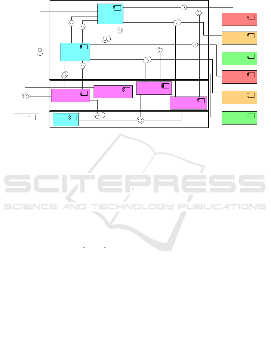
Layer 3
Layer 2
Layer 1
ShallGoGreenNS
RedEWon
ShallGoRedNS
AmberNSon
ShallWarnNS
GreenNSon
RedEWon
TimerReset
ShallGoGreenEW
ShallGoRedEW
TimerReset
AmberEWon
ShallWarnEW
GreenEWon
«wrapper»
shallMoveNStoRed (llfsm)
timeGT30
timeGT5
detectEW
«wrapper»
shallMoveNStoAmber (llfsm)
«wrapper»
shallMoveEWtoRed (llfsm)
NS control (llfsm)
Red Light NS (effector)
Red Light EW (effector)
Amber Light NS (effector)
Amber Light EW (effector)
Green Light EW (effector)
Car sensor
Green Light NS (effector)
EW control (llfsm)
«wrapper»
shallMoveEWtoAmber (llfsm)
Timer (llfsm)
Figure 2: Layered component diagram of the LLFSMs executable software that control the traffic lights.
5 seconds, or greater than 30 seconds.
3
The LLFSM
for the EW-set of lights controls the green, amber and
red light in the EW-direction, cycling through three
states such that only one light is on in each state.
4
Thus, in the state On RED EW, in the EW-direction,
only the red light is on. Symmetrically, the sec-
ond controller LLFSM handles the NS-direction, sig-
nalling red, amber, and green in that direction, also
cycling from green via amber to red, and back to
green. All three LLFSMs are scheduled determinis-
tically, and the decisions as to whether to switch state
are inspections of Boolean variables on the white-
board. For example, shallGoRedNS is evaluated by
obtaining the value from the whiteboard with the
statement shallGoRedNS=stopNS status t; that is,
the LLFSM acts as a reader in the Pull architecture of
this status message, while the value is updated by a
writer that periodically executes the Prolog program.
The Prolog program is inside a wrapper LLFSM run-
ning in another thread. Such wrapper is synthesised
from the Prolog program. Details of the Pull vs Push
approach and the control/status approach to constrain-
ing concurrency to the readers/writers model (vs. pub-
lisher/subscribers) appear elsewhere (Estivill-Castro
and Hexel, 2013; Estivill-Castro et al., 2016). Our fo-
cus here is that the system is complete and functional
and constitutes an executable model.
Using the sensor and prioritising the NS-direction
3
Diagram for the Timer is 40s into the video (https://
youtu.be/HFm6fbZ6lkg).
4
The EW-controller diagram is displayed and explained
from 1m 18s.
is the result of a simple, localised change, restricted
to only the Prolog program. Changing between soft-
ware versions requires swapping between Prolog pro-
grams. The LLFSMs can be subject to formal ver-
ification (using standard model-checking tools), as
the corresponding Kripke structure can be derived
directly from the model (and the number of Kripke
states is small). In addition, since sometimes express-
ing properties about system behaviour to perform for-
mal verification can be difficult, it is possible to cre-
ate a suite of TDD tests by creating test-LLFSMs
that set-up, watch, and tear-down the operation of the
system (Estivill-Castro et al., 2015a; Estivill-Castro
et al., 2015b). Such testing can validate the system be-
fore investing effort into formal verification, and also
can raise the confidence of system correctness where
state explosion makes formal verification impossible.
We focus on the situation where replacing one
behaviour component or any of the four wrappers,
at runtime, could result in a faulty system. That is,
one should be able to swap between versions without
faults manifesting themselves. Of course, one way is
to formulate these details as a requirement and build
the software accordingly. However, if the decision-
making process is learnt while running (the Prolog
program is composed by something akin to inductive
logic programming), then no possible test could have
been created originally, as the logic program would
not have existed at the time. Once the logic program is
available, formal verification may be infeasible (due
to the complexity of the system), while testing does
not prove the system is correct: it merely shows that
no failures occur in a finite subset of cases. More-
Deterministic Executable Models Verified Efficiently at Runtime - An Architecture for Robotic and Embedded Systems
33

over, if big data technologies and stream-data analyt-
ics were to build, online, sophisticated new rules and
software to decide on the settings of the traffic lights,
exhaustive testing would be infeasible. Thus, moni-
toring the system while in execution may actually be
required, to correct the effects of traces that lead to
failure, but were not discovered earlier.
We propose a revolution of the subsumption archi-
tecture (Brooks, 1986) to manage the runtime verifi-
cation of a system composed of LLFSMs. Our pro-
posal, following the subsumption architecture princi-
ples, constructs behaviour from conceptual layers of
timed, finite-state machines. What we suggest here is
a revolution, because we no longer assume lower lay-
ers are correct. The timed aspect means that we have
Boolean primitives, after(t), that only become true
after t units of time. We, however, go beyond a mech-
anism to just suppress an input, and even beyond the
capacity to inhibit the output from an LLFSM. In-
stead, we extend the mechanism to suspend (Estivill-
Castro et al., 2014) an LLFSM and add a mechanism
that dynamically loads an LLFSM to join and exe-
cute in the arrangement. Correspondingly, we pro-
vide mechanisms to also dynamically unload a faulty
LLFSM and remove it from the schedule of execution.
The subsumption architecture builds levels of pro-
gressively more sophistication, always assuming that
the lower layers were entirely correct. In stark con-
trast, we propose that the lower layers may, in fact,
be faulty. In our proposal, higher levels act as be-
haviour monitors for lower layers. Realisation by a
higher layer that a lower layer is malfunctioning, per-
haps violating some requirement, is sufficient for the
higher layer to take action, including one or several of
the following actions.
1. Inhibit the output of the lower layers and replacing
it with newer, safer output.
2. Provide input to lower-level machines to steer
them, suspend them and/or restart them.
3. Reconfigure the arrangement by unloading some
of its LLFSMs and loading non-faulty replace-
ments.
That is, higher layers can rebuild lower layers that
exhibit unstable behaviour. Figure 2 shows a com-
ponent diagram (with the inputs and outputs for the
traffic lights and sensor) in the layered style of the
subsumption architecture (Brooks, 1986). Our ap-
proach is to take such a system (that receives input
from sensors drawn on the left and delivers outputs
to actuators) to an expanded and safer level, where
a monitor (with a subsumption switch) ensures fun-
damental safety properties during runtime. This is
illustrated by the transformation in Figure 3, where
3(a) follows (Brooks, 1986, Page 17, Fig. 3) to Fig-
ure 3(b). Note that the original system can be ab-
stracted and treated as a black box from the perspec-
tive of the two new components. The first component
is a monitor LLFSM, while the second one is a sub-
sumption switch (C
ˆ
ot
´
e et al., 2006) that can also be
modelled/implemented as a (separate) logic-labelled
finite-state machine. The added modules can treat the
entire set of output signals of the system as inputs
(“external” signals from their perspective). The added
components (coloured boxes in Figure 3(b)) are small
and thus their formal verification becomes feasible.
More importantly, the switch LLFSM is capable of
inhibiting dangerous configuration of output signals
to the actuators, replacing them with safer configura-
tions. The monitor LLFSM can perform all the ac-
tions suggested earlier that reconfigure the running
system.
Our extension creates a more uniform layered ar-
chitecture, whether or not the original system is a sub-
sumption architecture. The LLFSM for the switch
5
simply buffers configurations of effector and actuator
commands with a given priority.
If the system is a subsumption architecture, the
switches already are part of the system and do not
need to be replicated. The only requirement is that
configurations provided by the monitors have a higher
priority level. Moreover, the monitoring LLFSM can
have its own API, as we will discuss later.
The generality of the LLFSM approach facilitates
that the monitor be also a monitoring LLFSM, and
therefore, the monitor is in itself another executable
model
6
. For the traffic light system, the monitoring
LLFSM checks that the two green lights are never on
simultaneously. The monitor will inhibit this via a
signal to the switch, which will trigger blinking am-
ber lights in both directions (with all red and green
lights turned off). This behaviour signals malfunction
to motorists and to the traffic authorities. When the
monitor discovers a fault, it loads a machine that ex-
presses a new behaviour (both lights blinking amber),
and unloads the current faulty machine, loading de-
fault ones. This construction is the generic machine-
monitoring pattern.
5 ROBOTICS CASE STUDY
Our second case study is inspired by the presentation
of the runtime verification framework ROSRV (Huang
et al., 2014). This framework aims at raising the
5
https://youtu.be/HFm6fbZ6lkg at 3m 32s.
6
From 3m 40s in the above video.
MODELSWARD 2017 - 5th International Conference on Model-Driven Engineering and Software Development
34
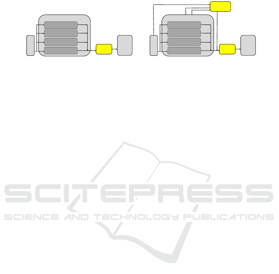
SENSORS
ACTUATORS
SYSTEM
LAYER&1
LAYER&2
LAYER&3
LAYER&4
SWITCH
(a) Illustration of the layered subsumption archi-
tecture.
SENSORS
ACTUATORS
SYSTEM
LAYER&1
LAYER&2
LAYER&3
LAYER&4
MONITOR
SWITCH
(b) With a monitor LLFSM and potentially an-
other switch properties of the system can be mon-
itored and actions taken at run time.
Figure 3: Generic architecture of the safety monitor.
level of safety in robotic systems under ROS and
mainly consists of a node named RVMaster. It over-
sees all the peer-to-peer traffic in a ROS environment,
blocking messages, and shielding the actual Master
node (usually named roscore). The ROSRV architec-
ture places a Monitor between every pair of publish-
ers/subscribers, requiring a large number of monitors.
The link between the RVMaster and the ROS Master
is secured with a firewall.
This framework is illustrated using a simulator
of the LandShark unmanned ground vehicle (UGV)
robot. The examples represent situations where two
modules responsible for two different tasks (although
optimised for their individual responsibilities), when
operating simultaneously, produce an overall deficient
behaviour. One such example is a gun on the tur-
ret having a tracker for a target but when placed on
the LandShark UGV body it may hit itself (Huang
et al., 2014). These scenarios are common in other
robotic software, and another example discussed with
the UGV simulator is combinations of turret positions
and accelerations causing it to tip over (Huang et al.,
2014). Although there is no public access to the Land-
Shark simulator, we can reproduce two of the moni-
toring examples using the ROS Gazebo simulation of
a Komodo, a robot that is also an UGV on wheels with
an articulated arm and gripper. The forbidden runtime
conditions we monitor are actuator commands rather
than conditions about forbidden states.
The first scenario is that certain wheel accelera-
tions are not to be set while the arm is extended, as
this causes the robot to tip. Second, certain naviga-
tion commands are not to be performed as they would
take the robot into unsafe terrain. For this last exam-
ple we have a video (https://youtu.be/MVlghB0JZ1g)
that shows one behaviour for exploring a region that
is faulty, becoming more prone to accelerate and run
into barriers. However, with our runtime verification
monitor, when the robot is close to the obstacles, two
new behaviours are loaded, one to spin it back and one
to guide it to its origin before the earlier behaviour is
allowed to operate again. The methodology presented
before applies here in a very similar way. We add a
subsumption switch to the original system that wraps
the motor commands. We add monitoring LLFSMs
for the conditions. One simply uses location informa-
tion directly to track the position of the robot and thus
instructing the switch to inhibit motion commands to
motors that would place the robot too close to the ob-
stacles. For the other example, the monitor LLFSM
reads the arm position sensors, to calculate and track
the centre of gravity relative to the base of the robot,
adjusting a threshold value in the subsumption switch
for the maximum allowed wheel acceleration.
6 AUTOMATIC GENERATION
In principle, any runtime verification formalism (Alur
and Henzinger, 1992; Thati and Ros¸u, 2005) could
be embedded in a monitoring LLFSM because LLF-
SMs are Turing complete. However, we have cho-
sen a simple mechanism that seems to fit most cases
and, moreover, enables the construction of the mon-
itoring LLFSMs from the visualisation of the system
LLFSMs. The idea is to evolve LLFSMs constructed
for TDD (Estivill-Castro et al., 2015a; Estivill-Castro
et al., 2015b) into monitors.
We explain our aproach using the earlier exam-
ple. The monitored conditions are rather simple. The
LLFSM for TDD verifies that the controller LLFSMs
are not in designated states simultaneously (e.g., turn-
ing all lights to green). This can also be achieved
by monitoring the outputs of writer LLFSMs on the
whiteboard. In the traffic light example, this would
be the message to actuator lights for both green lights
to be on.
Therefore, we suggest here that we can have a
rather strong logic to express conditions to monitor
the runtime validity of LLFSMs that are in the Sys-
tem box of Figure 3. Moreover, the monitor LLFSM
in Figure 3 would be a model constructed completely
Deterministic Executable Models Verified Efficiently at Runtime - An Architecture for Robotic and Embedded Systems
35

from these logic expressions, significantly automat-
ing the implementation of such monitoring LLFSMs.
First, we can describe the basic constructs of the logic
to express forbidden conditions by monitoring LLF-
SMs. The first building blocks are formulas.
<formula> → <term> | (<formula> <connective>
<formula>) | not(<formula>)
<term> → <state formula> | <wb variable formula>
<state formula> → <machine name> @ <state name>
<wb variable formula> → <value> == <wb variable name>
<connective> → ∧ | ∨
An example of the term that expresses that in the
LLFSM arrangement of the traffic lights the two con-
trolling machines cannot both be in their respective
states where they set their respective lights to green is
the following formula.
light ns subsumption @ GREEN ON NS
∧
light ns subsumption @ GREEN ON EW
Similar formulas can be constructed for many
of the safety requirements of the systems discussed
in the literature of formal verification and software
safety. For example, in the case of a microwave, a
crucial requirement is the motor/radiation is not to be
on while the door is open:
true == doorOpen ∧ true == motorOn
The microwave is a widely discussed example in the
literature of formal verification and model check-
ing (Asarin et al., 2002). We point out here that
from forbidden-condition formulas, the automatic
construction of the LLFSM that monitors whether the
formula evaluates to true (realises the forbidden con-
dition) is rather simple. It consists of a simple loop
where the information for the formula is retrieved
from the whiteboard and then the formula is evalu-
ated. Thus, our LLFSM generator only requires a
parameter that indicates the period of the loop (us-
ing the after() construction mentioned before) and
what LLFSM to activate in case the forbidden formula
is realised. The designer of our runtime verification
LLFSMs uses a GUI to choose states from LLFSMs
to build hstate formulai and also to select white-
board variables to build these formulas from. When
whiteboard variables refer to objects, the GUI pro-
vides a drop-down menu to select getters to obtain
an expression that evaluates to a basic type.
It should be clear that our logic for forbidden for-
mulas is structurally and semantically equivalent to
propositional logic. As we already mentioned, an
LLFSM that checks such a formula is built by basi-
cally including the forbidden formula in a transition
from a state that has read the necessary information.
Such monitoring LLFSMs, although synthesised au-
tomatically are quite impenetrable to human design-
ers. Most of the conditions or rules we have found
in case studies on system safety seem to be of this
form. However, we have noted that in some situa-
tions the forbidden scenario more closely corresponds
to a trace of a behaviour. That is, the undesirable be-
haviour is not that, at a certain point in time, a cer-
tain configuration of variable values or states of sub-
LLFSMs is reached in a system.
More elaborate, forbidden situations are se-
quences of formulas. For example, with the traf-
fic lights, control in each direction cycles between
green, amber, and red (then back to green). In
this case, the forbidden behaviour can be speci-
fied by the complement of the regular expression
(green amber red)
?
. Moreover, the equivalence of
regular expressions and non-deterministic automata
(and thus, deterministic automata) shows that we can
construct monitoring LLFSMs automatically that ver-
ify that the system does not have a trace of basic for-
mulas (about states and whiteboard variables) that be-
longs to a regular language where the alphabet are ba-
sic formulas. These monitoring LLFSMs are not ex-
pected to be drawn or presented for inspection by hu-
man designers, they can be rather large (even if we ap-
ply classical algorithms for DFA minimisation in the
building of the corresponding monitoring LLFSM).
However, the corresponding regular expressions are
quite manageable by system designers. Today, for ex-
ample, many programming languages or (web) search
facilities, offer tools to construct and visualise regu-
lar expressions. Thus for now, we consider this as-
pect less of a priority except that the architecture pro-
posed here integrates the resulting monitoring LLF-
SMs quite naturally for expressing a language of for-
bidden traces in the running system under verification.
Our clfsm tool enables the introspection of the run-
ning system to obtain the trace of the system’s state
changes. This is another aspect in which the deter-
ministic scheduling of arrangements of LLFSMs is an
advantage, as the traces are not subject to pre-emptive
scheduling if, for example, each LLFSM were to run
as a separate thread.
The spot package allows the derivation of moni-
tors (option -M for ltl2tgba); and we could use the
spot libraries to automatically synthesise the moni-
tor for our architecture directly as an LLFSM. In sev-
eral robotic systems with planning and manipulation
tasks, the LTL subset named co-safe LTL has been
used (He et al., 2015) because it produces determin-
istic finite-automata (Kupferman and Vardi, 2001).
Here again, B
¨
uchi automata can be directly modelled
by LLFSMs. Our architecture can confirm co-safe
LTL formulae, but if the formula has the modal op-
erator for “eventually”, the monitoring LLFSM can
not guarantee when such a condition is met (in the
MODELSWARD 2017 - 5th International Conference on Model-Driven Engineering and Software Development
36

case of task planning it enables one to recognise a
plan has found a goal meeting the co-safe LTL con-
dition). However, we are studying a possible form
of these logics or their variations for future bounded
temporal logics. Note that timed regular expressions
are equivalent to timed automata (Asarin et al., 2002).
However, timed automata are non-deterministic in the
sense that their execution/simulation on a computer is
only one of the many execution paths. Thus, at the
moment, these other formalisms to specify undesir-
able behaviours seem to demand a monitoring instru-
ment that would be resource intensive.
7 SAFETY AND SECURITY
ISSUES
Our architecture provides compile-time type safety
because commands between LLFSMs and from the
subsumption switch to effectors and actuators are
OO-messages on the gusimplewhiteboard. The
only LLFSM that has access to these message types
is the subsumption switch. All other LLFSMs only
have access to the abstraction and interface the sub-
sumption switch offers. Other LLFSMs cannot ac-
cess effectors and actuators directly. The subsump-
tion switch only forwards specific commands (to ef-
fectors and actuators) if such commands are placed
in corresponding slots of the hierarchy by the re-
spective LLFSMs of the system or the monitor. Our
compile-time type safety is significantly more se-
cure than RVMaster (Huang et al., 2014) because,
for RVMaster, the underlying middleware is in itself
ROS, lacking any security mechanisms (Huang et al.,
2014): ROS allows any node to read all the available
topics and services at runtime.
In our proposal, we restrict which LLFSMs in an
arrangement can perform operations such as load, un-
load, suspend, and resume. But monitoring LLFSMs
have clearance for such operations on system LLF-
SMs. We are assuming that the software would need
to exist in an environment isolated from penetration of
malicious users who could plant such malicious LLF-
SMs in the paths read by the clfsm instance executing
the arrangement. The runtime verification here aims
at safety by protecting from Byzantine faults of well-
intentioned components that have evolved though po-
tentially independent constraints and objectives, and
whose synergies could cause malfunction in the sys-
tem.
Evolving software modules (for learning a walk
on a quadruped robot, or for tracking with a neck
or turret with additional degrees of freedom), opti-
mise their main task and thus they have a restricted
range of messages for certain restricted families of ef-
fectors/actuators. We assume that system security is
such that validated LLFSMs cannot be replaced with
malicious ones. Moreover, the monitoring LLFSM is
able to reset self-modifying modules by unloading the
learnt/evolved, detrimental behaviour causing poor
synergies with other modules and load a validated be-
haviour. In our traffic lights example, the video il-
lustrates rebuilding at execution time the default be-
haviour and unloading the initial faulty behaviour.
Another example is a robot learning to control its
arm as it discovers the environment (see our video
https://www.youtube.com/watch?v= 3VylSPQoEE).
The whiteboard middleware discussed earlier pro-
vides a channel to monitoring LLFSMs (monitors).
Thus, monitors could receive the suspend command.
This enables testing systems without the monitoring
(which could be resumed later) or running the system
under different configurations of the properties that
are being monitored. This facility to also configure
monitoring systems during runtime has been used be-
fore (Huang et al., 2014), and in our proposal here
is immediately available through the existing mecha-
nisms of the whiteboard. Thus, it is possible to ex-
tend the subsumption architecture and the hierarchy
of clearance classes by more than one level. Monitor-
ing LLFSMs are also controllable. The suggested ear-
lier transformation (from Figure 3(a) to Figure 3(b))
of adding a subsumption switch and a monitor (both
LLFSMs) can be re-iterated several times as design-
ers see fit, with higher levels being able to suspend,
decommission, reload, and/ or reconfigure the com-
ponents of the lower layers underneath.
8 CONTRAST WITH RELATED
WORK
Runtime Verification (Kim et al., 1999; Havelund,
2000) focusses on how to monitor, analyse, and
guide the execution of software, using lightweight
formal methods applied during the execution of pro-
grams. Although formal validation of properties
against running systems has been a long-standing
concern in software engineering (for example in-
stance dynamic typing), our suggestion here follows
the current practices in testing (particularly model-
based testing) when used before and during deploy-
ment of fault-tolerant systems. Note that the cur-
rent practice for detecting and possibly reacting to
observed behaviours satisfying or violating certain
properties is to represent such properties with trace-
predicate formalisms, such as finite state machines,
regular expressions, context-free patterns, and lin-
Deterministic Executable Models Verified Efficiently at Runtime - An Architecture for Robotic and Embedded Systems
37

ear temporal logics. LLFSMs are extremely suitable
to describe verification properties and encompass all
of the earlier mechanisms, as they are Turing com-
plete (Estivill-Castro and Hexel, 2013).
Note that a large number of tools and approaches
have been produced for the runtime monitoring of se-
quential or concurrent programs in traditional coding
languages such as C++, C, and Java (Delgado et al.,
2004); however, essentially no work has appeared for
carrying out runtime verification using model-driven
development tools. The reliability of time-triggered
systems is significantly easier to determine than that
of event-triggered systems (Kopetz, 1993; Lamport,
1984). Time-triggered systems handle peak-load situ-
ations by design, enable software components to com-
municate using constant bandwidth and regular over-
head even at peak load situations. By contrast, event-
driven systems are inherently unpredictable, they can
collapse during peak loads or event showers, and no
analytical guarantees can be given for their perfor-
mance (Kopetz, 1993; Lamport, 1984). Surprisingly
runtime-verification tools have been proposed using a
modeling approach based on events (Barringer et al.,
2012; Colombo et al., 2008) and that their implemen-
tation is made in Java with unrealistic claims regard-
ing real-time verification (but an admission of this is-
sue is present (Colombo et al., 2008, Page 141)).
Such monitor-oriented programming (Chen and
Ros¸u, 2003), in the environment of robotics systems,
(in particular the Robotics Operating System ROS)
requires ROSRV as an arbiter (Huang et al., 2014)
of the appropriateness of message passing, introduc-
ing additional message relays and potential critical
delays. Nevertheless, as discussed in the presenta-
tion, ROSRV is perhaps the closest approach related
to our proposal here; but our architecture compares
favourably. In ROSRV, security, scalability, and for-
mal verification were identified as issues for further
work (Huang et al., 2014). With respect to security,
ROSRV solely relies on network routing of trusted IP
addresses. Moreover, ROSRV is centralised and poli-
cies and monitors need to be established for each pub-
lisher/subscriber pair, which does not scale well. The
LLFSMs that act as the switch and the monitor can
be formally verified in our architecture. We have also
identified other advantages of our proposal, namely
the specification of conditions to monitor are naturally
and automatically derived and expressed from the
LLFSM models in model-driven development style.
We would argue that the subsumption architec-
ture (Brooks, 1986) and teleo-reactive systems are
now classical mechanisms to produce reactive sys-
tems, that, in their inception, have been logic-labelled
(and not event-driven), and in the case of the for-
mer, been significantly revolutionising the software
architectures of robotic systems towards behaviour-
based systems. In the case of the latter, several ad-
vances have been made to enable them with formal
verification tools (Dongol et al., 2014) or implemen-
tation tools (S
´
anchez et al., 2012). However, teleo-
reactive programs do have the danger of undefined
behaviour (Hayes, 2008).
Both, the subsumption architecture and teleo-
reactive systems, suffer issues with their semantics of
concurrency analogous to the issues of nested state-
diagrams in UML. Issues such as state nesting (Si-
mons, 2000) or other ambiguities (von der Beeck,
1994; Simons, 2000), have resulted in several prob-
lems with executable UML and its use in Model-
Driven-Development. Most tools and approaches on
formal methods based on UML must restrict them-
selves: for example, restrictions to the consistency
and completeness of the artefact (Pap et al., 2005)
or to Practical Formal Specification’s (PFS) where
events are precluded and component communications
happen only through their declared inputs and out-
puts (Iwu et al., 2007). The community seems to
largely follow Harel and Gery’s executable model of
hierarchical statecharts (Harel and Gery, 1996), which
has an execution semantics akin to a remote proce-
dure call (RPC) under the Run-to-Completion Execu-
tion Model (RTC) (Samek, 2008, Page 2.2.8): that is,
the system keeps queueing events, while handling an
earlier event. Such complicated semantics and run-
time uncontrolled concurrency results in much higher
complexity of runtime verification.
9 REFLECTION AND
CONCLUSION
Clearly, software should be validated and verified be-
fore being deployed into production, and the present
work here in runtime verification does not intend
to minimise the critical role of validation, verifica-
tion, and testing. However, as we move into soft-
ware that adapts and evolves while in execution, it
becomes much more critical to additionally ensure
correctness at runtime. As the capabilities of artifi-
cial intelligence, such as machine learning, matures,
large systems will increasingly update their parame-
ters, threshold values, or entire components during
their life time. One alternative to runtime verifica-
tion is that the trace of a running system be potentially
logged as data sets for machine learning, from which
to create a verified and validated system to replace the
system in operation. Such an approach may be worth-
while; however, it would miss the ability of incor-
MODELSWARD 2017 - 5th International Conference on Model-Driven Engineering and Software Development
38

porating experiences learnt between validated snap-
shots. Instead, one would like to have a running sys-
tem that is always learning and using the best infer-
ences from its continuous operation.
Moreover, we have demonstrated that we can even
decommission LLFSMs in the arrangement and let
the temporary inconsistent behaviour be managed by
the supervising behaviour. Such a replacement of one
or more LLFSMs in a system could be significantly
more organic, depending on particular external fac-
tors that have caused the system to evolve in particular
ways, which cannot be entirely anticipated and veri-
fied. Thus, the need for runtime verification. The soft-
ware may very well outlive its designers and develop-
ers as it continues to operate uninterruptedly. In fact,
a key point of software quality is minimal downtime
and continuous operation. Such is our expectation al-
ready of, for example, the web, where there is a large
number of components (servers) that are down, while
the system as a whole continues to operate and renew
itself without global down-time. Here, we transfer
this into the world of robotics and complex, safety-
critical real-time systems. Software re-use should im-
ply that elements and components continue to execute
despite others being down.
REFERENCES
Abrial, J.-R. (2010). Modeling in Event-B — System and
Software Engineering. Cambridge University Press.
Alur, R. and Henzinger, T. A. (1992). Logics and models
of real time: A survey. Real-Time: Theory in Prac-
tice, REX Workshop, p. 74–106, London, UK, UK.
Springer-Verlag.
Asarin, E., Caspi, P., and Maler, O. (2002). Timed regular
expressions. J. ACM, 49(2):172–206.
Barringer, H., Falcone, Y., Havelund, K., Reger, G., and Ry-
deheard, D. E. (2012). Quantified event automata: To-
wards expressive and efficient runtime monitors. 18th
Int. Sym. FM 2012: Formal Methods, p. 68–84.
Billington, D., Estivill-Castro, V., Hexel, R., and Rock, A.
(2011). Requirements engineering via non-monotonic
logics and state diagrams. Evaluation of Novel Ap-
proaches to Software Engineering, v. 230, p. 121–135,
Berlin. Springer.
Brooks, R. (1986). A robust layered control system for a
mobile robot. Robotics and Automation, IEEE Journal
of, 2(1):14–23.
Brooks, R. (1990). The behavior language; user’s guide.
Tech. Report AIM-1227, Massachusetts Institute of
Technology, Artificial Intelligence Lab Publications,
Department of Electronics and Computer Science.
Bryce, R. and Kuhn, R. (2014). Software testing [guest
editors’ introduction]. Computer, 47(2):21–22.
Chen, F. and Ros¸u, G. (2003). Towards monitoring-oriented
programming: A paradigm combining specification
and implementation. Electr. Notes Theor. Comput.
Sci., 89(2):108–127.
Colombo, C., Pace, G. J., and Schneider, G. (2008). Dy-
namic event-based runtime monitoring of real-time
and contextual properties. Formal Methods for In-
dustrial Critical Systems, 13th Int. Workshop, FMICS
2008, p. 135–149.
C
ˆ
ot
´
e, C., Brosseau, Y., L
´
etourneau, D., Ra
¨
ıevsky, C., and
Michaud, F. (2006). Robotic software integration us-
ing MARIE. Int. Journal of Advanced Robotic Sys-
tems, 3(1):055–060.
Delgado, N., Gates, A. Q., and Roach, S. (2004). A taxon-
omy and catalog of runtime software-fault monitoring
tools. IEEE Trans. Softw. Eng., 30(12):859–872.
Dietterich, T. G. and Horvitz, E. J. (2015). Rise of concerns
about ai: Reflections and directions. Commun. ACM,
58(10):38–40.
Dongol, B., Hayes, I. H., and Robinson, P. J. (2014). Rea-
soning about goal-directed real-time teleo-reactive
programs. Formal Asp. Comput., 26(3):563–589.
Dromey, R. G. and Powell, D. (2005). Early requirements
defect detection. TickIT Journal, 4Q05:3–13.
Drusinsky, D. (2005). Semantics and runtime monitoring
of tlcharts: Statechart automata with temporal logic
conditioned transitions. Electr. Notes Theor. Comput.
Sci., 113:3–21.
Estivill-Castro, V. and Ferrer-Mesters, J. (2013). Path-
finding in dynamic environments with PDDL-
planners. 16th Int. Conf. on Advanced Robotics
(ICAR), p. 1–7, Montevideo, Uruguay.
Estivill-Castro, V. and Hexel, R. (2013). Arrangements
of finite-state machines semantics, simulation, and
model checking. Int. Conf. on Model-Driven Engi-
neering and Software Development MODELSWARD,
p. 182–189, Barcelona, Spain. SCITEPRESS Science
and Technology Publications.
Estivill-Castro, V. and Hexel, R. (2014). Run-time veri-
fication of regularly expressed behavioral properties
in robotic systems with logic-labeled finite state ma-
chines. 2016 IEEE Int. Conf. on Simulation, Model-
ing, and Programming for Autonomous Robots, SIM-
PAR, San Francisco, CA. to appear.
Estivill-Castro, V. and Hexel, R. (2015). Simple, not
simplistic — the middleware of behaviour models.
ENASE 10 Int. Conf. on Evaluation of Novel Ap-
proaches to Software Engineering, Barcelona, Spain.
INSTCC.
Estivill-Castro, V., Hexel, R., and Lusty, C. (2014). High
performance relaying of C++11 objects across pro-
cesses and logic-labeled finite-state machines. Sim-
ulation, Modeling, and Programming for Autonomous
Robots - 4th Int. Conf., SIMPAR 2014, v. 8810 LNCS,
p. 182–194, Bergamo, Italy. Springer.
Estivill-Castro, V., Hexel, R., and Ram
´
ırez Regalado, A.
(2016). Architecture for logic programing with ar-
rangements of finite-state machines. Cheng, A. M. K.,
editor, First Workshop on Declarative Cyber-Physical
Systems (DCPS) at Cyber-Physical Systems, p. 1–8.
IEEE.
Estivill-Castro, V., Hexel, R., and Rosenblueth, D. A.
(2012). Efficient modelling of embedded software
systems and their formal verification. The 19th Asia-
Pacific Software Engineering Conf. (APSEC 2012),
p. 428–433, Hong Kong. IEEE Computer Soc., CPS.
Deterministic Executable Models Verified Efficiently at Runtime - An Architecture for Robotic and Embedded Systems
39

Estivill-Castro, V., Hexel, R., and Stover, J. (2015a). Mod-
eling, validation, and continuous integration of soft-
ware behaviours for embedded systems. 9th IEEE Eu-
ropean Modelling Symp., p. 89–95, Madrid, Spain.
Estivill-Castro, V., Hexel, R., and Stover, J. (2015b). Mod-
els testing models in continuous integration of model-
driven development. Cheng, A. M. K., editor, IASTED
Int. Symp. Software Engineering and Applications
(SEA 2015), P.2015.829–016, Marina del Rey, USA.
Harel, D. and Gery, E. (1996). Executable object modeling
with statecharts. 18th Int. Conf. on Software Engineer-
ing, ICSE ’96, p. 246–257, Washington, DC, USA.
IEEE Computer Soc.
Havelund, K. (2000). Using runtime analysis to guide
model checking of java programs. 7th Int. SPIN Work-
shop on SPIN Model Checking and Software Verifica-
tion, p. 245–264, London, UK, UK. Springer-Verlag.
Hayes, I. J. (2008). Towards reasoning about teleo-reactive
programs for robust real-time systems. SERENE
2008, RISE/EFTS Joint Int. Workshop on Software En-
gineering for REsilient SystEms, p. 87–94, Newcastle
Upon Tyne, UK. ACM.
Hayes-Roth, B. (1988). A blackboard architecture for con-
trol. Distributed Artificial Intelligence, p. 505–540,
San Francisco, CA, USA. Morgan Kaufmann.
He, K., Lahijanian, M., Kavraki, L. E., and Vardi, M. Y.
(2015). Towards manipulation planning with temporal
logic specifications. 2015 IEEE Int. Conf. on Robotics
and Automation (ICRA), p. 346–352.
Hoare, C. A. R. (1978). Communicating sequential pro-
cesses. Communications of the ACM, 21(8):666–677.
Huang, J., Erdogan, C., Zhang, Y., Moore, B. M., Luo, Q.,
Sundaresan, A., and Ros¸u, G. (2014). ROSRV: run-
time verification for robots. Runtime Verification - 5th
Int. Conf., RV, v. 8734 LNCS, p. 247–254. Springer.
Iwu, F., Galloway, A., McDermid, J., and Toyn, I. (2007).
Integrating safety and formal analyses using UML
and PFS. Reliability Engineering and System Safety,
92:156–170.
Joukoff, D., Estivill-Castro, V., Hexel, R., and Lusty, C.
(2015). Fast MAV control by control/status OO-
messages on shared-memory middleware. 4th Int.
Conf. on Robot Intelligence Technology and Applica-
tions, RiTA 2015, v. 345 of Advances in Intelligent
Systems and Computing, Bucheon, Korea. Springer.
p. 195-211.
Kim, M., Viswanathan, M., Ben-Abdallah, H., Kannan, S.,
Lee, I., and Sokolsky, O. (1999). Formally specified
monitoring of temporal properties. 11th Euromicro
Conf. on Real-Time Systems, 1999. p. 114–122.
Kopetz, H. (1993). Should responsive systems be event-
triggered or time-triggered? IEICE Transactions on
Information and Systems, 76(11):1325.
Kopetz, H. (2011). Real-Time Systems - Design Principles
for Distributed Embedded Applications. Real-Time
Systems Series. Springer, second edition.
Kupferman, O. and Vardi, Y. M. (2001). Model check-
ing of safety properties. Form. Methods Syst. Des.,
19(3):291–314.
Lamport, L. (1984). Using time instead of timeout for fault-
tolerant distributed systems. ACM Transactions on
Programming Languages and Systems, 6:254–280.
Li, J. J. and Wong, W. E. (2002). Automatic test gener-
ation from communicating extended finite state ma-
chine (CEFSM)-based models. 5th IEEE Int. Sym.
Object-Oriented Real-Time Distributed Computing,
2002. (ISORC), p. 181–185.
Maier, D. and Warren, D. S. (1988). Computing with
Logic: Logic Programming with Prolog. Benjamin-
Cummings, Redwood City, CA, USA.
Mellor, S. J. and Balcer, M. (2002). Executable UML: A
foundation for model-driven architecture. Addison-
Wesley Publishing Co., Reading, MA.
Nilsson, N. J. (2001). Teleo-reactive programs and the
triple-tower architecture. Electron. Trans. Artif. In-
tell., 5(B):99–110.
Pap, Z., Majzik, I., Pataricza, A., and Szegi, A. (2005).
Methods of checking general safety criteria in UML
statechart specifications. Reliability Engineering and
System Safety, 87(1):89 – 107.
Parr, T. (2013). The Definitive ANTLR 4 Reference. Prag-
matic Bookshelf, 2nd edition.
Picek, R. and Strahonja, V. (2007). Model driven
development-future or failure of software develop-
ment. IIS, v. 7, p. 407–413.
Pnueli, A., de Roever, W.-P., et al. (1982). Rendezvous with
ada-a proof theoretical view. Vakgroep informatica,
RUU-CS-82-12.
Rumbaugh, J., Blaha, M. R., Lorensen, W., Eddy, F., and
Premerlani, W. (1991). Object-Oriented Modelling
and Design. Prentice-Hall, Englewood Cliffs, NJ.
Samek, M. (2008). Practical UML Statecharts in C/C++,
Second Edition: Event-Driven Programming for Em-
bedded Systems. Newnes, Newton, MA, USA.
Sametinger, J., Rozenblit, J., Lysecky, R., and Ott, P.
(2015). Security challenges for medical devices. Com-
mun. ACM, 58(4):74–82.
S
´
anchez, P., Alonso, D., Morales, J. M., and Navarro, P. J.
(2012). From teleo-reactive specifications to architec-
tural components: A model-driven approach. Journal
of Systems and Software, 85(11):2504 – 2518.
Simons, A. (2000). On the compositional properties of
UML statechart diagrams. Rigorous Object-Oriented
Methods 2000, York, UK. Electronic Workshops in
Computing (eWiC).
Srivastava, A. N. and Schumann, J. (2013). Software health
management: A necessity for safety critical systems.
Innov. Syst. Softw. Eng., 9(4):219–233.
Thati, P. and Ros¸u, G. (2005). Monitoring algorithms for
metric temporal logic specifications. Fourth Workshop
on Runtime Verification (RV 2004), v. 113, p. 145 –
162.
von der Beeck, M. (1994). A comparison of statecharts
variants. 3rd Int. Symp. Organized Jointly with the
Working Group Provably Correct Systems on Formal
Techniques in Real-Time and Fault-Tolerant Systems,
ProCoS, p. 128–148, London, UK, Springer-Verlag.
Weiss, M., Eidson, J., Barry, C., Broman, D., Goldin, L.,
Iannucci, B., Lee, E. A., and Stanton, K. (2015).
Time-aware applications, computers, and communi-
cation systems (TAACCS). Technical Report Techni-
cal Note 1867, The National Institute of Standards and
Technology (NIST), U.S. Department of Commerce.
MODELSWARD 2017 - 5th International Conference on Model-Driven Engineering and Software Development
40
