
Towards Formal Foundations for BORM ORD
Validation and Simulation
Martin Podlouck´y and Robert Pergl
Department of Software Engineering, Faculty of Information Technology,
Czech Technical University in Prague, Prague, Czech Republic
Keywords:
BORM, ORD, Process Simulation, Process Analysis, Formal Foundations.
Abstract:
Business Object Relation Modelling (BORM) is a method for systems analysis and design that utilises an
object oriented paradigm in combination with business process modelling. BORM’s Object Relation Diagram
(ORD) is successfully used in practice for object behaviour analysis (OBA). We, however, identified several
flaws in the diagram’s behaviour semantics. These occur mostly due to inconsistent and incomplete formal
specification of the ORD behaviour. In this paper, we try to amend this gap by introducing so called input and
output conditions, which we consider to be the most important first step towards a sound formal specification
of the ORD.
1 INTRODUCTION
1.1 Motivation
Business Object Relation Modelling (BORM) is a
complex method for systems analysis and design that
utilises an object oriented paradigm in combination
with business process modelling. It originated at the
Loughborough University, UK in 1993. Successfull
utilisations have been reported and published ever
since, mostly in the area of IT and knowledge sys-
tems analysis and design (Knott et al., 2003), Ob-
ject Behavior Analysis (Knott et al., 2000), (Merunka
and Merunkova, 2013), Organization Modelling and
Simulation (Brozek et al., 2010), ontological analy-
sis (Pergl, 2011) and Business Intelligence (Merunka
and Molhanec, 2011). Several other methods and
techniques are based on the BORM method, such
as FSM-Based Object-Oriented Organization Model-
ing and Simulation (Merunka, 2012), the C.C Lan-
guage (Merunka et al., 2008) or a complexity esti-
mation method called “BORM Points” (Struska and
Merunka, 2007).
We agree with BORM’s authors Knott, Merunka
and Polak that there is a need for a simple, yet ex-
pressive tool for process modelling – and such a
tool is BORM. In our experience, we can fully sup-
port (Knott et al., 2000) statement that it is a good
approach to “start with a limited set of high level
concepts which can subsequently be transformed
into more software-oriented concepts necessary for
the construction of a software oriented conceptual
model”, or – as other work on BORM suggests – into
other types of artefacts and interpretations.
We have been using BORM successfully in prac-
tice for several years, as discussed in (Struska and
Pergl, 2009), that we had an honour to present at
ICEIS in 2009. Our professional focus is mostly
on analysis and design of enterprise processes and
behavioural analysis. Our practical experience led
us to develop our own CASE tool to satisfy our
needs in practical BORM usage. The first achieve-
ments were published in (Pergl and Tuma, 2012).
After building a modelling tool that suited our needs,
we started working on implementing simulation of
BORM ORD (Object Relation Diagrams)
1
, which is
the core of BORM’s behaviour aka process descrip-
tion (Knott et al., 2000). We were mostly inspired
by Craft.CASE
2
, for – as far as we know – there is
no other comparable tool for BORM diagrams simu-
lation available today. Even though, one of BORM
authors – Vojtech Merunka – gave a series of lec-
tures on the Craft.CASE development, as witnessed
in (Merunka, 2010), it seems, unfortunately, that there
is no foundational paper that would explain the simu-
lation semantics and rules in detail.
1
This diagram is called “BOBA” ORD in (Knott et al.,
2000), an abbreviation from “BORM Object Behaviour
Analysis”.
2
http://craftcase.com
315
Podloucký M. and Pergl R..
Towards Formal Foundations for BORM ORD Validation and Simulation.
DOI: 10.5220/0004897603150322
In Proceedings of the 16th International Conference on Enterprise Information Systems (ICEIS-2014), pages 315-322
ISBN: 978-989-758-028-4
Copyright
c
2014 SCITEPRESS (Science and Technology Publications, Lda.)

1.2 Goals
As advocated above, the main advantage of the
BORM methodology and Object Relations Diagrams
in particular is their great practical usefulness. On
the other hand, we see one big disadvantage and it
is a lack of sound formal foundations which would
allow to clearly and precisely define the structure
and semantics of ORD and other concepts related to
BORM. Nowadays, many of such concepts are un-
derstood only intuitively. Therefore, the main goal
of our work is to create sound formal foundations for
BORM, which would not only help in understanding
the semantics of BORM, but it will also help us to im-
plement advanced software tools for this method.
The first results are presented in this paper, which
addresses issues related to simulation and execution
of the Object Relation Diagrams. The specific goals
are:
• to thoroughly describe the semantics of BORM
Object Relation Diagrams,
• to identify and discuss the main issues and ambi-
guities of the ORD semantics,
• to suggest an extension or modification of the
ORD such that the above issues can be overcome
and
• to start laying down the sound formal foundation
for the ORD.
1.3 Structure of the Paper
In section 2 we introduce BORM’s Object Relation
Diagram, being the focus of our study. We describe
the basics of ORD together with minor changes to the
meta-model we propose. In section 3 we inspect the
semantics of ORD and we try to deal with its basic
ambiguities. In section 4 we introduce the concept
of input and output conditions which should resolve
the described issues. The rest of the paper follows a
common structure: Discussion, Related work, Future
work and Conclusion.
2 BUSINESS OBJECT RELATION
MODELLING
This section introduces the Business Object Rela-
tion Modelling (BORM) methodology. We limit our-
selves just to the Object Behaviour Analysis method
(OBA)
3
, its purpose, advantages and also details with
3
For a more thorough description of BORM itself, we
refer the reader to the references.
respect to the issues we discuss here. In the following
text, we abbreviate BORM OBA to “BOBA”, as seen
in (Knott et al., 2000).
Since BOBA generally studies processes, it is
appropriate to explain our use of the term, in parti-
cular given the amount of definitions available in the
literature. For the purposes of this work, we stick to
the simple, practically-oriented definition provided by
ISO 9000:2000:
Definition 1. Process is a set of interrelated or inter-
acting activities that transforms inputs into outputs.
As the term activity has a specific (narrower)
meaning in BOBA, we substitute ISO’s term activity
in the definition by task in this paper. Thus the term
task will have a general informal meaning “something
that needs to be done in order to accomplish a partic-
ular goal in a process”.
2.1 Object Relation Diagrams
BORM methodology introduces Object Relation Dia-
gram (ORD) to model processes and perform BOBA.
Since in (Knott et al., 2000) only a very brief descrip-
tion of the ORD notation can be found, we start by
a thorough description of the basic concepts of this
modelling notation (Figure 1).
2.1.1 Participants, States, Activities
The Object Relation Diagram is a graphical descrip-
tion of a process. It is essentially a collection of par-
ticipants (depicted as grey rectangles), which are in
turn collections of states (white rectangles) and acti-
vities (white ellipses). Each participant in ORD rep-
resents a person, an organization or a system partici-
pating in the process. Participants follow the struc-
ture of the Mealy’s machine (Mealy, 1955). States
are thus the primary components of each participant.
Each participant has exactly one start state (marked
with black arrow) and at least one final state (drawn
with double-line border) – this is our first proposal
for ORD change, as the original syntax uses spe-
cial symbols for a start state and a final state sim-
ilar to UML Activity Models, while our concept is
completely aligned with the definition of Mealy’s ma-
chine, where the start state and end states are regular
states.
States are connected by transitions which are rep-
resented as arrows. If two states A and B are con-
nected by a transition, the participant being in state A
can continue to state B.
On each transition, there may be an activity which
describes what is happening when the participant
ICEIS2014-16thInternationalConferenceonEnterpriseInformationSystems
316
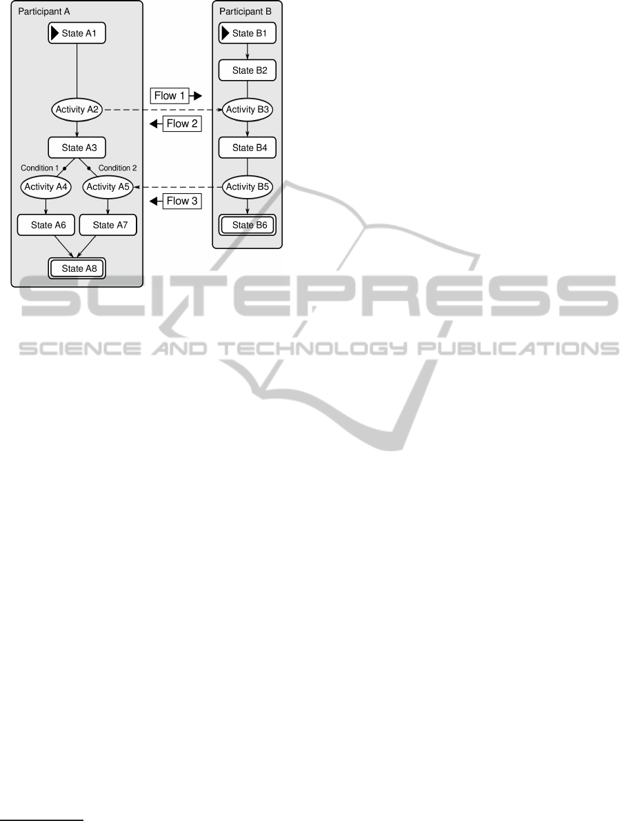
Participant A
State A1
Figure 1: A sample Object Relation Diagram.
transitions from one state to the other. The word
“may” represents our second proposal for the ORD
notation: In the original notation, the activities are
required between the states, which is sometimes not
wanted – analysts
4
then invent artificial activites like
”no action”, etc. Our proposal is nothing more than
incorporating the notion of the ε-transition from the
theory of finite state machines, i.e. a spontaneous
transition from one state into the other.
The purpose of activities is twofold. First, follow-
ing the semantics of the Mealy’s machine, an activity
represents an action which produces some kind of an
output. Such an output may or may not be in fact tan-
gible. In the end, an activity may simply be a task
5
that needs to be done by the participant in order to ad-
vance to the next state. The mere fact, that the task
was done, is being considered as the output.
2.1.2 Communications and Data Flows
The second purpose of the activities is that they allow
participants to communicate with each other. Acti-
vities can be connected by communications (drawn as
horizontal dashed-line arrows). Communications rep-
resent channels for sending outputs of an activity of a
participant to another participant. Such outputs are
called data flows. Data flow is information or an arte-
fact that is sent from a participant to another partici-
pant. The participant containing the activity with the
outward communication arrow is always the initiator
of the communication. Data flows sent by the initiator
4
Let us call the person doing the modelling an “analyst”.
5
We use the term task with the meaning explained in
section 2.
are called input data flows. In reaction, the receiving
participant may send output data flows back to the ini-
tiator.
The original concept of communications in ORD
presumes that both initiating and receiving partici-
pants must be in the initiating and the respective re-
ceiving activity at the same time in order for the com-
munication to take place. We call such a commu-
nication direct. Howerver, in practical applications
of ORD, we often find ourselves in the need for an
indirect communications, as well. A direct commu-
nication models the situation where two interacting
participants need to actually meet each other either
personally, over a phone or using some other direct
medium. On the other hand, if for example Bob writes
an email to Alice, she does not have to wait at the
other end to receive it. The e-mail waits for her un-
til she opens it and Bob may in the meanwhile con-
tinue in his agenda. Thus, this represents our third
proposal: the communication may be marked as in-
direct, which means that the initiator does not have to
wait until the receiver arrives at his receiving activity
and he may go right to the following state. The re-
ceiver, on the other hand, always needs to wait, until
the respective data flow arrives.
2.1.3 Conditions
Transitions may be also restricted by conditions. If
more than one transition comes out of a state, a con-
dition may be placed on any number of the transi-
tions. The participant may go forward along a transi-
tion only when its condition is met. Example of such
a situation is shown in Figure 1. Conditions are used
to express restrictions on decisions of participants and
they are usually expressed in the natural language.
2.1.4 Other Constructs
So far, we have described the basics of ORD seman-
tics and graphical notation. There are also other, more
advanced constructs in ORD. A state, for example,
may contain a nested process; Conditions may be
placed on communications as well. However, we do
not deal with these contructs in this paper, since we
identified that they bring serious complexity to the in-
terpretation and simulation of processes.
2.2 ORD Simulation
Apart from structural aspects of ORD, we need to dis-
cuss the behavioural aspects. In fact, simulation or
execution of processes defined by ORD is the main
challenge of our work. As already mentioned in the
TowardsFormalFoundationsforBORMORDValidationandSimulation
317

Introduction, there is no canonical definition of how
the ORD process should by executed. As far as we
know, the only implementation of ORD simulation is
offered by the Craft.CASE modelling tool.
Figure 2 illustrates the first five steps of simula-
tion of one simple participant, as performed by the
Craft.CASE tool. When the participant is in a par-
ticular state, or it is performing a particular activity,
such state or activity is highlighted with dark grey
background. We say that such a state or activity is
being visited. We see that the participant in the fi-
gure faces a decision at the start state X and chooses
to proceed both of the possible ways simultaneously.
We call such parallel ways branches. This illustration
enables us to inspect the main issues with the simula-
tion of processes defined by ORD.
3 REVISION OF ORD PROCESS
BEHAVIOUR
ORD in the BORM methodology is a simple, yet a
powerful way of describing and visualising business
process. Its semantics can be easily described, es-
pecially to people with little technical knowledge in
process modelling. That, of course, is a great advan-
tage in the business environment. On the other hand,
ORD still suffers from ambiguities in definitions and
that, consequently, causes serious troubles especially
when process simulation and analysis come to play.
3.1 Decision Making and Parallelism
Let us discuss the ambiguities and issues of the ORD
behaviour that we mentioned above. Decision making
and parallelism are the fundamental ones. There
seems to be a lack of agreement on them. On the one
hand, Knott, Merunka and Polak state in (Knott et al.,
2000) that “BOBAs process model is strictly based
on the theory of finite automata”, namely on Mealy’s
machines. On the other hand, Brozek, Merunka and
Merunkova explain in (Brozek et al., 2010) that “vi-
sual simulation of a business process is based on
marked-graph Petri net” – but neither explain how
these two different perspectives should merge to-
gether into a consistent and sound theoretical foun-
dation and interpretation of the process specified by
the ORD.
3.2 The Simultaneity Principle
The basic difference between Petri nets (Peterson,
1981) and Mealy’s machines (Mealy, 1955) lies in the
fact that Petri nets operate on the basis of massive pa-
rallelism, whereas Mealy’s machines, when executed,
always follow one simple path. The Craft.CASE tool
obviously uses Petri nets to simulate processes as doc-
umented by Figure 2. However, this approach im-
poses a serious challenge of an ontologically correct
interpretation of the notion of parallelism. From this
perspective, we propose a notion of the simultaneity
principle:
Principle 1. The simultaneity principle states that
no participant can be split into multiple instances and
thus perform several tasks in parallel.
This principle states that even though any partici-
pant may be in several states at once, no participant
can actually perform several activities at once. The
parallel branches in ORD have, therefore, ontologi-
cally this meaning – the activities belonging to differ-
ent branches do not depend on each other. From that
follows that such activities can be done regardless of
order, which allows one to perform them virtually in
parallel. Therefore, if a participant is required to do
activities in parallel, the actual meaning is that it can
choose to do them in any order desired, or switch be-
tween doing them, as wanted
6
. It is evident that this
concept imposes some constraints on the general be-
haviour of Petri nets, where multiple parallel tokens
are moving independently through the structure of the
net. The simultaneity principle is illustrated in Fi-
gure 2. If the participant A finds itself in the state X,
it faces a decision where to go next. In the next step it
appears to perform both the following activities at the
same time which is, in fact, only a graphical illustra-
tion of the principle described above.
Furthermore, it is necessary to ontologically clarify
what happens once the participant arrives to the state
F. For example, if the participant arrives to F by the
shorter of the two possible branches, should it wait in
F until the other branch is completed as well? If so,
what happens once the participant had chosen only
one branch at the state X? In such a case the process
falls into a deadlock. On the other hand, if we just
follow the Petri net behaviour, no merge is performed
and we get an ontologically extravagant situation as
depicted in 2, where the participant actually arrives to
F multiple times. This is in direct contradiction with
the dependency principle.
The above issue could be solved simply by stating that
F waits only for those branches, that had been actu-
ally chosen. Unfortunately, the nature of this issue
seems to be deeper. When creating a process model,
the analyst should be given a way to explicitly define
6
The situation may be compared to the preemptive mul-
titasking of a computer processor.
ICEIS2014-16thInternationalConferenceonEnterpriseInformationSystems
318

X
Participant A
cond 1
D
cond 2
C
B
E
H
F
G
X
Participant A
cond 1
D
cond 2
C
B
E
H
F
G
X
Participant A
cond 1
D
cond 2
C
B
E
H
F
G
X
Participant A
D
C
B
E
H
F
G
X
Participant A
cond 1
D
cond 2
C
B
E
H
F
G
Step 1 Step 2 Step 3 Step 4 Step 5
cond 1
cond 2
Figure 2: Simulation of a participant facing a decision.
which decisions are valid in a given state and which
are not. For instance, executing several branches may
not be possible in some situations in the reality. In-
stead, a process may require that there is precisely
one of the possible branches that needs to be com-
pleted in order to advance further. Since simultane-
ous and exclusive choices are both valid in process
definition and simulation, we come to the conclusion
that neither Mealy’s machines, nor Petri nets provide
a sufficient formal description of the ORD process be-
haviour.
3.3 The Dependency Principle
Before we introduce the second principle of ORD se-
mantics, we first need to clarify some terminology.
From the perspective of ORD, we talk about states
and activities, states being the primary components of
a participant in the process. When a transition is made
from one state to another, an activity is performed and
we say that the participant completed a task. To iden-
tify that task, we associate it with the state at which
the participant has arrived. So the notions of task and
state will be synonymous from our point of view.
Above, we already informally touched the notion
of the task dependency, which is a very essential
principle of process definition regardless of particular
methodology. The terms “interrelated and interact-
ing” in Definition 1 denote the fact that often several
tasks have to be completed prior to completing an-
other task. From now on, we refer to this principle as
the dependency principle:
Principle 2. The dependency principle states that a
task A may require other task to be completed before
A can be completed.
The rules that determine on which tasks the task A
depends, may be quite complex. Let us have a set of
tasks {X, Y, Z}. For example, the task A may require
a completion of exactly two tasks from this set. Thus,
we need a sufficiently expressive system for specify-
ing such dependency conditions – we introduce such
a system utilising boolean algebra in the next section.
4 INPUT/OUTPUT CONDITIONS
Having explained the main challenges, we may start
formulating new formal foundations of the ORD. We
start by introducing the concept of input and output
conditions, which incorporates the dependency prin-
ciple into the ORD and targets the formalisation of the
simultaneity principle.
4.1 Input and Output Conditions
To be able to express the dependency principle in an
ORD, we attach an input condition to each state:
Definition 2. Input condition of a state is a boolean
expression whose variables are the transitions ending
in that state. It specifies that the execution of the pro-
cess cannot advance further from the given state until
its input condition is met, i.e. until the corresponding
boolean expression is evaluated as being true.
Similarly, each state also has an output condition.
Definition 3. Output condition is a boolean expres-
sion whose variables are the outgoing transitions from
the given state. It specifies admitted combinations of
branches into which the process execution may split
itself from this state.
Figure 3 shows an example of input and output
TowardsFormalFoundationsforBORMORDValidationandSimulation
319

conditions allowing precisely two distinct paths
through the participant’s state graph. State A has
an output condition which says that exactly one of
two possible transitions may be chosen to continue
forward. The state D has, in turn, an input condition
saying, that exactly one branch is allowed to com-
plete.
Participant
State A
Figure 3: Sample input and output conditions.
The input condition of a state is interpreted as fol-
lows: When several branches merge in one state, then
this state waits for all of them to complete and only
then evaluates its input condition. If the condition
is met, the participant may advance to the next state,
otherwise the process fails.
The output conditions, on the other hand, en-
sure that when the process flow splits into several
branches, only the appropriate branches are allowed
to be chosen, i.e. the branches that do not allow the
process to fail – falling into deadlock. Therefore, in-
put and output conditions provide a solution to ad-
dressing both the simultaneity and the dependency
principles. Since each state waits for all the branches
to complete before evaluating its input condition, it
prevents the situation, where the participant would
split into several independent instances, because one
branch took more steps to complete. Moreover, each
state now specifies exactly on what branches it de-
pends and thus perfectly expresses the dependency
principle.
5 DISCUSSION
The solution of the issues with ORD process be-
haviour interpretation and simulation proposed here
lies in the introduction of the input/output conditions
of states. The solution has the following features:
1. Input/output condition are expressions in boolean
logic and therefore general and unambiguous.
2. They address both the simultaneity and depen-
dency principle.
3. No additional elements in the ORD are needed,
so the diagrams remain clear and simple as was
intended by the authors.
6 RELATED WORK
As we stated above, we are not aware of any sys-
tematic effort to build formal foundations of BOBA.
Given that, our work is very likely quite novel for
BORM. However, looking at model execution, sim-
ulations and behaviour analysis from a broader per-
spective, we may identify other attempts similar to
ours – and at these, we want to look at now. There
are generally two complementary approaches:
1. Start with a formal apparatus and build a practi-
cally applicable domain-oriented method and/or
tool.
2. Start with a method used in practice and upgrade
it into a simulation-able or an executable model.
Starting with the first type of approach, Brand’s
and Zafiropulo’s Communicating Finite State Ma-
chines are an example. Their purpose was to de-
sign communication protocols (Brand and Zafirop-
ulo, 1983). The authors took the finite state machines
(FSM) theory and upgraded it consistently for mod-
elling several together-bound FSMs. Another exam-
ple of such an approach is Pattavita’s and Trigila’s
proposal to combine the FSM with Petri nets for mod-
elling communicating processes (Pattavina and Trig-
ila, 1984). Another example is the Yasper tool for
workflow modelling and analysis (van Hee et al.,
2006); it is based on Petri nets enriched by several
practical concepts from the domain of process analy-
sis (hierarchies, choices, roles and others).
The second mentioned approach, i.e. to upgrade
an existing method, is exemplified by our work. Kin-
dred spirit to ours is Barjis: he proposed a method for
developing executable models of business systems.
Barjis’ method is based on the DEMO method (Di-
etz, 2006). To make the static DEMO models exe-
cutable, Barjis proposed a transformation into Petri
nets (Barjis, 2007). His insight has been recently fol-
lowed by, for instance, Vejrazkova and Meshkat (Ve-
jrazkova and Meshkat, 2013).
We are also aware of similar approaches focused
on standard ”industry” notations UML and BPMN.
In spite of general popularity of these notations, we
do not deal with them, as they suffer from vagueness,
ambiguities and ontological flaws, as mentioned by
e.g. Silver in (Silver, 2011) or Dijkman et al. in (Di-
jkman et al., 2008). Guizzardi performed a deep anal-
ysis of BPMN suitability for expressing simulation
ICEIS2014-16thInternationalConferenceonEnterpriseInformationSystems
320

models in (Guizzardi and Wagner, 2011) with quite
discouraging results for researchers and practitioners
focused on ontological soundness of modelling.
Though we could continue in compiling a list of
similar approaches, our goal was just to document
that a combination of a practical approach with a ro-
bust formal foundation leads to a new level of under-
standing of modelling methods, improving their ex-
pressiveness, power and, ultimately, their usefulness.
7 FUTURE WORK
As implied by the title of the paper, our goal was just
to make first steps towards sound formal foundations
of BORM. The future work means to specify a com-
plete formalism for ontologically sound executionand
simulation of processes defined by ORD. This formal-
ism should encompass the needed features of Mealy’s
machine and Petri nets, while at the same time not al-
lowing ontologically extravagant situations.
In this paper, we omitted advanced ORD con-
structs (communication conditions and nested pro-
cesses). These constructs should be also studied in
the future work.
8 CONCLUSION
We described the syntax and semantics of BORM Ob-
ject Behaviour Analysis (BOBA) – Object Relation
Diagrams (ORD). We discussed the main issues and
ambiguities of the ORD semantics with the respect
to execution and simulation of processes defined by
ORD. We proposed minor changes and enhancements
for the model. Then, as the first step towards a sound
formalisation of BOBA, we introduced the input and
output conditions enhancement for states.
Our honest hope is that our contribution may be
an inspiration for both BORM practitioners and for-
malists to join their forces to bring BOBA to a new
level of expressive power and possibilities.
REFERENCES
Barjis, J. (2007). Developing executable models of busi-
ness systems. Setubal. Insticc-Inst Syst Technologies
Information Control & Communication.
Brand, D. and Zafiropulo, P. (1983). On communication
finite-state machines. Journal of the ACM, 30(2):323–
342.
Brozek, J., Merunka, V., and Merunkova, I. (2010). Or-
ganization modeling and simulation using BORM ap-
proach, volume 63 of Lecture Notes in Business Infor-
mation Processing.
Dietz, J. L. G. (2006). Enterprise ontology: theory and
methodology. Springer, Berlin; New York.
Dijkman, R. M., Dumas, M., and Ouyang, C. (2008). Se-
mantics and analysis of business process models in
bpmn. Inf. Softw. Technol., 50(12):1281–1294.
Guizzardi, G. and Wagner, G. (2011). Can BPMN be
used for making simulation models? Lecture Notes
in Business Information Processing, 88 LNBIP:100–
115. 00004.
Knott, R., Merunka, V., and Polak, J. (2000). Process mod-
eling for object oriented analysis using BORM ob-
ject behavioral analysis. In 4th International Con-
ference on Requirements engineering, 2000. Proceed-
ings, pages 7–16.
Knott, R., Merunka, V., and Polak, J. (2003). The BORM
methodology: a third-generation fully object-oriented
methodology. Knowledge-Based Systems, 16(2):77–
89.
Mealy, G. H. (1955). A method for synthesizing sequential
circuits. Bell System Technical Journal, 34(5):1045–
1079.
Merunka, V. (2010). Object-oriented proces modeling and
simulation – borm experience. Trakia Journal of Sci-
ences, 8(3):71–87.
Merunka, V. (2012). FSM-Based object-oriented organiza-
tion modeling and simulation. In Aalst, W., Mylopou-
los, J., Rosemann, M., Shaw, M. J., Szyperski, C., Ba-
jec, M., and Eder, J., editors, Advanced Information
Systems Engineering Workshops, volume 112, pages
398–412. Springer Berlin Heidelberg.
Merunka, V. and Merunkova, I. (2013). Role of OBA ap-
proach in object-oriented process modelling and sim-
ulation. In Barjis, J., Gupta, A., and Meshkat, A.,
editors, Enterprise and Organizational Modeling and
Simulation, volume 153 of Lecture Notes in Business
Information Processing, pages 74–84. Springer Berlin
Heidelberg.
Merunka, V. and Molhanec, M. (2011). BORM: agile mod-
elling for business intelligence. In Rahman El Sheikh,
A. A. and Alnoukari, M., editors, Business Intelli-
gence and Agile Methodologies for Knowledge-Based
Organizations: Cross-Disciplinary Applications. IGI
Global.
Merunka, V., Nouza, O., and Broek, J. (2008). Automated
model transformations using the C.C language. In Di-
etz, J., Albani, A., and Barjis, J., editors, Advances in
Enterprise Engineering I, volume 10 of Lecture Notes
in Business Information Processing, pages 137–151.
Springer Berlin Heidelberg.
Pattavina, A. and Trigila, S. (1984). Combined use of finite-
state machines and petri nets for modelling commu-
nicating processes. Electronics Letters, 20(22):915–
916.
Pergl, R. (2011). Supporting enterprise IS modelling using
ontological analysis. Lecture Notes in Business Infor-
mation Processing, 88:130–144.
Pergl, R. and Tuma, J. (2012). OpenCASE – a tool
for ontology-centred conceptual modelling. Lecture
Notes in Business Information Processing, 112:511–
518.
TowardsFormalFoundationsforBORMORDValidationandSimulation
321

Peterson, J. L. (1981). Petri net theory and the modeling of
systems. Prentice Hall.
Silver, B. (2011). BPMN Method and Style, 2nd Edition,
with BPMN Implementer’s Guide: A structured ap-
proach for business process modeling and implemen-
tation using BPMN 2.0. Cody-Cassidy Press.
Struska, Z. and Merunka, V. (2007). BORM points - new
concept proposal of complexity estimation method.
In Cardoso, J., Cordeiro, J., and Filipe, J., editors,
Proceedings of the ninth international conference on
enterprise information systems, pages 580–586. IN-
STICC.
Struska, Z. and Pergl, R. (2009). BORM-points: introduc-
tion and results of practical testing. Lecture Notes in
Business Information Processing, 24:590–599.
van Hee, K., Oanea, O., Post, R., Somers, L., and van der
Werf, J. (2006). Yasper: a tool for workflow model-
ing and analysis. In Sixth International Conference on
Application of Concurrency to System Design, 2006.
ACSD 2006, pages 279 –282.
Vejrazkova, Z. and Meshkat, A. (2013). Translating
DEMO models into petri net. In Enterprise and Or-
ganizational Modeling and Simulation, volume 153.
Springer Verlag Heidelberg.
ICEIS2014-16thInternationalConferenceonEnterpriseInformationSystems
322
