
A COMPUTATIONALLY EFFICIENT GUIDANCE SYSTEM FOR A
SMALL UAV
Guillaume Ducard and Hans P. Geering
ETH Zurich, Measurement and Control Laboratory, 8092 Zurich, Switzerland
Keywords:
Efficient path planning, adaptive guidance algorithm, unmanned aircraft, obstacle avoidance.
Abstract:
In this paper, a computationally efficient guidance algorithm has been designed for a small aerial vehicle.
Preflight path planning only consists of storing a few waypoints guiding the aircraft to its target. The paper
presents an efficient way to model no-fly zones and to generate a path in real-time in order to avoid the
obstacles, even in the event of wind disturbance.
1 INTRODUCTION
Motion planning has been extensively studied over
the last decade, especially in the context of ground
robots. Path-planning methods based on potential
field functions present the difficulty of choosing an
appropriate potential function, and the algorithm may
be stuck at some local minima (Koren and Borenstein,
1991). The Probabilistic Road Maps (PRM) method
(Kavraki et al., 1996) explores all the possible paths
within the configuration space, and finally selects the
lower cost route. However, the computational load
makes the PRM method impractical for real time
path planning in small UAVs. An extension to the
PRM method is presented in (Amin et al., 2006) and
is called modified Rapidly-exploring Random Trees
(RRT), which is capable of efficiently searching for
feasible paths in the space taking into account con-
straints from the vehicle performance. However, ef-
forts are still going on to implement a path replan-
ning on-the-fly as pop-up obstacles are discovered, or
when the performance of the vehicle degrade. Other
path-planning techniques are based on optimization
methods, such as Mixed Integer Linear Programming
(Schouwenaars et al., 2005) or Model Predictive Con-
trol techniques (Kuwata et al., 2006), which still in-
volve heavy computations.
This paper presents a guidance algorithm for an
unmanned aerial vehicle (UAV), which generates on-
line a flight path based on predefined waypoints,
avoids known or appearing obstacles, is simple to im-
plement and requires very low computational power.
The complete guidance system is intended to run on
small microcontrollers with limited floating point op-
erations capability.
Most of the research dealing with obstacle avoid-
ance seems to be directed towards advanced, rel-
atively complex methods. These methods, mainly
based on optimization algorithms, are appropriate for
larger UAVs with sufficient processing power onboard
or for systems where the data processing can be done
at a base station with the flight path being relayed up
to the aircraft. The work of this paper focuses on
highly simplified methods for real-time path gener-
ation in order to avoid no-fly zone (NFZ).
Section II of this paper describes how the aircraft
autonomously detects whether any approaching NFZs
are a threat. Section III presents a strategy to avoid the
NFZ, and Section IV considers cases of wind distur-
bances, and shows how the guidance algorithm still
allows the aircraft to avoid the NFZ.
2 GUIDANCE CONTROL LAW
The control law used in the guidance algorithm is
based on work done in (Park, 2004) and (Park et al.,
2004). The control law chooses a reference point that
is on the desired path and a distance L
1
ahead of the
aircraft. It then calculates the angle between the air-
craft’s velocity vector and the line L
1
to generate a
lateral acceleration command a
s
using (1), which is
converted into a bank angle command φ
com
using (2).
This control law is especially suited to follow curved
paths, such as circles, and is also efficient to track
124
Ducard G. and P. Geering H. (2007).
A COMPUTATIONALLY EFFICIENT GUIDANCE SYSTEM FOR A SMALL UAV.
In Proceedings of the Fourth International Conference on Informatics in Control, Automation and Robotics, pages 124-130
DOI: 10.5220/0001630001240130
Copyright
c
SciTePress
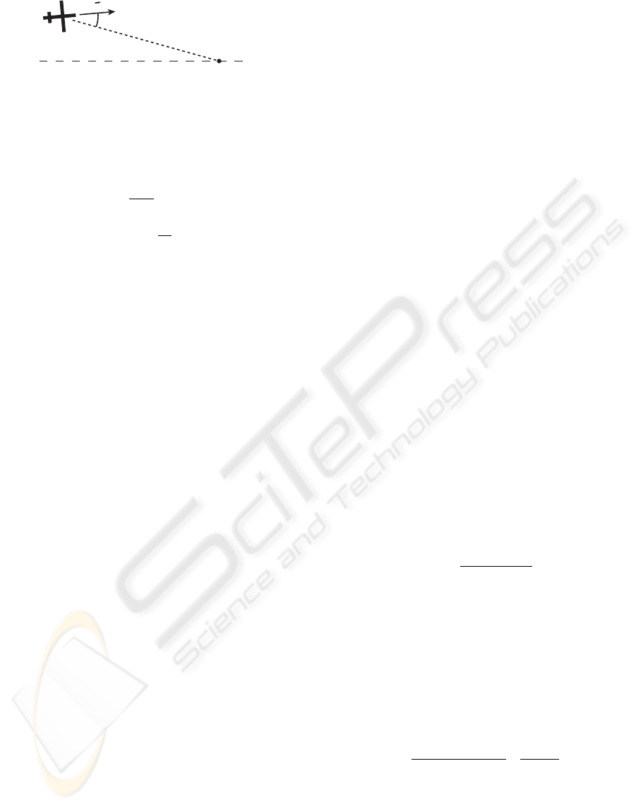
L
1
Desired
Path
V
Figure 1: Diagram of Control Law Geometry.
straight line segments.
a
s
=
2V
2
L
1
sin η (1)
φ
com
≈
a
s
g
(2)
3 NO-FLY ZONES
3.1 Definition of a No-Fly Zone
A no-fly zone is any airspace that an aircraft is not
permitted to fly in. This airspace can be of any arbi-
trary shape. In order to simplify the guidance algo-
rithm, two conditions are imposed on how the NFZ is
represented.
First, the vertical limits of the NFZ are not consid-
ered so that the NFZ is essentially a two-dimensional
surface. The aircraft is not allowed to pass over or
under the NFZ.
Second, the shape of the NFZ is chosen to be a
circle. In this way, the avoidance maneuver can be an
arc of a circle in order to benefit from the guidance
control law especially suited to track circles, which
are described by only two parameters, their center and
their radius.
Although this paper only discusses the avoidance
of one circular NFZ, the algorithm can be extended
to multiple no-fly zones with some simple modifica-
tions. Also, a complex no-fly zone shape can be rep-
resented by multiple circles.
Before the flight, the location of the known no-
fly zones to be encountered during the mission are
stored in the memory of the autopilot. If the UAV is
equipped with scanning sensors that can detect pop-
up obstacles, their position can be taken into account
by the path-planning system to recompute on the fly a
new trajectory that avoids the threat and continues the
mission as soon as possible.
In order to determine whether an NFZ or an ob-
stacle interferes with the planned path, an imaginary
“detection line” is used. It has a length R
LA
and is
located in front of the aircraft, as shown in Fig. 2.
3.2 Definition of the Look-ahead
Distance R
LA
The distance R
LA
defines the so-called “look-ahead
distance”. If any part of this detection line penetrates
an NFZ or an obstacle, avoidance action is immedi-
ately taken as described in the next section.
The guidance algorithm determines whether a
NFZ interferes with the planned path using current
aircraft position, velocity, and aircraft performance
information such as the maximum bank angle that is
allowed φ
max
. Although the location of an NFZ is
known to the guidance algorithm, the guidance algo-
rithm will only take action if the NFZ is an immediate
obstacle.
An NFZ is considered to be an immediate obstacle
if any part of it is touched by the imaginary “detection
line” of length R
LA
in front of the aircraft.
Choosing a good value for R
LA
is important. Too
large of a value will cause the guidance algorithm to
take unneeded action or to take action too early, while
too small of a value will not allow the aircraft enough
time to maneuver away from the NFZ without pene-
trating it.
R
LA
is chosen such that the aircraft will fly an arc
that stays just outside the NFZ at the point of closest
approach, which means that the turn was started as
late as possible. R
LA
depends on the radius of the
NFZ, R
NF Z
, the ground speed of the aircraft V , and
the maximum bank angle of the aircraft φ
max
.
Given these parameters, and assuming a coordi-
nated turn, the minimum turn radius the aircraft can
fly is given by
R
min
=
V
2
g tan(φ
max
)
. (3)
In the case of a NFZ with infinite radius, the air-
craft would have to make a 90
◦
turn, in which case
R
LA,min
= R
min
. For any NFZ with a finite radius,
the aircraft has to turn less than 90
◦
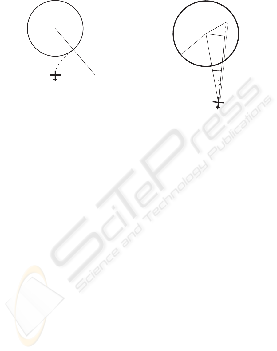
to avoid it. As-
suming that the path of the turning aircraft is tangent
to the edge of the NFZ, a triangle can be set up as
shown in Fig. 2, with vertices at the center of the
NFZ, at the aircraft, and at a point R
min
off the right
wing-tip. The aircraft is at the point where it must
begin its turn. R
LA,min
is then given by
R
LA,min
=
p
2R
min
+ R
NF Z
p
R
NF Z
− R
NF Z
.
(4)
To obtain the final value for R
LA
, compensation
must be made for the delay needed to initiate the turn,
including the time to roll to φ
max
. The delay needed
to initiate the turn, τ
roll
, is compensated for by adding
a representative distance to R
LA,min
. The assump-
tion is made that while the aircraft is initiating the turn
A COMPUTATIONALLY EFFICIENT GUIDANCE SYSTEM FOR A SMALL UAV
125
R
m
i
n
R
m
i
n
R
N
F
Z
R
N
F
Z
R
L
A
Figure 2: Diagram of R
LA
.
it continues to fly level, and then as soon as it reaches
φ
max
it makes a minimum radius turn. The charac-
teristic time τ
roll
can be multiplied by the aircraft’s
speed to get the distance the aircraft will travel during
this delay, which is added to R
LA,min
.
The resulting look-ahead distance is
R
LA
= R
LA,min
+ V τ
roll
. (5)
3.3 Detection of the No-Fly Zone
As mentioned before, the algorithm monitors a line
ahead of the aircraft. First, the distance D
NF Z
from
the aircraft to the center of the NFZ is calculated.
D
NF Z
≤ R
NF Z
+ R
LA
(6)
If the condition set in (6) is satisfied, where R
NF Z
is the radius of the NFZ, then the aircraft is considered
to be within range of the NFZ. In this case, a further
check is made to see if a part of the NFZ is touching
the detection line.
For the second check, there are two possible cases,
depending on the position of the aircraft. A pair of
triangles is created as shown in Fig. 3 or Fig. 4. The
edges h and R
LA
, and the angle α are known. The
length of edges y and a can easily be calculated, using
y = h sin(α )
a = h cos(α). (7)
Case 1 applies if a ≤ R
LA
. The limiting case is
when edge a is tangent to the NFZ, in which case y
will have a length equal to R
NF Z
. Thus, the NFZ
touches the detection line if
y ≤ R
NF Z
.
Case 2 applies if a > R
LA
. The limiting case
occurs when the end of the detection line is on the
edge of the NFZ. This can be checked by comparing
V
x
R
NFZ
h
R
LA
y
a
Figure 3: Diagram of NFZ Detection Algorithm, Case 1
(detected).
the length of the edge x to the radius of the NFZ, so
that the detection line touches the NFZ if
x ≤ R
NF Z
, (8)
where
x =
p
y
2
+ (a − R
LA
)
2
. (9)
The check for Case 1 or Case 2 is only done if α
is less than or equal to 90
◦
. If α is greater than 90
◦
,
then the center of the NFZ lies behind the aircraft and
no action is taken.
The no-fly zone detection method that was pre-
sented provides sufficiently early notice of any im-
pending NFZ penetration for the guidance algorithm
to take action to avoid the NFZ. The algorithm for
avoiding the NFZ is described in the following sec-
tion.
4 NO-FLY ZONE AVOIDANCE
ALGORITHM
The no-fly zone avoidance algorithm guides the air-
craft around any NFZ that the aircraft encounters. The
avoidance method is designed to be simple to imple-
ment while allowing the aircraft to reach waypoints
close to the edge of the no-fly zone.
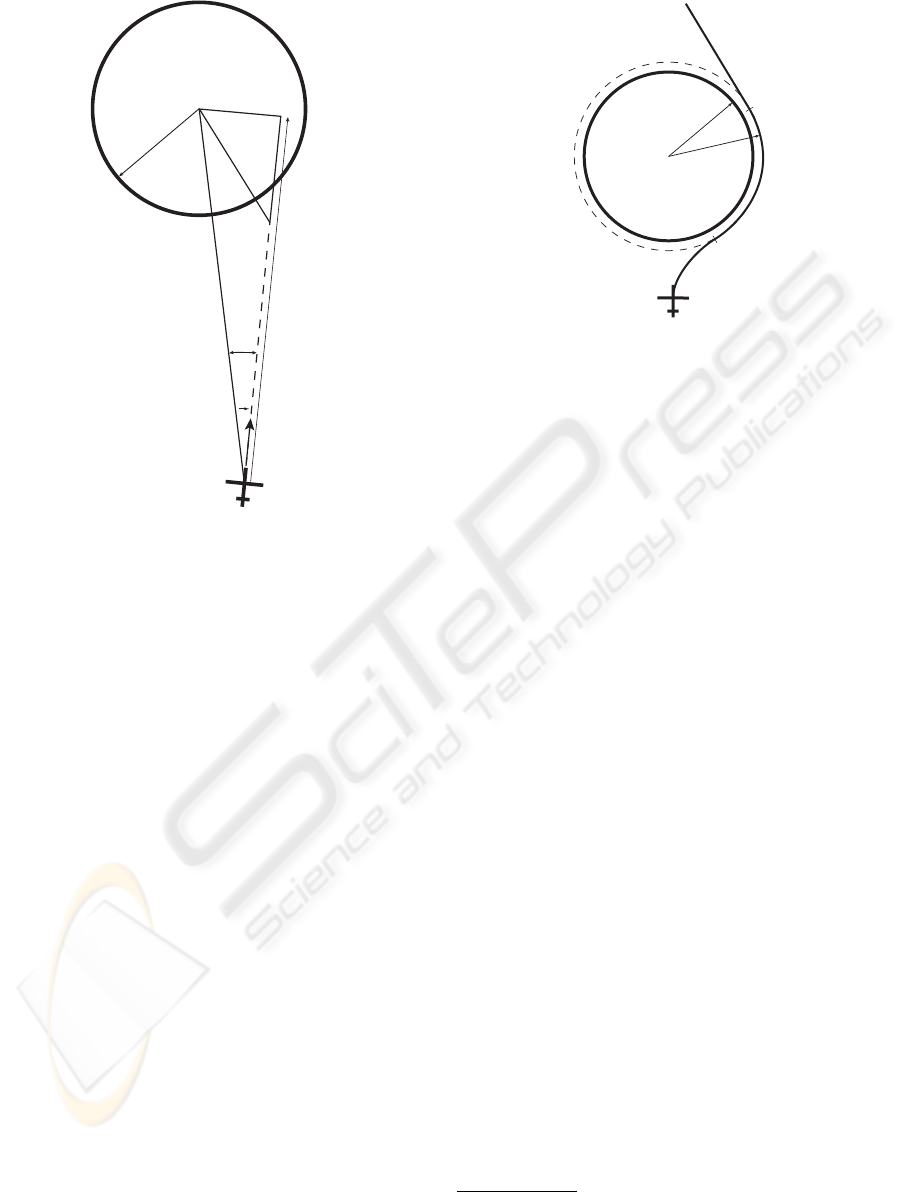
4.1 Path Template
One key feature of this avoidance method is the selec-
tion of a circular arc around the NFZ as a reference
path. Such a path minimizes the distance the aircraft
flies to avoid the NFZ. Moreover, we saw at the begin-
ning of this chapter that our lateral guidance control
ICINCO 2007 - International Conference on Informatics in Control, Automation and Robotics
126
V
x
R
NFZ
h
R
LA
y
a
Figure 4: Diagram of NFZ Detection Algorithm, Case 2
(not detected).
law is particularly efficient in tracking such a path.
Choosing the reference path to be circular allows the
path to be easily defined in relationship to the NFZ
dimensions.
The aircraft follows this path until it is able to con-
tinue towards the next waypoint in a straight line and
without passing through the NFZ. As shown in Fig.
5, the arc has the same center as the NFZ but has a
slightly larger radius. The distance between the refer-
ence path and the edge of the NFZ serves as a safety
margin against deviations the aircraft makes from the
reference path.
No complex calculations have to be made to de-
termine where the path lies; it is defined by the center
of the NFZ and a path radius, R
1
, which is simply the
NFZ radius plus a safety margin. R
1
must be chosen
to be larger than or equal to the minimum turn radius
of the aircraft, such that the reference path represents
a feasible path. Also, the point at which the guid-
ance algorithm transitions back to normal guidance
towards the next waypoint is easily chosen. This tran-
sition occurs when there is a clear line-of-sight from
the aircraft’s current position to the next waypoint.
4.2 Relevant Control Law Properties
The properties of the chosen control law used in the
guidance algorithm, namely its inherent ability to fol-
x
R
NFZ
R
1
Next
Waypoint
T
1
T
2
T
3
Figure 5: Avoidance Path Template.
low a circular path, make the chosen path easy to fol-
low. As shown in (Park, 2004), the aircraft is able
to follow a circle without any steady-state error, even
with wind. This is because the bank angle command
given by the controller causes the aircraft to fly an arc
that is tangent to the aircraft’s current velocity and
that crosses the reference path at a given distance in
front of the aircraft. In the case of a circular reference
path, the proper bank angle command is given so that
the aircraft flies exactly along the this reference path.
When the aircraft is on the reference path and flying
along it, the bank angle that is commanded provides
the right lateral acceleration to fly a circle of the same
radius as the reference path. When the aircraft is off
the reference path, the bank angle command is such
that the aircraft will converge with the reference path.
4.3 Avoidance Guidance Schedule
Upon detecting a no-fly zone, the aircraft initiates a
maximum bank turn either to the left or right and then
flies around the NFZ along the reference path. This
method allows the guidance algorithm to initiate the
avoidance maneuver as late as possible. This is de-
sirable since it makes more waypoints reachable than
if the avoidance maneuver were started earlier. The
only unreachable waypoints are those that lie within a
radius of R
NF Z
+ R
LA
from the center of the NFZ
1
.
4.3.1 Choice of Avoidance Side, T
1
Whether the guidance algorithm chooses to go left or
right around the NFZ is determined by which side of
the NFZ center the aircraft is already flying towards.
1
In the case of approaching a NFZ head-on, the guidance
algorithm begins its avoidance maneuver when it reaches a
distance of R
N F Z
+ R
LA
.
A COMPUTATIONALLY EFFICIENT GUIDANCE SYSTEM FOR A SMALL UAV
127
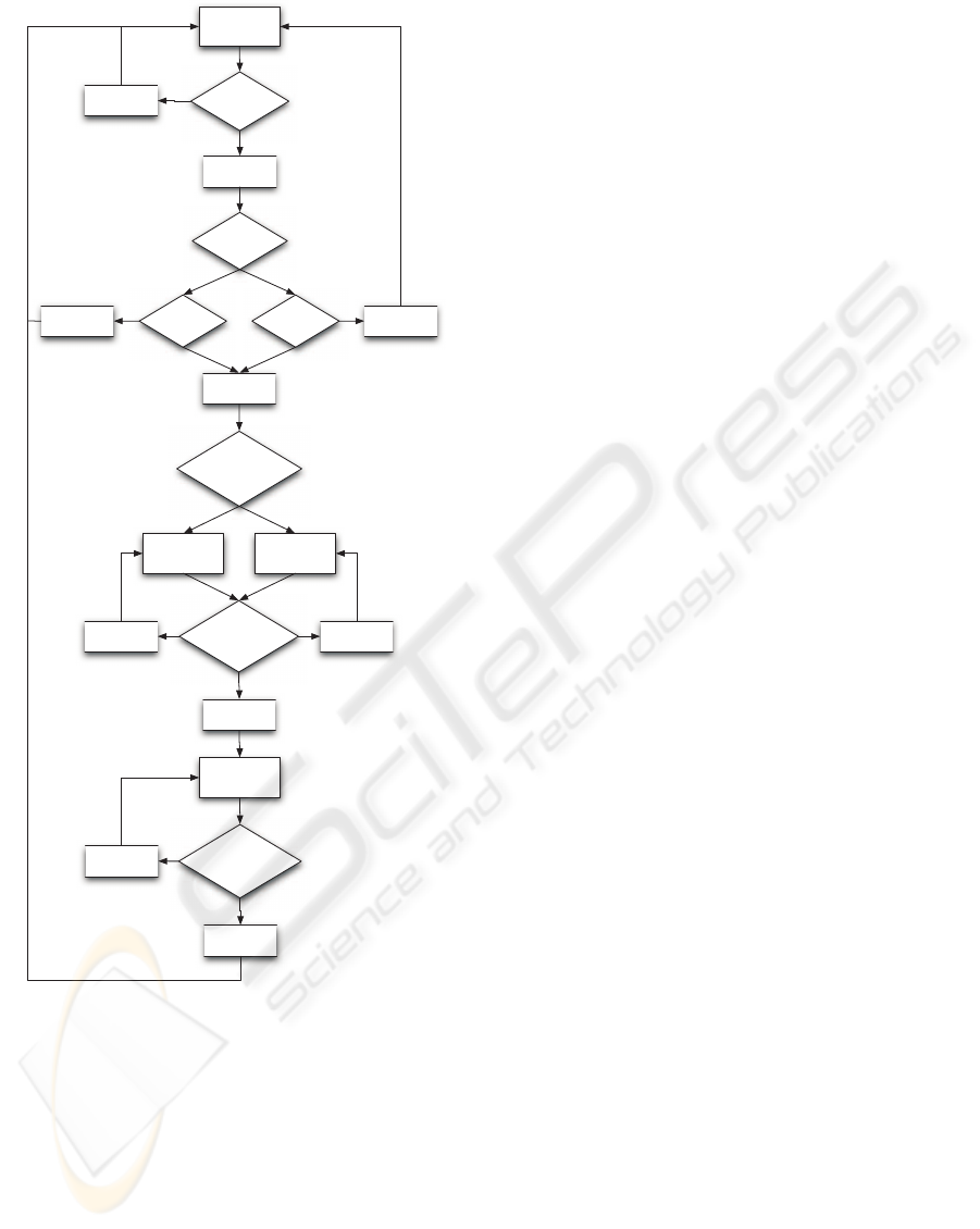
NormalWaypoint
Tracking
IsNFZwithin
R_LA Of
Aircraft?
YES
NO
ToWhichSideOf
NFZisVelocity
VectorPointing?
LEFT
MinimumRadius
Turn To TheLeft
RIGHT
MinimumRadius
Turn To TheRight
IsVelocityVector
PointingOutsideOf
NFZ?
NO NO
YES
Follow Arc Around
NFZ
UnobstructedLine-
Of-Sight ToNext
Waypoint?
NO
YES
DoesCase1or
Case2 Apply?
YES
Case1:Is
y<=R_NFZ?
Case2:Is
x<=R_NFZ?
NONO
Figure 6: Finite State Diagram of Avoidance Algorithm.
If the aircraft’s velocity vector is pointing to the right
of the NFZ center, then the aircraft will fly around the
right side of the NFZ. If the velocity vector is pointing
to the left side, then the aircraft flies around the NFZ
on the left side. A circular NFZ makes this decision
easy.
4.3.2 Transition to Reference Path, T
2
Once the aircraft begins its turn, it continues to turn
until its velocity vector is tangent to, or points outside
of the NFZ. At this point the guidance switches to
following the circular reference path.
4.3.3 Transition to Normal Waypoint Tracking,
T
3
Once the aircraft is following the reference path, it
will continue to do so until it has a line-of-sight to
the next waypoint that is unobstructed by the NFZ.
At this “switchover point”, the guidance switches
out of avoidance mode and guides the aircraft to the
next waypoint. It follows a reference line from the
switchover point to the next waypoint. Once the next
waypoint is reached, guidance continues as normal.
A possible alternative solution is to avoid the obsta-
cle and then follow again the original reference path
that passed through the no-fly zone, but this makes the
aircraft fly a longer path to finally reach the desired
waypoint.
4.4 Properties of the Guidance Schedule
The presented guidance schedule has several desir-
able properties. It attempts to minimize the number
of waypoints that are unreachable, it avoids complex
logic to decide how to avoid the no-fly zone, and it
minimizes the time and distance to return to the orig-
inal flight path.
4.4.1 Minimizing Unreachable Waypoints
The guidance schedule minimizes the number of un-
reachable waypoints by initiating the avoidance ma-
neuver as late as possible. A waypoint is deemed un-
reachable if it cannot be flown over while following
the original path and without causing the aircraft to
penetrate the NFZ. Waypoints within R
1
of the center
of the NFZ are unreachable.
4.4.2 Avoiding Complex Logic
The guidance schedule avoids complex logic. The
main decisions that have to be made are when to be-
gin the avoidance maneuver, which side to fly around
the NFZ, and when to begin flying directly to the next
waypoint. The first decision is made by the NFZ de-
tection algorithm; the avoidance maneuver begins as
soon as the NFZ is detected, which is when the air-
craft is within a distance of R
LA
of the NFZ edge.
The side around which the NFZ is circumnavigated is
chosen simply by the side to which the velocity vector
of the aircraft points at the time the decision is made.
In the case of the aircraft approaching the NFZ head-
on, the decision can be made arbitrarily. The final de-
cision is also simple, in that the aircraft continues on
ICINCO 2007 - International Conference on Informatics in Control, Automation and Robotics
128
to the next waypoint when it has a clear line-of-sight
to it. A clear line-of-sight can be checked by using
an algorithm similar to the NFZ detection algorithm,
but with the “detection line” pointed towards the next
waypoint, instead of ahead of the aircraft.
4.4.3 Minimizing Time and Distance to Return
to Original Flight Path
After the avoidance maneuver is initiated, the goal
of the guidance algorithm is to minimize the distance
and time to return to the original flight plan. It does
this by flying directly to the next waypoint after the
NFZ as soon as is safely possible. A possible down-
side of this is that it may create an excessively sharp
turn leaving the waypoint, but the control law is able
to handle even sharp turns (with an overshoot that
most control laws would have).
5 SIMULATION
5.1 Simulation Setup
Simulations were done on a nonlinear 6-DOF com-
puter model of a radio controlled aerobatic aircraft.
The model has a 4-axis low-level autopilot which al-
lows to directly give the autopilot a bank angle com-
mand. The airspeed, altitude, and side-slip are kept
constant.
5.2 Simulation Scenario
Three similar scenarios were simulated with the re-
sults presented below. In all scenarios, the aircraft is
following a desired path that passes through a no-fly
zone. The simulation was done with maximum banks
angles of φ
max
= 30
◦
.
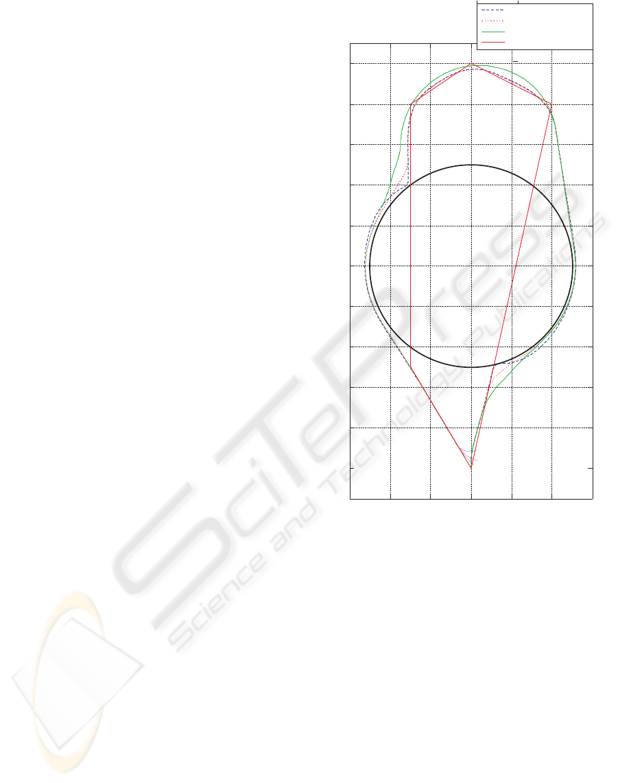
5.3 Simulation Results
5.3.1 No Wind
This first scenario, shown in Fig. 7, highlights the ba-
sic response of the aircraft to a NFZ blocking its path.
The aircraft begins south of the NFZ and flies north
along the desired path defined by the waypoints 1 to
5 and returns back to the runway. The desired path
passes through a no-fly zone, but the aircraft deviates
around it before returning to the desired path. The
simulation was run at three different flight speeds, 15,
30, and 45 m/s. It can be seen that the aircraft begins
its turn much later when flying at 15 m/s than when
-600 -400 -200 0 200 400 600
0
200
400
600
800
1000
1200
1400
1600
1800
2000
East[m]
North [m]
15m/s
30m/s
45m/s
PaththroughWaypoints
1
2
3
4
5
Figure 7: Obstacle avoidance in no wind condition at dif-
ferent speeds.
flying at 45 m/s. The airplane stays outside the no-fly
zone at all three speeds.
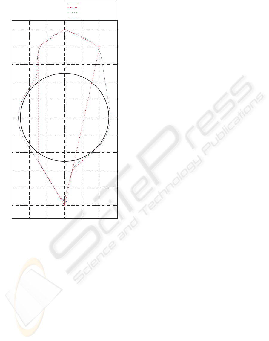
5.3.2 With Wind
This second scenario, shown in Fig. 8, highlights the
response of the aircraft in wind conditions. The de-
sired path remains the same as in the first scenario.
The path taken by the aircraft without wind and with
wind are shown for comparison. The aircraft is flying
at a nominal airspeed of 30 m/s.
A first flight is made with a 6 m/s crosswind
blowing from east to west. In this case, the path fol-
lowed by the aircraft is almost identical to the one
without wind.
Another flight simulation is made with wind blow-
ing from south to north with a speed of 6 m/s. The
A COMPUTATIONALLY EFFICIENT GUIDANCE SYSTEM FOR A SMALL UAV
129
-600 -400 -200 0 200 400 600
0
200
400
600
800
1000
1200
1400
1600
1800
2000
East[m]
North [m]
nominalpath
withnorthwind6m/s
withEastwind6m/s
PaththroughWaypoints
Figure 8: Obstacle avoidance in wind conditions.
trajectory in the latter windy condition differs from
the the nominal track (without wind) in the two turns
that avoid the obstacle, where there is a maximum dif-
ference of 20 m.
In both cases the no-fly zone is avoided. After
the obstacle has been avoided, the guidance system
resumes normal waypoint tracking.
6 CONCLUSIONS
This paper presented a guidance algorithm that com-
bines simplicity and the ability to avoid no-fly zone.
The algorithm successfully demonstrated in simula-
tion its ability to guide the aircraft around the no-fly
zone and then to resume flying along the desired path.
It demonstrated this ability in wind conditions. Fi-
nally, the method is computationally efficient.
REFERENCES
Amin, J. N., Boskovic, J. D., and Mehra, R. K. (2006). A
fast and efficient approach to path planning for un-
manned vehicles. In Proceedings of AIAA Guidance,
Navigation, and Control Conference, Keystone, Col-
orado.
Kavraki, L., Svestka, P., Latombe, J., and Overmars, M.
(1996). Probabilistic roadmaps for path planning in
high-dimensionnal configuration spaces. IEEE Trans-
actions on Robotics and Automation, 12(4).
Koren, Y. and Borenstein, J. (1991). Potential fields meth-
ods and their inherent limitations for mobile robot
navigation. In Proceedings of IEEE Conference on
Robotics and Automation, Sacramento, CA.
Kuwata, Y., Richards, A., Schouwenaars, T., and How, J.
(2006). Decentralized robust receding horizon con-
trol for multi-vehicle guidance. In Proceedings of
IEEE American Control Conference, pages 2047–
2052, Minneapolis, Minnesota.
Park, S. (2004). Avionics and Control System Development
for Mid-Air Rendez-vous of Two Unmanned Aerial Ve-
hicles. Ph.D. thesis, Department of Aeronautics and
Astronautics, Massachusetts Institute of Technology,
Available at http://hdl.handle.net/1721.1/16662, Cam-
bridge, Massachusetts.
Park, S., Deyst, J., and How, J. (2004). A new nonlinear
guidance logic for trajectory tracking. In AIAA Guid-
ance, Navigation, and Control Exhibit, Providence,
Rhode Island.
Schouwenaars, T., Valenti, M., Feron, E., and How, J.
(2005). Implementation and flight test results of
milp-based uav guidance. In Proceedings of IEEE
Aerospace Conference.
ICINCO 2007 - International Conference on Informatics in Control, Automation and Robotics
130
