Design and Implementation of Non-prehensile Manipulation Strategies
Pooja Bhat, Matthias Nieuwenhuisen
a
and Dirk Schulz
b
Fraunhofer Institute for Communication, Information Processing and Ergonomics FKIE, Wachtberg, Germany
Keywords:
Non-prehensile Manipulation, Force-torque Control, Compliant Manipulation.
Abstract:
Grasping of objects is not always feasible for robot manipulators, e.g., due to their geometric properties.
Non-prehensile manipulation strategies can enable manipulators to successfully move these objects around.
We discuss strategies for non-prehensile manipulation and focus on the investigation of such manipulation
strategies based on open- and closed-loop control based on force torque measurements. The design of grippers
for moving objects is also an important factor that is evaluated. The strategies are implemented and evaluated
in simulation and on a KUKA LWR4+ manipulator arm.
1 INTRODUCTION
Robotic manipulation tasks are often defined by
grasping or picking an object from a surface or a box
and place it on another place. But in everyday sit-
uations, we humans often use different strategies to
move objects around, e.g., pushing or sliding. In fact,
the ability to skillfully perform non-prehensile ma-
nipulation tasks contributes greatly to manipulative
dexterity of humans. Humans tend to exploit finger
configurations with natural haptic and force feedback
while handling a diverse set of objects.
These non-prehensile manipulation strategies can
help a robot manipulator to move around objects that
are too heavy, too small, or to flat to be grasped with
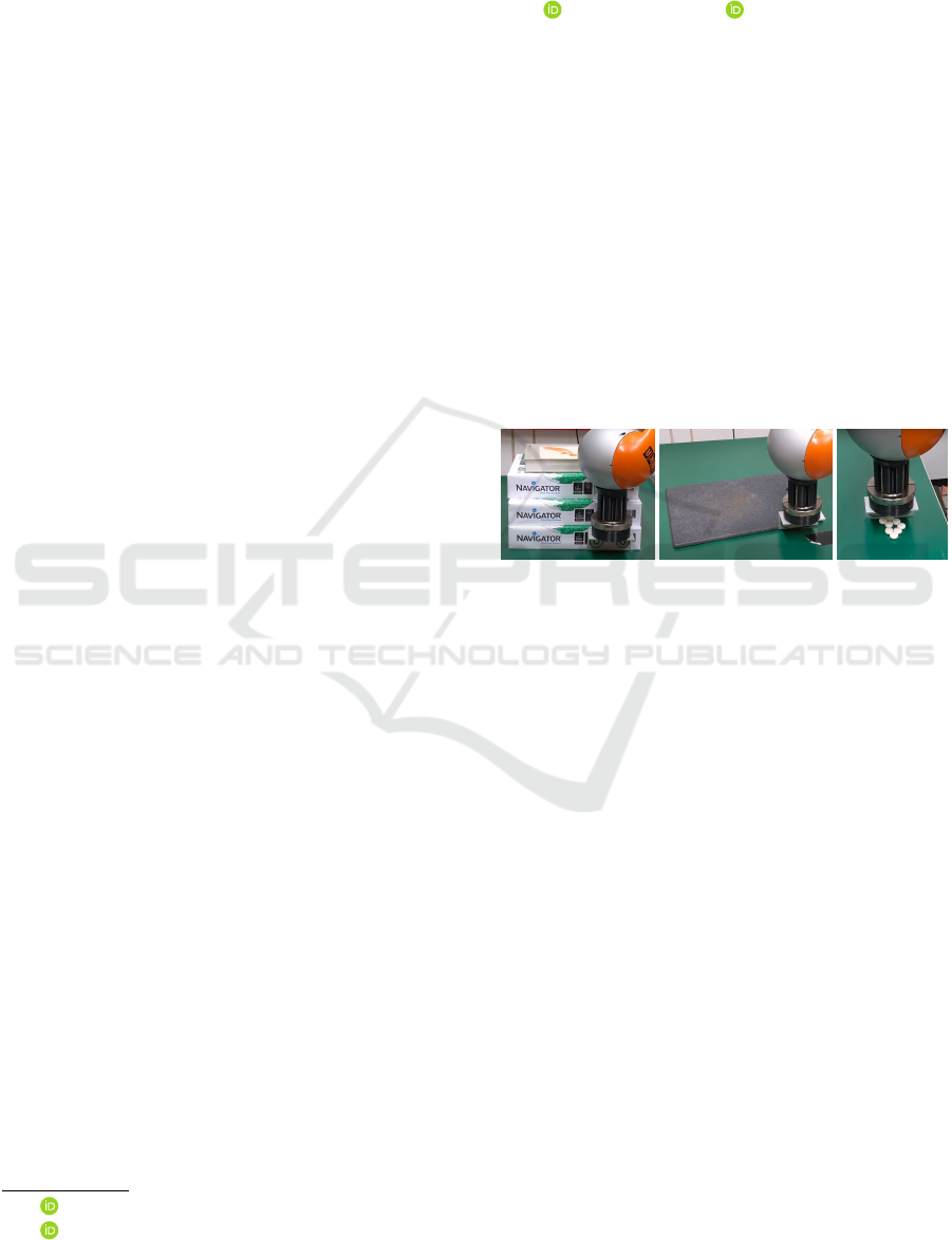
a specific gripper. Figure 1 shows the handling of dif-
ferent types of objects that are not easy to grasp due
to their geometric properties.
In addition to pushing objects from the side in
some cases applying a perpendicular force on an ob-
ject to move it around is better suited, for instance if
the object is very flat and lightweight, e.g., a sheet of
paper.
Humans exhibit advanced prediction capabilities
which enable estimation of the best action to be
taken to achieve the desired state, which means in-
verse model is assimilated by visual analysis, and/or
is learnt during execution based on action-effect
paradigm. Also, humans are capable of transferring
the learnt behavior to novel objects with different
physical properties (St
¨
uber et al., 2022). However,
a
https://orcid.org/0000-0002-3706-592X
b
https://orcid.org/0000-0002-6240-9181
Figure 1: Non-prehensile manipulation like pushing allows
robots to handle objects that are hard to grasp, e.g., heavy,
flat, or small objects.
pushing involves various uncertainties that robots
cannot predict which prevent them from delivering
similar pushing behavior. The main cause of this un-
certainty is the inadequate knowledge on frictional
forces which play significant role in pushing (Zhou
et al., 2016). Also, the pushing dynamics is highly
non-linear (Yu et al., 2016). While various proposed
approaches have delivered accurate forward models
for push-effect prediction, generalisation of the mod-
els to novel objects has still remained a challenge
(St
¨
uber et al., 2018; St
¨
uber et al., 2022).
Planning and controlling of various non-
prehensile motions such as pushing, rolling, throw-
ing, juggling have been explored in the literature
(Serra, 2016; Ryu et al., 2013; Lynch and Murphey,
2003). The survey in (Ruggiero et al., 2018) sum-
marizes the advancement in planning and control of
all these motions and provides an extensive literature
review. It further concludes that the growth in the
field of non-prehensile manipulation is relatively low
and human-inspired control strategies could provide
a potential solution to complex non-prehensile
manipulation tasks.
A comprehensive literature review is provided on
Bhat, P., Nieuwenhuisen, M. and Schulz, D.
Design and Implementation of Non-prehensile Manipulation Strategies.
DOI: 10.5220/0011320700003271
In Proceedings of the 19th International Conference on Informatics in Control, Automation and Robotics (ICINCO 2022), pages 67-78
ISBN: 978-989-758-585-2; ISSN: 2184-2809
Copyright
c
2022 by SCITEPRESS – Science and Technology Publications, Lda. All rights reserved
67

push manipulation in (St
¨
uber et al., 2022), consider-
ing it effective in various scenarios, for instance, with
uncertainty in the environment, and with need for pre-
grasp manipulation. In general, push manipulation
is used to maneuver objects from initial state to goal
state when the grasping of object is not feasible, e.g.,
due to object geometry. In addition, pushing is largely
used for pre-grasping to facilitate grasping of the ob-
ject, e.g., to create space in presence of clutter.
Directed standalone pushing is used in the liter-
ature vastly by mobile robots that are not equipped
with any manipulators. In (Krivic and Piater, 2018;
Krivic et al., 2016), objects are pushed with a sin-
gle contact towards a defined goal while learning the
properties of the object on the fly by observing their
behavior when pushed. In (Krivic et al., 2016), the
target object is expected to remain in a defined cor-
ridor, a region that is free of obstacles. The system
has to autonomously relocate when needed to exe-
cute pushing towards the defined goal. These works
mainly relax the assumption on knowing about the
key geometric properties of the objects to generalize
for novel objects, but apply basic single contact push-
ing due to the lack of manipulators. In (Li and Payan-
deh, 2007), two-agent point contact push is proposed
to allow more than one contact point using two agents
to push the target. This facilitates manipulation of
non-polygonal parts reducing position uncertainties.
Robot manipulators use pushing as an alternative
to grasping in various cases. In (Zito et al., 2012), two
level rapidly exploring random tree (RRT) planners
are designed, of which a global planner explores the
space of possible pushed object configurations and a
local push planner uses predictive models of pushing
interactions, to plan push sequences. A learning based
technique leverages differentiable physics simulator
to learn mechanical properties of the unknown object
to push it from initial to goal configuration in (Song
and Boularias, 2020). The method computes gradient
distance between predicted and actual poses and uses
the gradient to identify the mechanical properties.
When an object is located in a clutter, pushing is
performed around the target object to achieve gras-
pablity. While in (Dogar and Srinivasa, 2010), the
target object is pushed away and grasped, in (Zeng
et al., 2018; Dogar and Srinivasa, 2011; Cosgun et al.,
2011), the surrounding objects are pushed. The sur-
rounding objects are pushed to create space to place
target object on a cluttered surface in (Cosgun et al.,
2011). It is important to note that in push-grasp lit-
erature, the planning is mostly in the higher level to
generate a sequence of pushes that is required enable
the manipulation of target object. As the goal state of
the surrounding objects are the not the primary con-
cern in these cases, controlled pushes are not applied
on the objects.
The application of pushing as pre-grasp manipu-
lation is not exclusive for cluttered environments, but
is integrated in the manipulation strategies in a hand-
ful of grasp planners. A human-inspired grasping
framework is proposed in (Sarantopoulos and Doul-
geri, 2018) to grasp domestic flat objects, which uses
pushing/sliding to bring the object to the edge of the
table surface to eventually grasp it with one of the
proposed strategies. In (Eppner and Brock, 2015), the
aim is to utilize environmental constraints to grasp the
objects, and the objects are pushed to achieve config-
uration such that they can be grasped with the sup-
port of external contacts. However, the pushes used
in these approaches are constrained by position and
geometric properties of the objects. For example,
the strategy proposed in (Sarantopoulos and Doulgeri,
2018) cannot slide the objects that are far from the
edge of the table surface. In (Omr
ˇ
cen et al., 2009), a
learning-based approach is proposed to enable push-
ing of target object to new location from where it
can be grasped easily. The idea is to allow a robot
learn general pushing rule defining the relationship
between the direction of push and the resulting object
motion for a set of objects.
Although pushing is widely used to manipulate
objects, it suffers from prediction and state uncertain-
ties (St
¨
uber et al., 2022). Planning and control of
pushing motion is hence challenging when a hard goal
constraint is imposed as inverse model is not avail-
able to predict the action to be taken to achieve the
desirable state. The problem becomes more complex
with varying geometric shapes and sizes of the tar-
get object. Majority of the approaches investigated in
(St
¨
uber et al., 2022) assume that the geometric prop-
erties of the target objects to be known. This assump-
tion does not bridge the gap between the dexterity of
humans and robots in non-prehensile manipulation.
2 SYSTEM DESIGN
The analysis provided in the previous section high-
lights the dissimilarities in the human and robot push
manipulation which mainly includes the difference in
the push contact configuration and lack of knowledge
on the push-effects due to unavailable object dynam-
ics. In this work, the important constituents of push
manipulation are recognised and designed to provide
a human-inspired solution. The aim is to deliver a
design solution that provides push manipulation of a
vast set of objects with varying geometric properties.
ICINCO 2022 - 19th International Conference on Informatics in Control, Automation and Robotics
68
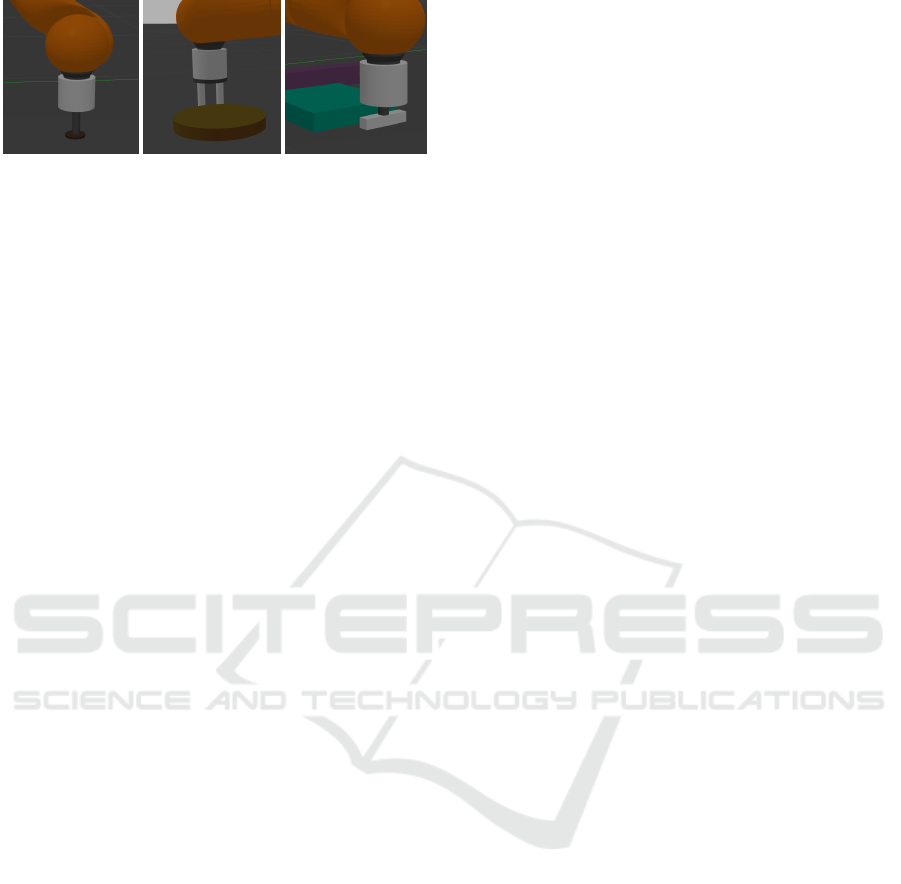
Figure 2: Endeffector configurations for pushing. Left: Sin-
gle point contact. Center: Multi-point contact. Right: Line
contact.
2.1 Gripper Configurations
Humans tend to relax high-level control by exploit-
ing available finger configurations while handling a
diverse set of objects. However, robots mostly use
a single point contact for push applications relying
on complex control for task execution. While single
point contact is easy to establish with a simple rigid
finger or no gripper, a dexterous gripper attachment
providing features of human hand is not a cost effec-
tive solution. To compensate for the trade-off, in this
work, simple human-inspired gripper configurations
are proposed: single-point contact, multi-point con-
tacts, line contact.
Each of these grippers are designed considering
hand positioning tendency in humans with varying
geometric properties of the objects. With a dexter-
ous gripper possessing at least two single-joint fin-
gers, all the configurations can be generated with the
same gripper. However, in this work, different gripper
attachments are designed. Figure 2 depicts the three
realized gripper configurations.
Single Point Contact. Gripper configuration pro-
viding single point contact allows the manipulator to
apply force on the object at a single point. In the push
manipulation literature, single point contact is usu-
ally established such that the applied pushing force
lies horizontal to the support plane while gravity acts
along the vertical direction. However, applying ver-
tical force on the object constrains the sliding of the
object due to high pushing force. With this configura-
tion, small objects such as a bottle cap can be manip-
ulated.
Multi-point Contact. A two-point contact is shown
to deliver a more stable push compared to a single
point contact in (Lynch, 1996). This configuration
can be useful when achieving more stable control over
the objects is required, for instance, when they are
relatively flat and deformable, e.g. files, cards. This
gripper configuration also finds application in manip-
ulating taller objects with convex/concave surfaces.
Line Contact. When objects are too heavy and/or
big, prehensile manipulation can be restricted by grip-
per design. When the target object is a heavy book or
a box, pushing it from the side while almost wrapping
one or more fingers around the object can be an alter-
nate solution. Also, humans use such pushing strat-
egy to handle odd shaped objects or multiple objects
at once.
With the proposed human-inspired design of grip-
per configurations, this work aims to handle a di-
verse set of objects with non-prehensile approach us-
ing simple control strategies.
2.2 Control
Humans depend on their natural haptic and force
feedback to control contact forces. Similarly, the con-
tact force between a robot and its environment should
often be monitored to ensure successful execution of
tasks which requires the robot to interact with its envi-
ronment. The control interfaces that enable such com-
pliant behavior are discussed in this section.
Further, various control strategies designed to
compensate for the lack of dexterity and haptic feed-
back in human hands are explained. The control
strategies coupled with gripper design aims to prevent
undesirable effects in the motion of the target objects
as opposed to previously discussed learning based ap-
proaches that learn to predict the effects of pushes for
push manipulation.
When a robot has to push the target object, a per-
pendicular external force is exerted on the support
surface even before any force is applied on the ob-
ject. The force between a gripper and a surface has
to avoid any damage to the robot and its environment.
Further, the applied force by a robot to push the target
object plays an important role in the execution of push
manipulation. Hence, it is necessary to control push
force to avoid sliding of the objects away from robot
gripper. This section discusses different robot control
modes that can be used to obtain desirable interaction.
Open-loop Motion Control with Force-torque Sen-
sor. To use pure motion control for the tasks involv-
ing contact between a robot manipulator and the en-
vironment, an accurate model of the environment is
required (Siciliano et al., 2000). As a precise model
of the environment is difficult to obtain, pure motion
control easily fails to handle such tasks. If the accu-
rate position of the table with respect to robot is not
known, the robot fails to establish contact with the ta-
ble. In worst case, if the table resists the robot from
reaching its commanded position, the robot may dam-
age the table and/or itself.
Design and Implementation of Non-prehensile Manipulation Strategies
69

Hence, it is important to detect contact between
the robot and the environment. To achieve this, a
force/torque sensor can be mounted on the manipu-
lator to sense the physical interactions (Alex Owen-
Hill, 2021).
Impedance Control. Impedance control is a widely
used method to obtain compliant behavior in robots
(Schindlbeck and Haddadin, 2015; Ott et al., 2010).
It defines the change in endpoint motion as a function
of disturbance forces. It demands robots to deliver a
definite mass, spring, and damper properties.
The goal of impedance control is to achieve the
behavior
M ¨x + D ˙x + Kx = F
external
(1)
where M, D and K are positive virtual mass, damping
and stiffness matrices, x ∈ R
n
is the task-space config-
uration and F
external
is the applied external force and
(x, ˙x) is the current state.
The impedance controller senses the endpoint
motion x(t) and maps the change in endpoint mo-
tion to appropriate end-effector force −F
external
by
commanding joint torques using an inverse dynam-
ics model. To get a more precise interaction force
−F
external
, a force-torque sensor providing a feed-
back term can be added at the end-effector (Lynch
and Park, 2017). In addition to impedance control
that is realised via software, compliance can also be
achieved with passive impedance control by manu-
ally adjusting mechanical impedance of the robot with
flexible joints and/or links (Vukcevic, 2020). In addi-
tion, a compliant mechanical device can be interposed
between robot end-effector and environment to ensure
a compliant behavior with passive impedance control.
Both active and passive impedance control can also be
combined to achieve an effective compliant behavior
(Schindlbeck and Haddadin, 2015).
Admittance Control. When executing non-
prehensile tasks such as pushing, the robot should
offer a compliant behavior to provide a controlled
pushing force in the desired directions. To induce
compliant behavior, an external admittance control
loop can be provided to the motion-controlled robot
(Al-Jarrah and Zheng, 1998). Admittance control
maps external force to end-effector acceleration. The
external force applied is measured using a load cell
or a force-torque sensor (Lynch and Park, 2017).
The approach is to calculate the desired end-
effector acceleration
¨x
desired
= M
−1
(F
external
− D ˙x − Kx) (2)
where M, D and K are positive virtual mass, damping
and stiffness matrices, x ∈ R
n
is the task-space config-
uration and F
external
is the applied external force and
(x, ˙x) is the current state. The commanded joint forces
and joint torques τ
cmd
can be calculated using inverse
dynamics (Lynch and Park, 2017).
2.3 Control Strategies
Compliant control strategies are needed along with
well-designed grippers to provide a robust control to
perform better in unideal situations. The underlying
objective is to not lose contact with the pushed object.
While a visual feedback can also be utilised to locate
the pushed objects and re-establish contact if the ob-
jects slide away, in this case, only force feedback is
taken into account to monitor physical interactions.
To maintain contact with the target object while
applying a suitable force on the target object to induce
desirable motion, a 1-DOF admittance control policy
is used to map the force/torque measured to push ve-
locities such that,
D ¨x = F
external
(3)
from equation 2.
Alignment of Gripper along Object Surface.
When a robot gripper is not well aligned along the
surface of the target object, the contact between grip-
per and the target object can be broken easily. Con-
sider the example gripper-object configuration from
top-view shown in figure 3 (left) where “O” is a tar-
get object and “G” is a line contact gripper. The line
gripper here is not perfectly aligned along the surface
of the object. When the robot continues to push the
object in this configuration, the object tends to ro-
tate and eventually loses contact with the gripper as
shown in figure 3 (center). Hence, it is necessary to
align the gripper along the object surface to avoid the
undesirable rotation of object. The torque produced
at the center of the gripper along perpendicular direc-
tion due to the existing force between the object and
the corner of the gripper can be mapped to a linear
velocity along the surface of the gripper given by,
v
y
= −k
y
τ
z
(4)
where v
y
is the velocity along the surface of the ob-
ject, τ
z
is a non-zero torque at the center of the grip-
per about z-axis and k
y
is the proportional gain. This
allows gripper to move to the center of the object and
achieve a desirable configuration as shown in figure
3 (right) where torque τ
z
= 0. However, it is neces-
sary to choose a suitable proportional gain to obtain a
smooth alignment without oscillations.
ICINCO 2022 - 19th International Conference on Informatics in Control, Automation and Robotics
70

Figure 3: Effects of alignment of an endeffector (G) with an
object (O) based on torque (τ
z
).
Regulation of Push Velocity during Alignment.
To allow smooth pushing motion, it is necessary to
control push velocity such that the velocity along
push direction, for example, v
x
in figure 3 is maxi-
mum when alignment velocity v
y
= 0 which means
the torque τ
z
= 0 and is minimum when the torque
and alignment velocities are high. The behavior can
be achieved by mapping the torque τ
z
to push velocity
v
x
.
Emulation of Curved Gripper. Humans tend to
form a curved configuration, especially when small
multiple objects are to be pushed, to keep the objects
integrated. This could be resembled by a curved grip-
per design. An alternate solution could be provided
to induce the feature of curved gripper configuration
in a line gripper by inducing timed oscillations into it
as shown in figure 4. The cyclic angular motions are
commanded here about z-axis to produce oscillations
at a definite frequency rate. This enforces pushing of
objects from either sides of the gripper to the center
to keep objects integrated. Additionally, the torque
induced about z-axis from the target object at the cor-
ner or at the off-center of the gripper can be mapped
into angular velocity providing a closed loop control
given by,
ω
z
= k
z
τ
z
(5)
where ω
z
is the angular velocity about z-axis, τ
z
the
measured torque, and k
z
is a proportional gain. In this
case, oscillations do not occur at constant rate but,
angular motions depend on the torque generated by
the virtue of the position of the target object. When
the object/s are at the center of the gripper, no angu-
lar motions are generated. This case demonstrates the
role played by the design of gripper in simplification
of control strategy. If a curved gripper is used over a
simple line gripper, the design of the gripper compen-
sates for the control. A simple gripper however relies
more on the control strategy.
2.4 Software Architecture
In order to provide a suitable software design pattern
for the execution of actions in a pre-defined sequence,
a state machine is implemented such that each state
Figure 4: Comparison of curved gripper and oscillated line
gripper configurations.
Figure 5: An action sequence for a push manipulation task.
in the state machine corresponds to an atomic action
that can be invoked from the action sequence. The ac-
tion states command velocities to actuate the desired
actions and end of each action is marked by a sub-
goal encoded into the states. Each state is independent
of each other, providing a flexible arrangement of ac-
tions in the action sequence. Our actions are: Reach:
In this phase the robot end-effector moves towards the
target object and lands behind the object surface in the
pushing direction on the support surface. The goal
is to form contact with support surface and not with
the object surface. The phase ends when robot forms
contact with the support plane. Translate: The robot
is expected to form contact with object in this phase.
It translates towards the object while in contact with
the support plane. The end of the phase is signified
by the contact event between robot gripper and object
surface. At the end of this phase, the gripper is in con-
tact with both object and support plane. Push: While
pushing is a an atomic action by itself, the action can
be decomposed and organised in a way to avoid con-
tinuous pushing for more flexibility. For instance, the
robot can be commanded additional actions to raise
and reorient to disconnect and reconnect contacts to
provide more possible actions. Such discretisation al-
lows robot to change the orientations and directions
of push with no constraint of pushing in a continuous
trajectory. When the object reaches pre-defined goal
location, the phase is ended. Disconnect: All the con-
tacts can be detached once the goal is reached and the
robot can return to its “home” position. The reorient
and raise actions can also be utilised for the purpose.
Figure 5 shows an action sequence with four
action-phases with different atomic actions.
Design and Implementation of Non-prehensile Manipulation Strategies
71
3 EVALUATION
We conducted experiments both, in simulation and on
a 7-DoF KUKA LWR 4+ robot arm.
The real robot arm provides torque measurements
for each of its joints and an estimated external Carte-
sian force and Cartesian torque acting on the endef-
fector. However, the torque estimate is not reliable,
as in our scenarios forces applied to different posi-
tions of the endeffector yield a large torque at the first
robot joint due to the long lever. Thus, as our endef-
fector axis is perpendicular to the surface, we use the
torque measured at the endeffector joint in this work
along with the estimated external force to obtain a bet-
ter estimate.
An interface between external computer and
KUKA Robot Controller (KRC) can be established
using Fast Research Interface (FRI) library provided
by KUKA. The FRI library can be used to command
robot in joint position, joint impedance and carte-
sian impedance control modes. A library extending a
higher level interface over the original FRI communi-
cation protocol is provided by the Stanford Artificial
Intelligence Laboratory.
In this work, Robot Operating System (ROS) in-
terface developed by the Research Center E. Piaggio
1
is used to provide realization in a standard, agile con-
trol framework. Also, the ROS interface enables nec-
essary tools for robot simulation and visualisation.
The ROS package for KUKA LWR
1
provides final
interfaces with KUKA FRI, Stanford FRI library and
also includes Gazebo simulation plugin.
3.1 Pushing with KUKA LWR4+ Robot
The experiments were conducted with a stack of pa-
per bundles and a book, and a cutting board which is
comparatively lighter, depicted in figure 1. In these
cases, a line gripper can be seen pushing the objects
from a side surface. As the gripper is not aligned at
the center of the surface of the objects, the measured
torque (about z-axis in this case) is then mapped to
the linear velocity along the surface of the object (ve-
locity in x-axis) to provide a better alignment. The
line gripper has a push contact with a board with a
stack of objects at one of its corners. If the contact is
established perfectly at the center of the gripper, ide-
ally, no torque is produced. However, if unaligned,
a high torque can be observed depending on the dis-
tance between the point of contact and the center of
the gripper and on the mass of the object/s.
The commanded velocities and the measured
torque in push manipulation executed with the above
1
https://github.com/CentroEPiaggio/kuka-lwr
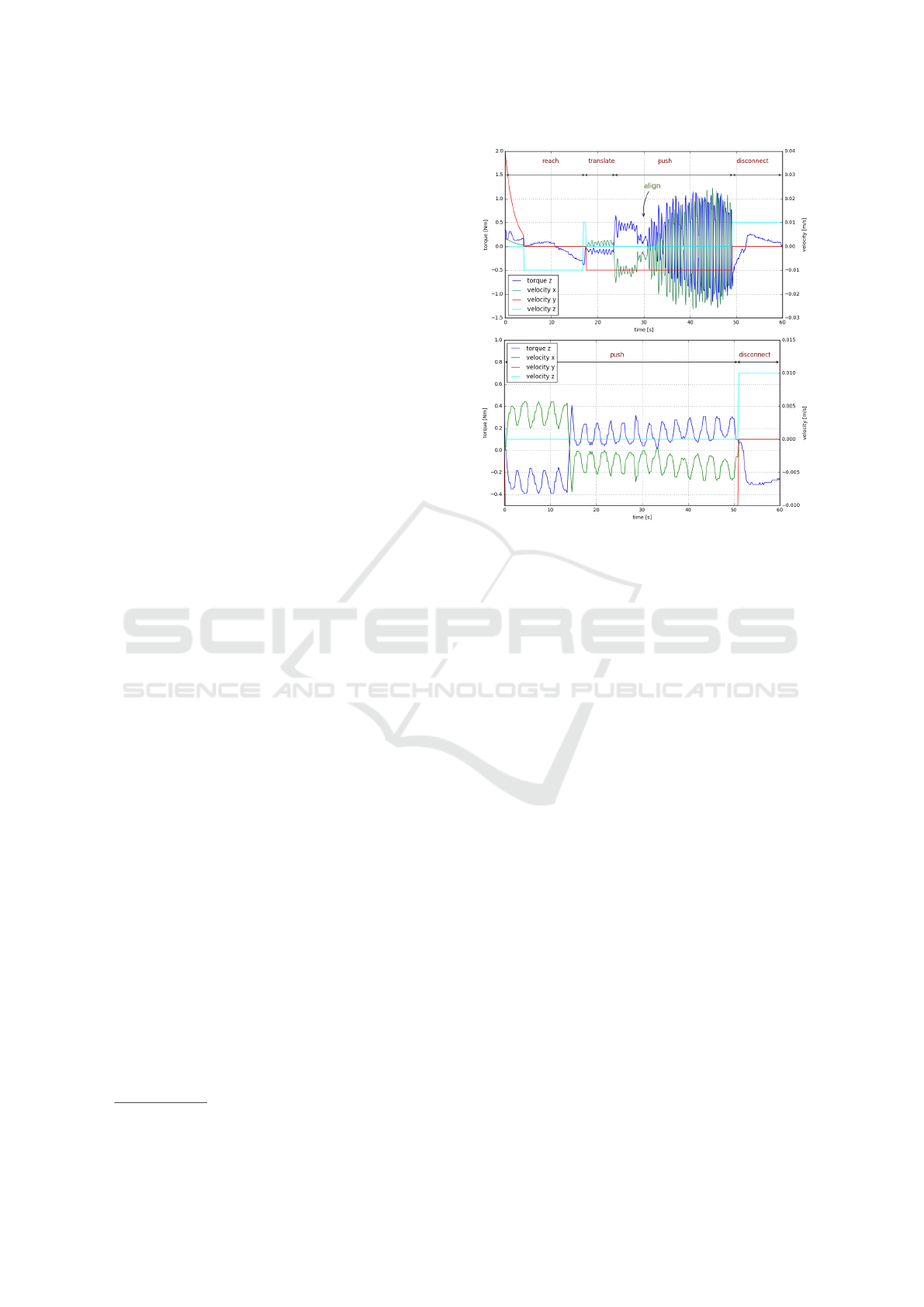
Figure 6: Torque measurements from push manipulation of
a set of objects with different geometric properties and ori-
entations in a real world scenario (depicted in figure 1). Top:
Stack of paper bundles. Bottom: Cutting board.
mentioned cases are shown in figure 6. As in all
the considered cases, the torque produced has to def-
initely reflect in the torque measurements in z-axis, it
is taken into consideration for evaluation. The torque
measurement from the push manipulation of the stack
of paper bundle and a book is shown in the top graph.
In the reach phase, the robot moves down towards the
object and touches the support surface. The velocity
is commanded in z-axis to achieve this motion. Ide-
ally, the torque should be zero, as there is no force
acting on the gripper. However, some torque can be
observed in the reach phase due to noise in the sensor
readings. A small upward movement is commanded
during experiment after the robot makes contact with
the support surface so as to avoid scratching of the
surface by the gripper. A peak in the velocity in z-
axis signifies this movement.
An online sensor calibration is performed after the
contact with the surface. In the translate phase, a
small torque can be observed. A sharp increase in
the torque value is due to the contact established with
the target object. The torque is mapped to linear ve-
locity which causes the velocity in x-axis to exhibit
a negative correlation with the torque values. At the
point of alignment, at approximately 30 seconds, the
torque and velocity drop indicating a good alignment
with the object. Although line gripper is aligned at
the center, the oscillations can be observed as the sys-
tem is under-damped. The torque values drop again
ICINCO 2022 - 19th International Conference on Informatics in Control, Automation and Robotics
72

when the contact is disconnected by moving the grip-
per away from the object and the support surface.
When a push manipulation is executed with the
similar order of actions for a board which is compar-
atively much lighter than the stack of paper bundle,
a very small torque (maximum 0.2 Nm) is measured.
The alignment velocity in x-axis is also consequently
small, hence producing an average alignment during
pushing. Although robot managed to align approxi-
mately at the center of the board during experiment,
it is hard to interpret the point of occurrence of align-
ment unlike in the case of paper bundle stack.
When line gripper makes a contact at the corner of
the board, the contact does not lie exactly at the cen-
ter of the gripper, which induces considerably high
torque due to the high mass of a paper bundle and a
book stacked on the board. This causes the controller
to react and produce an alignment velocity which
causes motion of the robot to align to the center. In
this case, the board slid slightly to the other off-center
when the robot tried to align causing a sharp change
in the direction of torque at around 15 seconds. The
board then remained in the same contact configuration
which is indicated by a non-zero torque in the graph.
The push phase is ended when the robot disconnects
from the object and the support surface.
3.2 Pushing in Simulation
We use the gazebo plugin provided in the KUKA
LWR ROS package to control the robot in simula-
tion. As the joint torque measurements in simulation
are not accurate as the commanded torques are not
taken into account while computing estimated exter-
nal torques, we employ a force-torque-sensor plugin
to obtain wrench measurements at the endeffector, in
contrast to the real robot setup.
The experiments conducted to evaluate the perfor-
mance of the force/torque sensor plugin in simulation
is similar to that of the real robot platform. As in the
case of real robot, the push manipulation is executed
on various objects that differ in size, shape and mass.
In addition, the corner-to-surface contact configura-
tion between the gripper and the target object is also
considered for the experimentation.
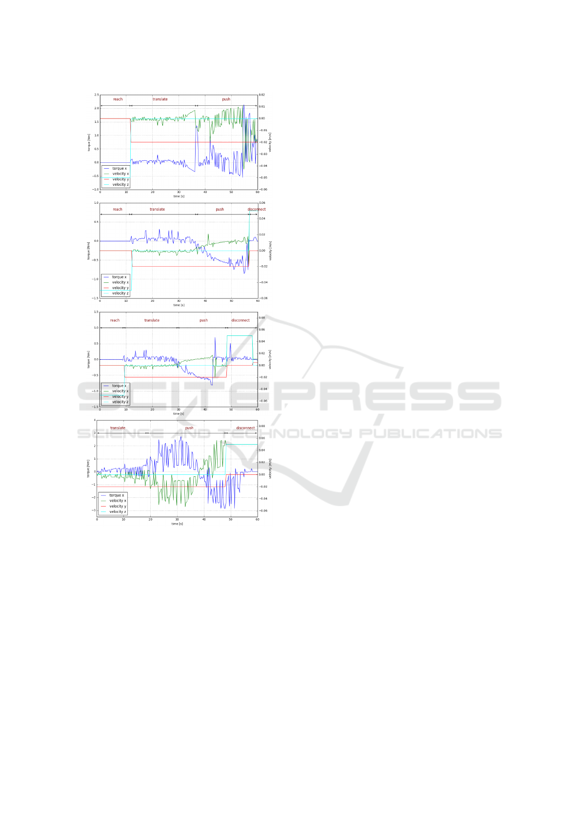
The simulated objects to push are a) a heavy block
(2kg), b) a slab (200g), c) a disc (100g), and d) a block
(1kg). In the first two cases (a and b) the gripper
establishes an even contact on a side surface of the
target object. Even though the objects heavy block
and slabs are comparable in shape, they vary in mass.
The line gripper establishes a centered contact with
the curved curved surface of the disc (c). The block
(d) is aproached fat one of its corners. The results are
depicted in figure 7.
The measured force/torque values are in the sensor
co-ordinate frame in simulation. Hence, the torque
due to push manipulation in the experiments in re-
flected in torque about x-axis. For the heavy block
(a), in the reach phase the robot moves down with ve-
locity commanded in the z direction. In this phase, no
external force is acting on the robot end-effector and
the measured torque is zero, thus providing an ideal
measurement as opposed to real robot sensors which
usually possess some noise. In the translate phase,
a small torque can be observed due to contact with
the support surface. The sudden increase in torque
signifies the established contact with the target object
approximately at 36 seconds. The robot continues to
push the object while aligning along the surface of the
object which is represented by the oscillating torque
and velocity values in x direction.
When the slab (b) with comparably low mass is
pushed, a very small torque is induced. The reach
and translate phases are however comparable to the
corresponding phases in the case of heavy block in
terms of torque measurements. The robot in this case
is able to align along the surface but does not behave
as good as with a heavy object. The results from
these two experiments are comparable to the first two
experiments on a real robot with the stack of paper
bundle and a board. The push manipulation of the
light weighted disc (c) also exhibits similar behavior
as with the slab. The curved surface however adds an
additional challenge in pushing which causes the line
contact gripper to barely maintain a contact with the
disc. During pushing, the disc moves off-center and
eventually loses contact with the gripper at approxi-
mately 45 seconds.
In the configuration where the contact is estab-
lished by the gripper at a corner of the block (d), the
torque values are considerably higher than zero in the
translate phase as the corner is not perfectly at the
center. The motion induced by alignment velocity in
x direction causes the object to slide along the surface
of the gripper in a “to and fro” fashion. This behavior
is captured in a roughly periodic curve.
3.3 Gripper Configurations
The three different gripper configuration designs de-
scribed in this work are evaluated on a different set of
objects. Each gripper configuration is designed with
a purpose so as to collectively provide pushing of ob-
jects with various geometric properties. In the con-
ducted experiments, the objects are chosen for each
gripper with an aim to corroborate their relevance and
identify their limitations.
Design and Implementation of Non-prehensile Manipulation Strategies
73
a)
b)
c)
d)
Figure 7: Torque measurements from push manipulation in
simulation environment. a) Heavy block. b) Slab. c) Disc.
d) Block.
Single Point Configuration. To set up a single
point gripper configuration, a sponge block is at-
tached to the manipulator as shown in figure 8. This
also serves as a source for passive compliance when a
contact is established with the environment. Although
the sponge attachment mostly delivers a higher sur-
face contact for a “point” contact, the point contact is
only relative to the geometry of the target object.
In this experiment, the single point contact is used
to manipulate a set of objects possessing various ge-
ometric properties. A set of flat and deformable (tis-
sue), flat and wide (board), small (box), tall and light
(cylinder), flat and heavy (paper bundle) objects are
manipulated as shown in figure 8. The robot is ex-
pected to establish a contact on the top surface of the
object and push it to a defined location while clamp-
ing the object against its support surface. The robot
moves down until it reaches the surface of the ob-
ject constituting a reach phase. The increase in force
due to contact triggers the push action to form a push
phase.
The robot manipulator is able to squeeze and push
most of the considered objects, however, the config-
uration fails to handle the heavy objects. In the case
of the board, the object is wide which makes it ro-
tate about the contact point during pushing. But, the
robot is able to push the board to a desired location.
However, with increase in the weight of the object,
the single point contact starts to fail as it slips off the
surface of the object.
This behavior is reflected in the measured force
values during task execution as shown in figure 9. The
velocity commands in z and y directions are reach and
push velocities respectively. The negative velocity in
the reach phase causes the robot to move down to-
wards the object. A high force is measured when the
robot touches the surface of the object. The estab-
lished contact switches the action from push to trans-
late where the push velocity is commanded in y direc-
tion.
In the case of a successful push of the objects,
the force in z-axis which corresponds to force due
to contact between object surface and the gripper, is
linearly increasing in the translate phase. The force
is constrained to 5N in this direction. The existence
of force in z direction shows that a clamping force is
applied on the top of the object. The comparatively
higher force measured in y-axis is also increasing lin-
early and it also increases with the mass of the ob-
ject. The maximum force measured with tissue and
small plastic box is around 10N and with object with
higher mass, the force exceeds 15N. The sheer force
in the sponge attachment could be a source of mea-
sured force in both the directions.
The robot as mentioned earlier, fails to move the
heavy paper bundle. After the contact is made with
the object, the robot tries to push the object in the y
direction. However, when the object fails to move, the
gripper slips and moves away from the object. The re-
gion where the slippage occurs is marked in the figure
9. The trough in the graph at around 35 seconds can
be interpreted as a shift from static friction to dynamic
friction occurring due to the resistance offered to the
motion by the surface of the paper bundle during the
slip. The robot slightly moves down due to force in z
direction after it slips off the object surface.
ICINCO 2022 - 19th International Conference on Informatics in Control, Automation and Robotics
74
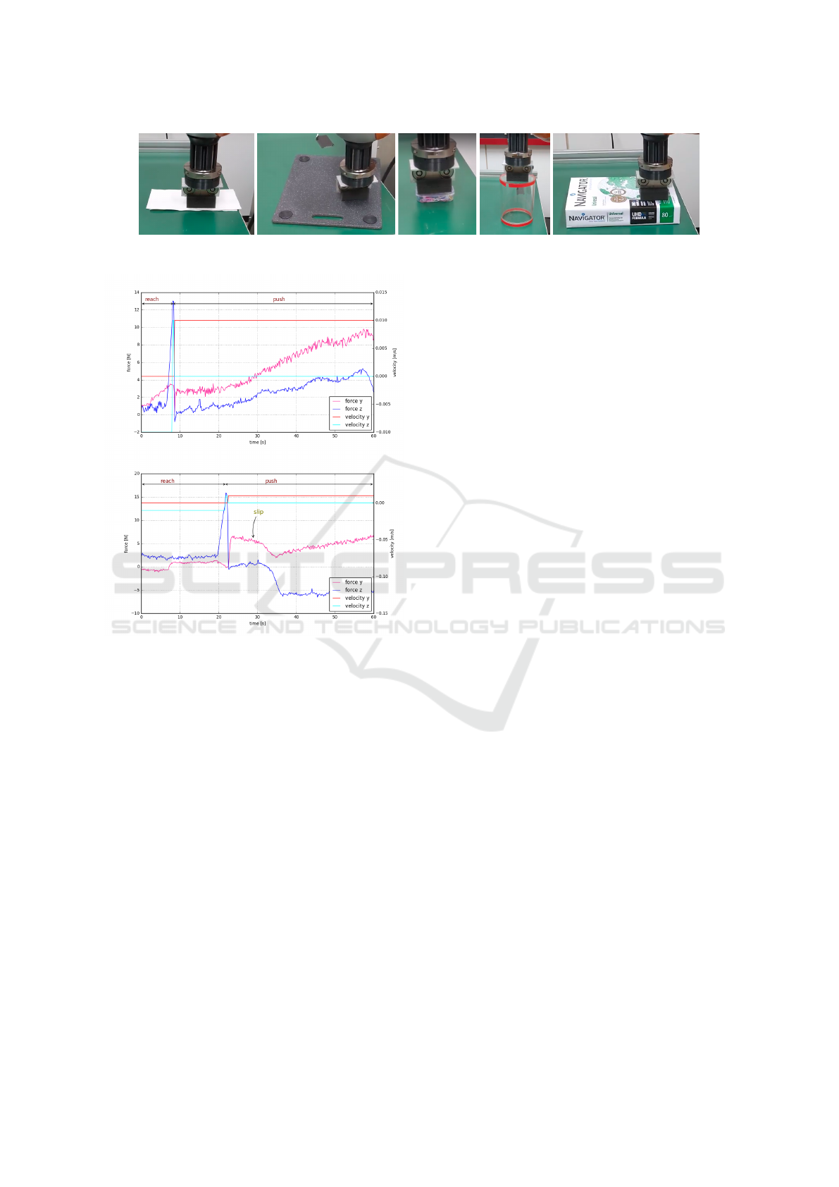
Figure 8: Single point configuration for different objects: a) Tissue. b) Board. c) Small box. d) Hollow cylinder. e) Paper
bundle.
Figure 9: Force measurements from push manipulation of a
set of objects with single point gripper configuration. Top:
Tissue. Bottom: Paper bundle.
With the considered set of objects, the gripper
configuration achieves successful push in the case of
light objects irrespective of the geometry as long as it
is possible to make a contact at the top surface. How-
ever, the gripper configuration does not deliver good
results for a wide and/or a heavy object.
Line Configuration. A line gripper configuration
provides a high surface area to establish contact with
a target object, hence providing a greater grip to ma-
nipulate heavy and/or large objects. Also, the high
surface area can be useful in pushing multiple small
objects such as a pile of screws.
In this experiment, a heavy object, i.e., a bundle of
paper is placed on a board to induce more friction in
the setup. The line gripper is able to push the heavy
object by aligning with a surface of the object. While
the gripper can push the object when it is almost at
the center of the object, pushing with a bad alignment
often causes the object to rotate, eventually losing the
contact with the object. In this case, an alignment
strategy is used to map the measured torque to linear
velocity to align the gripper with the surface of the ob-
ject. The gripper is able to push the object, even when
the mass is increased by adding an another bundle of
paper.
In the graphs shown in figure 10, commanded ve-
locities and the measured torque provide an overview
of the experiment with two paper bundles. In the
reach phase, the commanded velocity is in z axis to
move the robot towards the object in the downward
direction. The robot touches the support surface at
around 20 seconds which causes peak in the torque
values. The next defined action translate is hence trig-
gered, causing the robot to move towards the object
while in contact with the support surface. The com-
manded velocity in y direction is used for this action.
The translation is ended when the robot touches the
object, which causes the torque value to increase fur-
ther. The velocity in x which corresponds alignment
velocity along the surface of the object. The gripper
aligns and pushes the object in push phase and finally
disconnects by moving up when desired location is
reached. A similar behavior was observed with re-
duced mass of the single paper bundle. The line grip-
per can easily handle the target objects when a full
surface-to-surface contact is established and can serve
the purpose of the design to handle heavy objects.
When line gripper is used to push objects with no
even surface, for example, curved or concave objects,
the design of the line gripper cannot be exploited. For
instance in an experiment with a tape roll the line grip-
per contact is comparable to a point contact push. Al-
though a combination of low push velocity and a good
force/torque sensor can enable the line gripper to push
the curved surface objects, it does not always deliver
a good result.
Multi-point Configuration. A multi-point gripper
is comparable to line gripper when it is aligned along
a even surface of an object. It provides a contact at
two points on an even surface, providing the same sta-
bility as a line gripper. The feature of the design that
surpasses the design of the line gripper configuration
Design and Implementation of Non-prehensile Manipulation Strategies
75
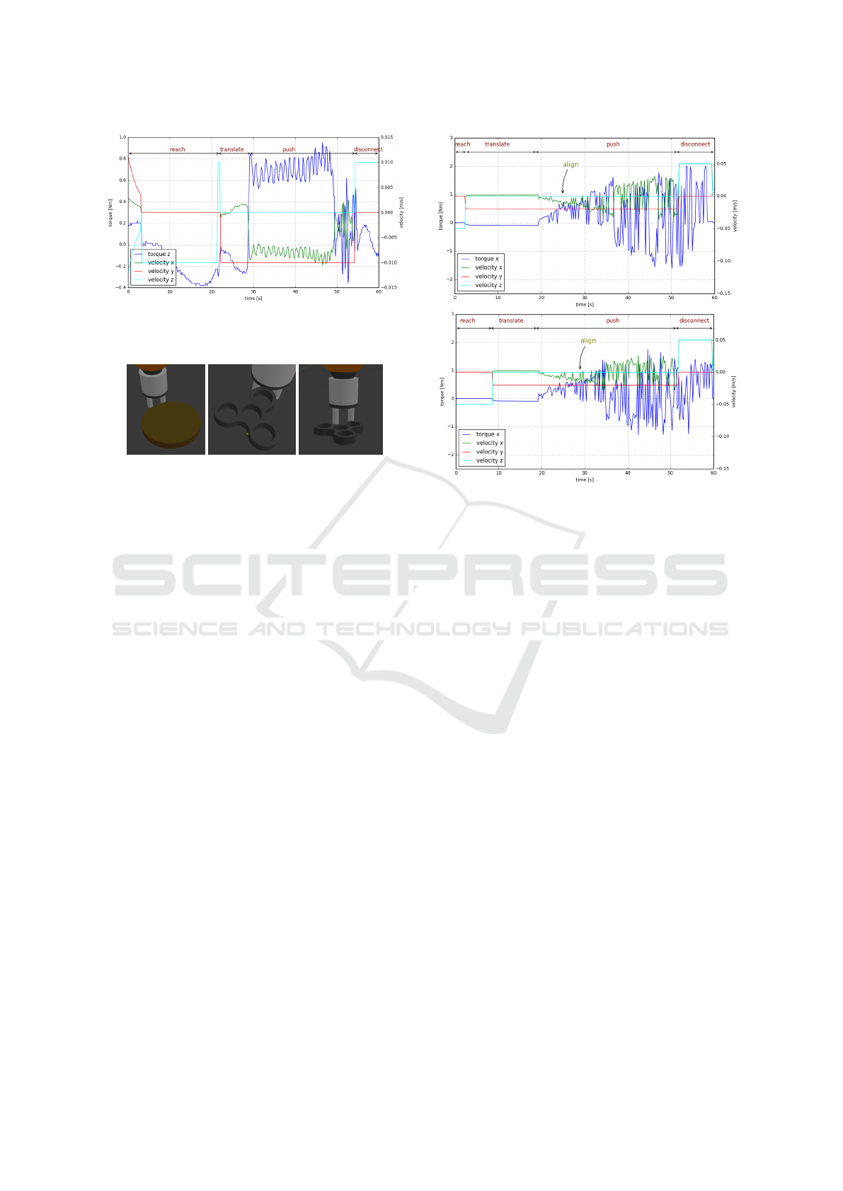
Figure 10: Commanded velocities and measured torques for
push manipulation using line configuration. Two paper bun-
dles on a board pushed using line configuration.
Figure 11: Multi-point configuration for different objects:
a) Disc. b) Fidget spinner, convex contact surface and c)
concave contact surface.
is its ability to firmly handle objects with curved and
concave surfaces. A two-point gripper can be seen es-
tablishing two contacts with a disc and a fidget spin-
ner in figure 11.
The push manipulation executed with the disc and
the fidget spinner (aligning with the curve surface) in
simulation and the gripper configuration was able to
push both the objects to the desired location. The
graphs in figure 12 show the commanded velocities
and the measured torque values during execution, rep-
resenting the states involved. The torque is measured
by a force-torque sensor plugin in the simulation and
the measurement shown in the graph is in the sensor
co-ordinate system. In the reach phase, velocity is
commanded in z-axis to move the robot in downward
direction. The establishment of contact invokes the
translate phase marked by a non-zero velocity com-
mand in y-axis.
In both cases, a single point contact is formed ini-
tially as the object is not centered with the axis of the
multi-point gripper. Hence, a sudden change in the di-
rection can be seen in the torque, and consequently in
the velocity in x-axis, signifying the alignment with
the surface by mapping generated torque to velocity.
Further, the robot continues to push the target object
in the push phase and finally disconnects when the
target location is reached by moving up in z direction.
Although the multi-point configuration achieves
the push manipulation task in this experiment, the
success also depends on the distance between the two
fingers of the gripper and the size of the object.
Figure 12: Commanded velocities and measured torques
for push manipulation using multi-point configuration. Top:
Disc. Bottom: Fidget spinner.
3.4 Control Strategies
Open Loop Control. To investigate the cases where
the open loop control fails to handle the geometric
properties and/or the orientations of the target ob-
jects, experiments are conducted in both simulation
and real-world environment on different set of objects
and push contact configurations.
We evaluate different contact situations with the
line gripper and a stack of paper bundles on a cutting
board: a) the line gripper is in contact near the edge
of the board such that only half of the gripper surface
forms contact with the board surface, b) the object
stack is disoriented with respect to the gripper surface
and c) the gripper makes contact with it away from the
center and near the center respectively. In the first two
cases, the gripper loses contact with the stack during
pushing as it begins to rotate. However, in the third
case, the gripper is able to keep the contact intact as
the stack is only slightly rotated and hence tends to
align passively with the gripper while rotating.
The experiments with open-loop control are also
conducted in simulation environment with a similar
and an additional case. The objects used for push
manipulation are a) a slightly disoriented block (1kg)
which makes an off-center contact with the gripper
and b) a pile of buttons (5g each) lying away from
center of the gripper. The objects are pushed using an
open loop control.
ICINCO 2022 - 19th International Conference on Informatics in Control, Automation and Robotics
76
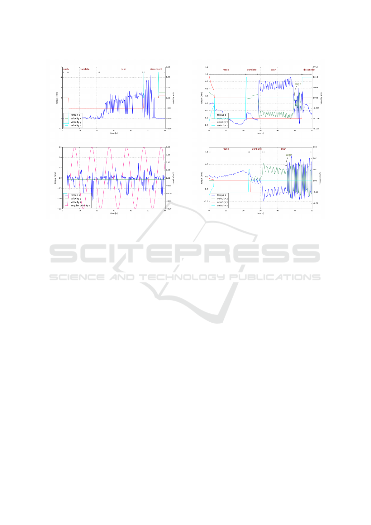
Figure 13: Commanded velocities and measured torques for
different push contact configurations using open loop con-
trol. Top: Line gripper pushing at a contact away from the
center of a slightly tilted block. Bottom: Line gripper in-
duced with oscillations to handle a pile of buttons.
The velocity of -0.02m/s is commanded in y di-
rection to push the block (a). As the object is only
slightly tilted, the expected behavior would be the
alignment of the gripper along the object surface as in
the real world scenario. However, gazebo simulation
does not handle this contact situation well, resulting in
a sliding of the object along the surface of the object
quickly during pushing. The measured torque values
are shown in figure 13. As the push phase begins, the
torque increases as the gripper slides away.
In the case of a pile of button, a periodic oscil-
lation is induced in the line gripper to emulate the
curved gripper design to house the multiple objects
at the center of the gripper. In the graph shown in
the figure 13, the angular velocity about x axis is the
commanded velocity to induce oscillations given by
ω
x
= 0.2 sin(t). However, the objects still tend to
escape away from the gripper as the gripper blindly
oscillates without taking any feedback into account.
In the considered case, two buttons out of three were
pushed into the target location. The measured torque
values capture the approximate to and fro movement
of the buttons along the surface of the gripper.
Closed-loop Control. For the similar configura-
tions of off-center contacts for the stack of paper bun-
Figure 14: Commanded velocities and measured torques for
different push contact configurations using closed loop con-
trol. Top: Line gripper away from the center with partial
surface contact with the target object. Bottom: Line grip-
per away from the center with edge contact with the target
object.
dles in the open loop experiment (a and b), a push
manipulation is performed with a closed loop control
on the real robot platform. In both cases, the gripper
successfully aligns with the object surface and moves
to the center while pushing the object to the target
location. The resulting measurements are shown in
the figure 14 for both these cases. The gripper moves
along the surface and when the center is reached, the
alignment is signified by oscillations. The point of
this transition is vivid in both the measurements. The
noise in the torque measurements in reach phases are
due to calibration error which is fixed by online cali-
bration before the push phase is entered in both cases.
The experiment on the pile of buttons is carried
out in the simulation environment by mapping the
torque to angular velocity instead of commanding pe-
riodic oscillations. The pile of buttons are not aligned
exactly at the center in the initial push configuration.
With the closed loop control the robot was able to
bring the buttons to align along the surface of the grip-
per and push it to desired location in two out of three
runs.
Design and Implementation of Non-prehensile Manipulation Strategies
77

4 CONCLUSION
The design of simple endeffectors paired with suit-
able control strategies allows for the non-prehensile
manipulation of a variety of objects that otherwise
would be hard to grasp. We have shown that sin-
gle contact endeffectors can be used to move flat,
lightweight objects. Heavier objects can be success-
fully pushed with line-contact endeffectors. A torque-
based closed-loop control strategie facilitates stable
contact with the pushed objects along the trajectory
without visual feedback.
REFERENCES
Al-Jarrah, O. M. and Zheng, Y. F. (1998). Intelligent com-
pliant motion control. IEEE Transactions on Sys-
tems, Man, and Cybernetics, Part B (Cybernetics),
28(1):116–122.
Alex Owen-Hill (2021). Robotics research 101: Getting
started with force control. [Online].
Cosgun, A., Hermans, T., Emeli, V., and Stilman, M.
(2011). Push planning for object placement on clut-
tered table surfaces. In IEEE/RSJ Int. Conf. on intelli-
gent robots and systems.
Dogar, M. and Srinivasa, S. (2010). Push-grasping with
dexterous hands: Mechanics and a method. In
IEEE/RSJ Int. Conf. on Intelligent Robots and Sys-
tems.
Dogar, M. and Srinivasa, S. (2011). A framework for push-
grasping in clutter. Robotics: Science and systems.
Eppner, C. and Brock, O. (2015). Planning grasp strategies
that exploit environmental constraints. In IEEE Int.
Conf. on Robotics and Automation (ICRA).
Krivic, S. and Piater, J. (2018). Online adaptation of robot
pushing control to object properties. In IEEE/RSJ Int.
Conf. on Intelligent Robots and Systems (IROS).
Krivic, S., Ugur, E., and Piater, J. (2016). A robust push-
ing skill for object delivery between obstacles. In
IEEE Int. Conf. on Automation Science and Engineer-
ing (CASE).
Li, Q. and Payandeh, S. (2007). Manipulation of convex
objects via two-agent point-contact push. The inter-
national journal of robotics research, 26(4):377–403.
Lynch, K. M. (1996). Nonprehensile robotic manipulation:
Controllability and planning. Carnegie Mellon Uni-
versity.
Lynch, K. M. and Murphey, T. D. (2003). Control of
nonprehensile manipulation. In Control Problems in
Robotics, pages 39–57. Springer.
Lynch, K. M. and Park, F. C. (2017). Modern Robotics.
Cambridge University Press.
Omr
ˇ
cen, D., B
¨
oge, C., Asfour, T., Ude, A., and Dillmann,
R. (2009). Autonomous acquisition of pushing actions
to support object grasping with a humanoid robot. In
IEEE-RAS Int. Conf. on Humanoid Robots.
Ott, C., Mukherjee, R., and Nakamura, Y. (2010). Unified
impedance and admittance control. In IEEE Int. Conf.
on robotics and automation.
Ruggiero, F., Lippiello, V., and Siciliano, B. (2018). Non-
prehensile dynamic manipulation: A survey. IEEE
Robotics and Automation Letters, 3(3):1711–1718.
Ryu, J.-C., Ruggiero, F., and Lynch, K. M. (2013). Con-
trol of nonprehensile rolling manipulation: Balanc-
ing a disk on a disk. IEEE Transactions on Robotics,
29(5):1152–1161.
Sarantopoulos, I. and Doulgeri, Z. (2018). Human-inspired
robotic grasping of flat objects. Robotics and au-
tonomous systems, 108:179–191.
Schindlbeck, C. and Haddadin, S. (2015). Unified passivity-
based cartesian force/impedance control for rigid and
flexible joint robots via task-energy tanks. In IEEE
Int. Conf. on robotics and automation (ICRA).
Serra, D. (2016). Robot control for nonprehensile dynamic
manipulation tasks. In Int. Conf. on Informatics in
Control, Automation and Robotics.
Siciliano, B., Villani, L., and Federico, N. (2000). From in-
direct to direct force control: A roadmap for enhanced
industrial robots. Rob
´
otica.
Song, C. and Boularias, A. (2020). Learning to slide un-
known objects with differentiable physics simulations.
arXiv preprint arXiv:2005.05456.
St
¨
uber, J., Kopicki, M., and Zito, C. (2018). Feature-based
transfer learning for robotic push manipulation. In
IEEE Int. Conf. on Robotics and Automation (ICRA).
St
¨
uber, J., Zito, C., and Stolkin, R. (2022). Let’s push things
forward: A survey on robot pushing. Frontiers in
Robotics and AI, 7.
Vukcevic, D. (2020). Lazy robot control by relaxation of
motion and force constraints. Technical report, Fach-
bereich Informatik.
Yu, K.-T., Bauza, M., Fazeli, N., and Rodriguez, A. (2016).
More than a million ways to be pushed. a high-fidelity
experimental dataset of planar pushing. In IEEE/RSJ
Int. Conf. on intelligent robots and systems (IROS).
Zeng, A., Song, S., Welker, S., Lee, J., Rodriguez, A., and
Funkhouser, T. (2018). Learning synergies between
pushing and grasping with self-supervised deep rein-
forcement learning. In IEEE/RSJ Int. Conf. on Intelli-
gent Robots and Systems (IROS).
Zhou, J., Paolini, R., Bagnell, J. A., and Mason, M. T.
(2016). A convex polynomial force-motion model for
planar sliding: Identification and application. In IEEE
Int. Conf. on Robotics and Automation (ICRA).
Zito, C., Stolkin, R., Kopicki, M., and Wyatt, J. L. (2012).
Two-level RRT planning for robotic push manipula-
tion. In IEEE/RSJ Int. Conf. on intelligent robots and
systems (IROS).
ICINCO 2022 - 19th International Conference on Informatics in Control, Automation and Robotics
78
