
Practical Formation Acquisition Mechanism for Nonholonomic
Leader-follower Networks
Kader Monhamady Kabore
a
and Samet G
¨
uler
b
Dept. Electrical and Electronics Eng., Abdullah G
¨
ul University, Barbaros, Kayseri, 38080, Turkey
Keywords:
Multi-robot Formation Control, Directed Graphs, Convolutional Neural Networks.
Abstract:
A grand challenge lying ahead of the realization of multi-robot systems is the lack of an adequate coordina-
tion mechanism with reliable localization solutions. In some workspaces, external infrastructure needed for
precise localization may not be always available to the MRS, e.g., GPS-denied environments, and the robots
may need to rely on their onboard resources without explicit communication. We address the practical forma-
tion control of nonholonomic ground robots where external localization aids are not available. We propose a
systematic framework for the formation maintenance problem that is composed of a localization module and
a control module. The onboard localization module relies on heterogeneity in sensing modality comprised of
ultrawideband, 2D LIDAR, and camera sensors. Particularly, we apply deep learning-based object detection
algorithm to detect the bearing between robots and fuse the outcome with ultrawideband distance measure-
ments for precise relative localization. Integration of the localization outcome into a distributed formation
acquisition controller yields high performance. Furthermore, the proposed framework can eliminate the mag-
netometer sensor which is known to produce unreliable heading readings in some environments. We conduct
several realistic simulations and real world experiments whose results validate the competency of the proposed
solution.
1 INTRODUCTION
There has been a long-standing interest in multi-robot
systems (MRS) to address complex tasks beyond the
ability of a single robot. While equipping a single
robot with excessive load and highly capable sen-
sor suits could be a viable option, swarming offers
a promising direction to handle challenging applica-
tions. A recent survey highlights the advances in
aerial swarms for critical tasks such as security and
surveillance, collaborative transportation, and envi-
ronment monitoring (Chung et al., 2018; Almadhoun
et al., 2016; Abdelkader et al., 2021). For instance,
in a dramatic search and rescue operation, a group of
drones can rapidly map and provide insights about an
area which may be hard to access (Tian et al., 2020).
In addition, multiple agents can easily operate in envi-
ronments which can be dangerous for humans. For in-
stance, an aerial robot team can inspect safely electri-
cal power lines or wind turbines (Silano et al., 2021).
Therefore, MRS will positively impact multiple work
fields. However, it is worth noticing that a safe re-
a
https://orcid.org/0000-0001-5388-9649
b
https://orcid.org/0000-0002-9870-166X
alization of these applications with MRS entails to
solve challenges in several subfields such as forma-
tion control and multi-agent localization. Decades of
research have contributed to these fields, yet there is
still a long road ahead to reaching a complete decen-
tralized MRS.
On the formation control side, several studies have
focused on maintaining the desired shape pattern.
References (Anderson et al., 2008; Oh et al., 2015)
summarize various techniques on the formation ac-
quisition using the distances between agents only. In
the same direction, the authors of (Zhao and Zelazo,
2019; Trinh et al., 2018) demonstrate control laws
based on the bearing vectors among agents. Various
stable and convergent algorithms have been proposed
for single- or double-integrator kinematic agents in
primitive simulation environments by assuming al-
most perfect agent dynamics and sensing modalities.
However, these assumptions usually do not reflect the
real life experimental scenarios, particularly when the
robots employ onboard sensors only.
When it comes to localization, the primary ob-
jective is to design a decentralized system and lo-
calization methods without the reliance on infrastruc-
330
Kabore, K. and Güler, S.
Practical Formation Acquisition Mechanism for Nonholonomic Leader-follower Networks.
DOI: 10.5220/0011320200003271
In Proceedings of the 19th International Conference on Informatics in Control, Automation and Robotics (ICINCO 2022), pages 330-339
ISBN: 978-989-758-585-2; ISSN: 2184-2809
Copyright
c
2022 by SCITEPRESS – Science and Technology Publications, Lda. All rights reserved

tures such as Global Positioning System (GPS) or mo-
tion capture (mocap) cameras. Such infrastructures
can provide a MRS with positioning solutions with
millimeter-level precision. However, the MRS may
be desired to operate in critical environments, and the
positioning system should not stand as a barrier to
the operation. An agent should be able to maneuver
safely indoors and outdoors with the proposed local-
ization method. To address this challenge, previous
research have proposed to use additional markers as a
pattern for relative localization. The study in (Saska
et al., 2017) illustrates that a circular marker with
a predefined diameter can be used with a flood and
fill image processing technique to estimate the rela-
tive position between two agents. Similarly, special
color markers could be placed on a specific agent to be
identified to extract the relative positions between the
agents (Fidan et al., 2012; Lin et al., 2020). Likewise,
this work (Walter et al., 2018) introduces ultraviolet
(UV) instead of markers and uses a UV recognizable
camera to process the blinking signals and compute
the relative positions. The marker approach is proven
effective to identify the relative location but offers a
solution solely constrained by the unique design of
the marker. Additionally, this approach scales poorly:
When the number of agents increases, different pat-
terns need to be presented to identify each agent in
the swarm (Saska et al., 2017; Fidan et al., 2012).
A novel approach presents an infrastructure-free
and completely onboard alternative for relative lo-
calization for a leader-follower scheme (Guler et al.,
2020; Nguyen et al., 2020). The follower is equipped
ultrawideband (UWB) sensors with known position
and estimates its relative position to a leader with a
single UWB sensor. The UWB distance measure-
ments are fused in a filtering algorithm to extract an
estimate of the relative position. Besides range sen-
sors, cameras and the prospect of vision have been
implemented as well (Kabore and G
¨
uler, 2021a; Ka-
bore and G
¨
uler, 2021b; Liu et al., 2018). The authors
in (Vrba and Saska, 2020) apply a convolutional neu-
ral network (CNN) model to detect a leader drone and
use the camera intrinsic parameters to project the ob-
ject from 2D to 3D and obtain a moderate estimation
of the relative positions. These results demonstrate
the effectiveness of the distance and vision sensors
for reliable relative localization.
Currently, there is no generic practical localiza-
tion framework that can enable MRS to operate in
any environmental conditions. The proposed theo-
retical solutions usually remain insufficient to reflect
the real-time characteristics of robotic systems. On
the other hand, most of the current practical solu-
tions rely on a central unit for computation and com-
munication among robots (De Queiroz et al., 2019;
Choi and Kim, 2021), which prevents to implement
further completely distributed formation control algo-
rithms. This work aims at proposing a relative local-
ization algorithm for MRS that does not depend on
a central computation unit and explicit communica-
tion among robots. Thus, the proposed solution al-
lows a distributed implementation of the entire sys-
tem. Particularly, we apply a heterogeneous sensing
model on three non-holonomic ground robots with
three sensor types, namely, UWB, camera, and 2D
LIDAR, which yields two sensing modalities. We im-
plement a CNN-based object detection to generate the
relative bearing between a group of robots. We show
that the heterogeneity of the sensing modalities leads
to high performance in the formation acquisition ob-
jective with the leader-first follower-second follower
constraint graph. The main contributions of this work
are as follows:
• We propose a systematic framework comprising
a relative localization and distributed formation
control modules for MRS without explicit com-
munication and exchange of velocities between
robots.
• The proposed relative localization system with
heterogeneous sensing modalities relies on the on-
board units only, and no external infrastructure or
ground station is incorporated.
• We demonstrate the practicality of the framework
on a three-robot system in both realistic simula-
tions and real experiments.
• We propose a control method which eliminates
the magnetometer sensor which may perform un-
reliably in some environments.
The rest of the work is organized as follows. We
define our system model and the problem considered
in Section 2. We propose the localization and control
modules in Section 3 and Section 4, respectively. Sec-
tion 5 demonstrates the simulation and experimental
results, and Section 6 is on conclusions and future
works.
2 SYSTEM MODELING
In this section, we illustrate the mathematical model
of the robots used in our system, the underlying graph
in the network, and the main objective.
2.1 Preliminaries
We consider a swarm of non-holonomic ground
robots S = {R
0
, R
1
, ..., R
N
}, N ≥ 2. Each robot pos-
Practical Formation Acquisition Mechanism for Nonholonomic Leader-follower Networks
331
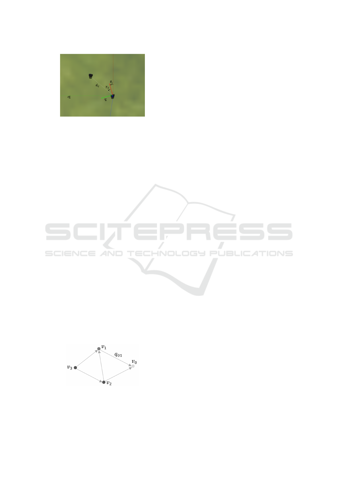
Figure 1: Illustration of agent R
i
and the frame constraints.
sesses the unicyle kinematics model as follows:
Û
x
i
(t) = v
i
(t)cos(θ
i
(t))
Û
y
i
(t) = v
i
(t)sin(θ
i
(t))
Û
θ
i
(t) = ω
i
(t) (1)
where x
i
, y
i
are the Cartesian coordinates and θ
i
(t)
is the heading angle of robot R
i
, v
i
and ω
i
are the
control inputs for linear velocity and the angular ve-
locity about the inertial z-axis, respectively (Fig. 1).
Each robot R
i
comprises onboard sensing and compu-
tational units, and the robots do not interact or com-
municate between each other or with a ground station
except for active sensing (e.g., distance sensing by ul-
trawideband (UWB) sensors).
The local sensing and communication interactions
among agents in a MRS can be described with a
graph. We define a leader-follower directed graph
G = (V, E) among the agents of the swarm S. Each
vertex i ∈ V represents an agent R
i
in S while each
directed edge
−−−→
(i, j) ∈ E from i to j implies the dis-
tance constraint d
ij
between R
i
and R
j
. Particularly,
we constrain our study to the minimally persistent
graphs which are minimally rigid and constraint con-
sistent. Such a directed graph can be generated us-
ing the Henneberg construction method such that no
vertex has more than two outgoing edges (Anderson
et al., 2008).
Denote a formation framework F = (S, G, Q) for
the swarm S along with the underlying graph structure
G and the desired (constraint consistent) distance con-
figuration Q = {q
ij
|
−−−→
(i, j) ∈ E}. We assume a leader-
Figure 2: The underlying minimally persistent constraint
graph used in this work. The leader node v
0
has no dis-
tance constraint to satisfy whereas the first follower node v
1
has one constraint and the second follower node v
2
has two
constraints.
first follower formation such that vertex v
0
has no
outgoing edge, and thus it does not have any restric-
tion on the mobility. The vertex v
1
has one outgoing
edge toward v
0
which implies that it can reside at any
point on the circle with the center at v
0
and radius
q
01
(Fig. 2). Finally, each vertex v
i
, i ∈ {2, . . ., N }
has exactly two outgoing edges toward its leader set
{
v
i−2
, v
i−1
}
, which implies that it has two distance
constraints q
i−2,i
, q
i−1,i
to satisfy. The graph G con-
structed by this operation constitutes a minimally per-
sistent graph where the entire vertex set can move
up to translation and rotation as long as all distance
constraints in Q are satisfied. We assign robot R
0
as
the leader, R
1
as the first follower, and the remain-
ing robots R
i
, i ∈ {2, . . ., N } as the second follow-
ers. Therefore, in the formation F = (S, G,Q), if the
follower robots R
i
, i ∈ {1, . . ., N } satisfy the distance
constraints q
ij
∈ Q, the entire formation will move as
a whole forming the shape dictated by Q. Notably,
the underlying graph G does not depend on the robot
motion model. Indeed, the original rigid formation
control algorithms are designed for point agent kine-
matics, e.g., holonomic agents. Here, we will modify
these control algorithms to apply on non-holonomic
agents.
2.2 Problem Formulation
We formulate our main objective as follows. Consider
the swarm S = {R
0
, R
1
, ..., R
N
}, N ≥ 2, and the leader-
first follower formation framework F = (S, G, Q) de-
fined above. We assume that all agents in the swarm
rely on their onboard resources solely, there is no
ground station, and explicit inter-robot communica-
tion is not available. Particularly, robot R
0
is equipped
with a UWB anchor sensor whereas robot R
1
is
mounted with a monocular camera and a UWB sen-
sor. Each of the remaining robots {R
2
, ..., R
N
} is
equipped with a 2D LIDAR sensor. Thus, the sens-
ing mechanism of the robots consists of heterogene-
ity. The goal is to design (i) a relative localization
solution for the given system and (ii) a distributed
control law for the robots to converge from suitable
initial conditions to a desired formation configuration
imposed by F = (S, G, Q). In the sequel, we consider
three-robot case (N = 2) as a prototype model not-
ing that the proposed framework is scalable to more
robotic agents. In Section 5 we discuss the practical
details for extension to more number of robots.
ICINCO 2022 - 19th International Conference on Informatics in Control, Automation and Robotics
332
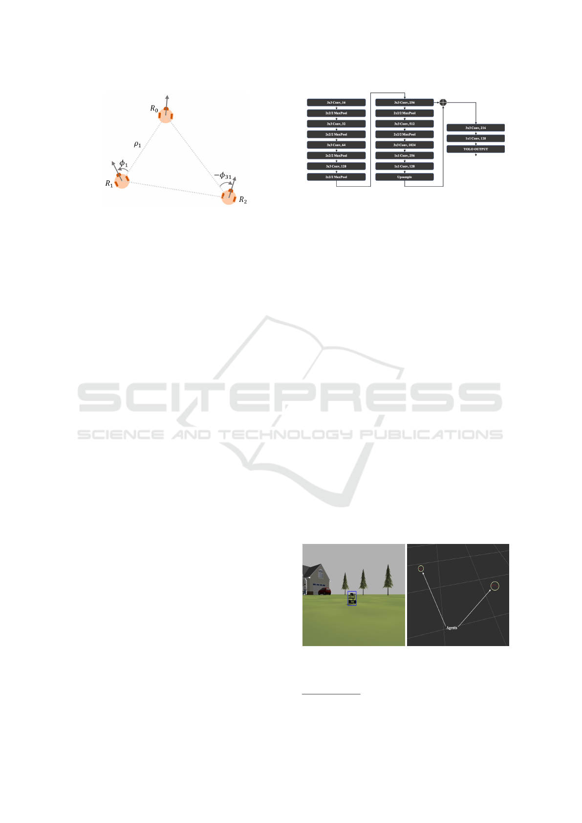
Figure 3: The top-view of three-robot system with the polar
dynamics variables.
3 SENSOR NETWORK
We now present the relative localization solution
and study the features of the sensors mounted on
the robots, namely ultrawideband (UWB) sensors,
monocular camera, and 2D LIDAR sensors. We
model the hybrid usage of these sensors in our local-
ization system which is solely dependent on onboard
sensors and does not exploit any external infrastruc-
ture.
Distance and vision measurements can be ex-
ploited in a complementarily and efficiently manner
to acquire the characteristics of the localized target.
Particularly, UWB sensors and cameras can act as
dual sensors to provide a solid framework for multi-
robot localization. On one side, UWB sensors op-
erate with high bandwidth capability and generate
accurate omnidirectional range measurements utiliz-
ing the time-of-flight (TOF) method. On the other
side, a monocular camera empowered with the re-
cent advancements in computer vision and deep learn-
ing techniques can be applied for the visual detec-
tion of a leader robot by a follower robot. Partic-
ularly, by utilizing the convolutional neural network
(CNN)-based detection methods, one can accurately
extract a relative bearing between two robots. More-
over, since most commercial versions of these sensors
are lightweight, they can be implemented on many
unmanned ground vehicles (UGVs) and unmanned
aerial vehicles (UAVs) by maintaining feasibility.
We use a pair of UWB sensors, one anchor on
robot R
0
and one tag on robot R
1
, together with a
monocular camera on R
1
to provide an efficient local-
ization system for the follower robot R
1
. We acquire
the distance q
01
between R
0
and R
1
from the UWB
sensors while the monocular camera is used to extract
the bearing angle φ
1
(Fig. 3).
Furthermore, we propose a CNN model to suc-
cessfully detect the leader robot R
0
with a monocular
camera on robot R
1
. Recently, deep learning tech-
Figure 4: The YOLO Tiny architecture used in the training.
niques have far surpassed the traditional computer vi-
sion methods. For instance, in a target tracking task,
the classical feature invariant extraction followed by
key point matching may not yield precise detection
results, particularly when the object is viewed from
only one angle and the sensor and the target object
are in motion (O’Mahony et al., 2019). In contrast,
CNN has been shown to be more effective in dynam-
ics scenarios. We particularly utilize the YOLO v3-
Tiny
1
, which is an improvement over the previous
CNN architectures such as Faster-RCNN (Ren et al.,
2015) and YOLO-v3 (Redmon and Farhadi, 2018)
with its remarkably light and robust structure adapted
for dynamic environments. Consequently, this net-
work is more suitable for real-time detection with on-
board limited resources. We redesign the structure of
the network to accommodate our single class output
and tune the network hyperparameters (Fig. 4). By
combining the UWB distance measurements with the
bearing data generated by the YOLO v3-Tiny detec-
tion, we generate the relative position p
01
in the body
frame of robot R
1
. The object detection module yields
bounding boxes of the detected objects, and the image
size can be extracted from the monocular camera. Us-
ing this intuition, we derive the relative bearing from
the target using the middle pixel of the bounding box
(Fig. 5a).
2D LIDARs offer a practical detection solution for
small-sized robots with limited payload and low en-
(a)
(b)
Figure 5: Simulation images captured in Gazebo: (a) De-
tection in the simulation environment, (b) 2D LIDAR active
localization of two agents from point clouds.
1
https://pjreddie.com/darknet/yolo/
Practical Formation Acquisition Mechanism for Nonholonomic Leader-follower Networks
333

ergy consumption. Moreover, since the motion capa-
bility of nonholonomic robots is restrained by nonlin-
ear constraints, large field-of-view of the 2D LIDARs
provides a vital advantage on this type of robots.
Therefore, we opt for a 2D LIDAR sensor on the sec-
ond follower robots R
i
, i ∈ {2, ..., N}. A second fol-
lower robot R
i
is to maintain the distances toward its
leaders {R
i−2
, R
i−1
}. Thus, it calculates the relative
location toward {R
i−2
, R
i−1
} using the laser scan point
cloud and an iterative cluster algorithm. The aim is to
highlight the target agent within the range scan of the
sensor and find the relative positions p
02
, p
12
in the
body frame of robot R
i
. We first convert the raw scan
data to point cloud in 2D to differentiate the robots
R
0
, R
1
from the surroundings. Then we separate the
robots with a threshold found empirically to segment
the robot point clouds into clusters and eliminate the
remaining laser scans (Fig. 5b).
4 DISTRIBUTED FORMATION
CONTROL SCHEME
We have presented a relative localization system for
the robots to compute the relative position toward
the leader agents using onboard sensors. We aim
at putting these techniques into practice in two dis-
tributed formation control schemes. The first exploits
the onboard fusion of odometer data to be able to con-
trol the swarm on a Euclidean plane whereas the sec-
ond generates a control mechanism to satisfy the re-
quirements on the relative quantities by excluding the
need for the magnetic sensing aids.
4.1 Generic Control Scheme
In contrast to the holonomic mobility, the agent model
(1) inherits nonholonomic constraints on the speeds.
Inspired by the control scheme of (Fidan et al., 2012),
we design our controller for the holonomic kinemat-
ics then convert the speed commands to a form which
can be applied in the nonholonomic model. Denote
the desired control input required to steer a holonomic
agent toward its desired location by u
d
=
v
d
x
, v
d
y
>
.
Then, one can adjust the nonholonomic control mech-
anism as follows:
u
d
i
(t) = v
i
(t)
cos(θ
i
(t)
sin(θ
i
(t)
, (2)
ω
i
(t) = k
ω
(θ
i
(t) − θ
d
i
(t)) +
Û
θ
d
i
(t), (3)
where k
ω
< 0 is a proportional gain, θ
d
i
(t) =
atan(v
d
y
(t)/v
d
x
(t)) is the desired heading of robot R
i
,
atan(·) is the four-quadrant arc-tangent function, and
Û
θ
d
i
=
Û
v
d
y
v
d
x
−
Û
v
d
x
v
d
y
(v
d
x
)
2
+ (v
d
y
)
2
if u
d
, 0
0 otherwise.
(4)
By using the relation in (2), that is ku
d
i
(t)k = v
i
(t), we
can choose the linear speed v
i
(t) as a proportion of the
desired speed for the holonomic agent, while the an-
gular speed can be directly used as in (3). The term
Û
θ
d
i
adds a derivative gain action effect in (3). However,
in our real experiments, we did not observe signifi-
cant effect of the term
Û
θ
d
i
. Thus, we set
Û
θ
d
i
(t) = 0 in
our evaluations. We now derive the control inputs for
the three types of robots in the swarm.
Leader. Since out-degree of the leader robot R
0
is
two, it has two degrees of freedom for mobility and
is not confined to any distance constraint toward any
other robot in the swarm. The leader is stationary dur-
ing a formation acquisition task. For flocking tasks, it
can be assigned a constant control input.
First Follower. With the out-degree equals one,
robot R
1
is to maintain a desired distance toward
the leader R
0
. Since we use two sensing modalities,
which are UWB distance sensing and vision sensing,
robot R
1
is able to sense and control both distance
and bearing toward R
0
, which both maintains rigid-
ity and fixes the formation orientation. We propose a
two-step control law as follows. Since the monocular
camera on robot R
1
is restrained on the field of view
(FOV), it may not be able to detect the leader R
0
when
it is out of the FOV. In such a scenario, we rotate R
1
with constant angular velocity (and zero linear veloc-
ity) until it sees the leader within the range, assuming
that the initial distance between robot R
0
and R
1
al-
lows detection. Upon detection from the CNN model,
the robot R
1
moves to a point which satisfies the dis-
tance constraint d
01
= kp
0
− p
1
k. Denote the distance
error by
e
01
= kq
01
k − d
01
, (5)
and the relative position between robots R
0
and R
1
by
z
01
=
p
x
01
, p
y
01
>
, (6)
where p
x
01
and p
y
01
are respectively the relative dis-
placement on the x and y axes in the local frame of
R
1
. We propose the following control input for R
1
:
u
d
1
(t) = k
v
e
01
(t)z
01
(t), (7)
θ
d
1
(t) = θ
1
(t) − φ
01
(t) + θ
o f f
, (8)
where k
v
< 0 is the proportional gain, φ
01
∈ [−π, π)
is the bearing angle derived from the object detection,
ICINCO 2022 - 19th International Conference on Informatics in Control, Automation and Robotics
334

and θ
o f f
∈ [−π, π) is a constant value that represents
the offset between the robot body frame and the cam-
era frame. The offset parameter θ
o f f
allows the sen-
sor to have a different orientation than the robot body
frame.
Second Followers. The second follower robots
have two constraints in the constraint graph G. In
our three-robot system, the second follower R
2
tries
to maintain the distance constraints d
02
and d
12
to-
ward robots R
0
and R
1
. We use the following control
law for R
i
, i ∈ 2, . . ., N:
u
d
i
(t) = k
v
Õ
j ∈N
i
e
ij
z
ij
(9)
θ
d
i
(t) =
Õ
j ∈N
i
θ
i
(t) − φ
ij
(t)
+ θ
o f f
(10)
where k
v
< 0 is the proportional gain, N
i
is the neigh-
bors of R
i
in the graph G, φ
ij
∈ [−π, π) is the bearing
angle between R
i
and R
j
measured in the body frame
of the second follower R
i
, e
ij
= kq
ij
k − d
ij
is the dis-
tance error, and
z
ij
=
h
p
x
ij
, p
y
ij
i
>
(11)
is the relative position between R
i
and R
j
in the body
frame of R
i
.
4.2 Control Law without Magnetic
Sensing
In the previous section, we have derived a distributed
control mechanism for the three types of robots in the
MRS S. The control laws for robots R
1
and R
2
heavily
rely on the odometer data which is produced by fusing
the IMU and magnetometer measurements. However,
in some workspace environments, magnetometer sen-
sors can be affected by strong electromagnetic vari-
ations, thus the readings may be unreliable and have
low SNR. In such scenarios, the entire system may
yield poor localization and control performance. To
avoid this issue, one needs to derive the control laws
directly based on the exteroceptive sensors.
Assuming the leader robot R
0
is stationary, con-
sider the polar dynamics between robots R
0
and R
1
as
follows:
Û
ρ
1
= −¯v
1
cos(φ
1
)
Û
φ
1
=
¯v
1
ρ
1
sin(φ
1
) + ω
1
(12)
where ρ
1
= kq
01
k and φ
1
= atan(x
0
− x
1
, y
0
− y
1
) is the
relative bearing angle (Fig. 3). Thus, the dynamics
(12) allows to control the distance and bearing an-
gle directly by adjusting the control inputs ¯v
1
, ω
1
at
the expanse of reducing the controllable degree-of-
freedom to two. Thus, the formation objective can
be achieved, but the robot cannot be steered to any
location on the plane. However, since formation ac-
quisition can be satisfied by setting only the distance
and bearing to their desired values, the dynamics (12)
remains a suitable model for our main objective. We
aim at devising a control law so that the distance and
bearing toward the leader converge to their desired
values.
We propose the following control law for the first
follower:
¯v
1
= sat(K
v
|e
ρ
|,0, v
up
), (13)
ω
1
= sat(K
ω
e
φ
, −ω
up
, ω
up
),
where K
v
, K
ω
, v
up
, ω
up
> 0 are design constants,
sat(a, ¯a, a) is a saturation function such that if a ≥ ¯a,
then a = ¯a, and if a ≤ − ¯a, then a = − ¯a, and
e
ρ
= ρ
1
− ρ
des
1
, e
φ
= φ
1
− φ
des
1
,
with ρ
des
> 0 and φ
des
being the desired distance and
bearing values, respectively. If φ
1
(t) ∈
[
−π/2, π/2
)
,
the controller (13) steers R
1
toward the desired loca-
tion imposed by the constraints ρ
des
1
, φ
des
1
. We assume
that initially robot R
0
resides in the FOV of the camera
of robot R
1
. If such an initialization is not possible,
one can purely rotate R
1
with a constant angular ve-
locity in one direction until robot R
0
enters the FOV
of the camera of robot R
1
then apply (13) for forma-
tion acquisition. Thus, we expect that the robot con-
verges to its desired location, leaving the stability and
convergence analysis to future works.
5 EVALUATION
In this section, we demonstrate our CNN training ex-
perience and the results of our simulations and real
world experiments. Finally, we discuss the practical
aspects.
5.1 CNN Training
We trained an object detection model for each of the
simulation and real experiments. While standard ob-
jects can be found in the existing pool of dataset such
as COCO (Lin et al., 2014), we did not have a col-
lection of image dataset for our particular object of
interest, Turtlebot3. Therefore, we first constructed
a dataset for the simulation and the real experiment.
We collected 337 images of the Turtlebot3 from the
simulation and 501 images from the real robot. Then,
we conducted the manual labeling process, i.e., as-
signing individual bounding boxes to the Turtlebot3
Practical Formation Acquisition Mechanism for Nonholonomic Leader-follower Networks
335
(a)
(b)
Figure 6: Sensors view in experiment: a) A detection from
Jetson nano: A view from R
1
, b) A scan from the LDS LI-
DAR seen by robot R
2
.
sections of the images. During the training phase, we
randomly split the dataset into the training, validation,
and testing sets. Then, we trained the network by se-
lecting the best observed hyperparameters, which are
a batch size of 64, a momentum of 0.9, and a learning
rate of 0.001. We obtained the final results on the test-
ing set of mean average precision (mAP@75) of 96%
on the experiments, which enabled the high precision
during experimental tests. Sample detection images
from the CNN can be seen in Fig. 5a (simulation) and
6a (experiment).
5.2 Simulation
We simulated our proposed system in Gazebo, a re-
alistic and powerful environment that allows to vi-
sualize robotic systems with similar physical prop-
erties. We used three Turtlebot3 burger robots and
onboard sensors with the following specifications: A
monocular RGB camera with FOV of 2.45 radians on
R
1
and a 2D LIDAR with 360 FOV and a range of
6.28 meters on R
2
. We processed the LIDAR data us-
ing the point cloud package from robot operating sys-
tem (ROS) and used OpenCV
2
for post-processing the
YOLO model inference. We mimic the UWB sensor
measurements with the distance values obtained from
(a)
0 10 20 30 40 50
Time (s)
-2.5
-2
-1.5
-1
-0.5
0
0.5
1
1.5
(b)
Figure 7: Formation acquisition by expansion simulation:
a) Trajectories of the agents, b) the inter-robot distance er-
rors.
2
https://opencv.org/opencv-4-4-0/
(a)
0 10 20 30 40 50 60
Time (s)
-1.5
-1
-0.5
0
0.5
1
1.5
2
2.5
(b)
Figure 8: Formation acquisition by contraction simulation:
a) Trajectories of the agents, b) the inter-robot distance er-
rors.
Gazebo with added zero-mean Gaussian noise, i.e.,
q
ij
(t) = ¯q
ij
(t) + η
ij
(t) where η
ij
∼ N(0, σ
2
) with σ the
standard deviation.
In the simulations, we evaluated the setup for
two formation objectives: Contraction and expansion.
We used the generic formation control scheme us-
ing odometry data. These two key actions aimed at
demonstrating the flexibility of the agents to adapt to
different scenarios independent of the initial condi-
tions. The first assessment requires the robots to build
a formation with smaller relative distances than the
initial values whereas the second evaluation starts the
formation from a configuration where the distances
are smaller than their desired values. The trajectories
and the relative distance errors are depicted in Fig. 8
and Fig. 7. We observed an exponential convergence
to the desired configuration and fast decrement of the
distance errors e
ij
. Also, we obtained a CNN detec-
tion rate greater than 90% on R
1
in all simulations,
which proved efficiency of the proposed localization
method.
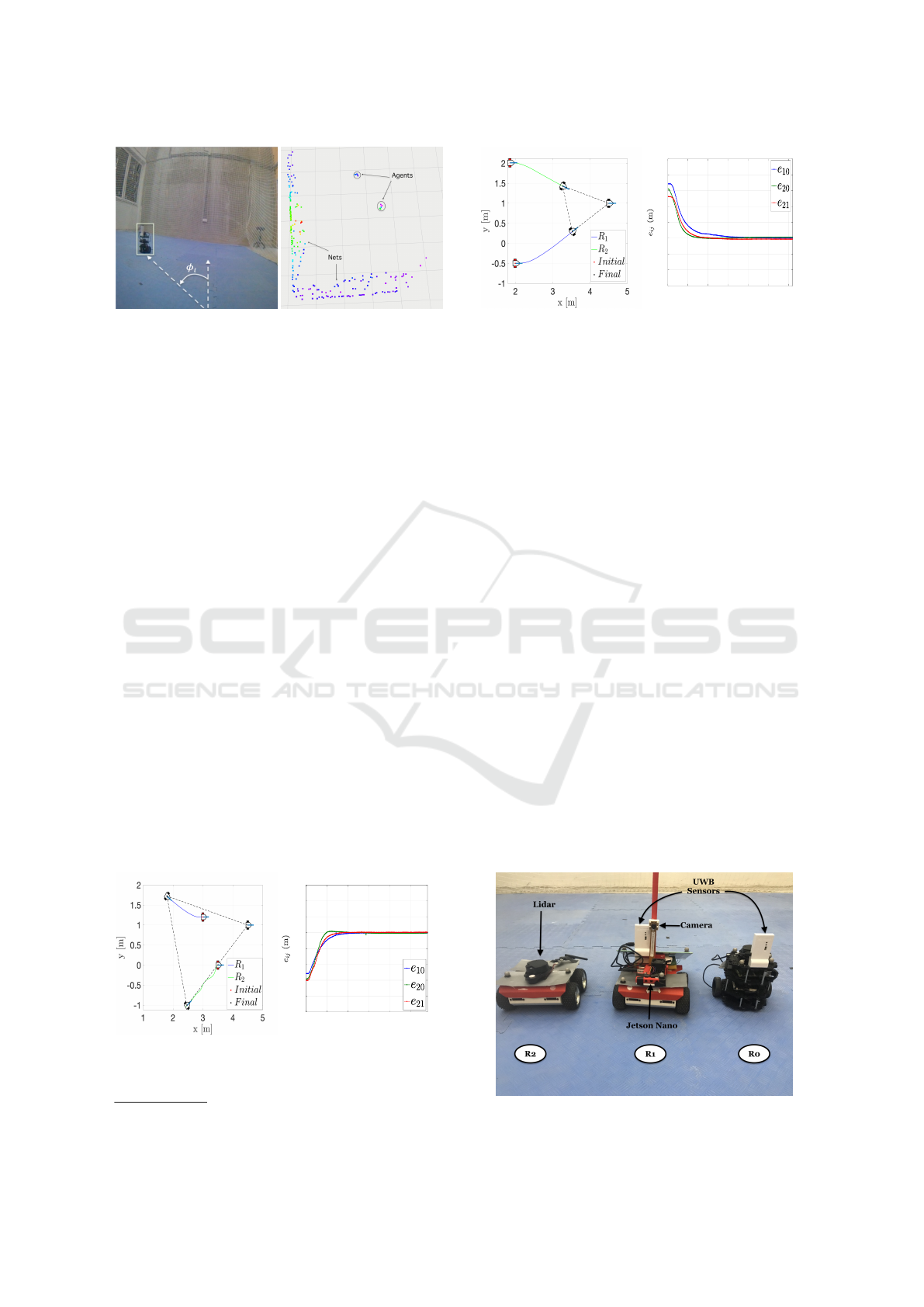
5.3 Experiments
We performed a series of tests in an indoor lab envi-
ronment where GPS is not available. The three-robot
Figure 9: The robots and hardware used in the experiment.
ICINCO 2022 - 19th International Conference on Informatics in Control, Automation and Robotics
336
system comprised a Turtlebot3 as the leader (R
0
) and
two Rosbots as the first-follower (R
1
) and the second-
follower (R
2
), respectively (Fig. 9). We equipped the
robots with the sensor network explained in Section 3.
Particularly, we mounted a pair of DWM1001 UWB
modules on the leader and the first follower to pro-
duce the relative distance between them. Also, we
mounted a CSI camera through an Intel Jetson Nano
computer on the first follower for bearing detection.
We calibrated the camera to remove the distortions
and reduced the image size from (3280 × 2464) to
(416 × 416) which is the input to the CNN model.
This resizing operation eliminates the need for extra
pre-processing operations on the image before the de-
tection, and eventually, reduces the overall detection
time. With its GPU cores, Jetson Nano performed the
model inference using the accelerated TensorRT and
produced a detection speed of up to 60 ms which was
reasonable for our platform. Finally, we equipped the
second Rosbot with a 2D LDS LIDAR with the FOV
of 360 degrees and the maximum range of 3.5 meters.
We recorded the ground truth pose data of the robots
with a VICON motion capture system for illustration
purposes. The motion capture system data was not
used in any part of our algorithms.
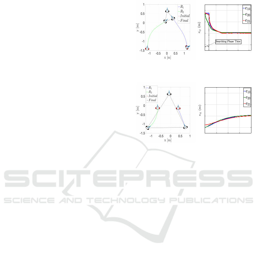
We evaluated the proposed framework on the
three-robot system defined above relying on their
onboard resources. The results of a contraction
experiment is illustrated in Fig. 10. In this ex-
periment, the robots were initiated from p
0
(0) =
[0.02, 0.62, 0.0]
>
meters, p
1
(0) = [1.14, −1.33, 0.0]
>
meters, and p
2
(0) = [−1.13, −1.41, 0.0]
>
meters with
different heading angles which are also denoted in
Fig. 10. Initially, the leader robot R
0
was not in the
FOV of the robot R
1
. Thus, R
1
first rotated with
zero linear speed and waited for the leader to enter
its camera FOV. Once R
1
is detected with the CNN
at the 36th second, it started approaching R
0
based
on the control rule (7). On the other hand, robot R
2
segmented the LIDAR scans to generate clusters for
robots R
0
and R
1
. After building the clusters, robot R
2
generated the distance estimates q
02
, q
12
. We assumed
that initially the robots R
0
and R
1
were present within
the laser range. We depict a sample point cloud view
of the scans in Fig. 6b. There were nets on the left and
rear sides of R
2
which can be clearly seen in Fig. 6b,
which we removed with a simple pre-processing in
the algorithm. We observed that the robots converged
to the desired configuration which are d
ij
= 0.5 meters
for all i, j (Fig. 10b), and the error remained bounded
for sufficiently long time (around 400 seconds). We
conjecture that the relatively small error in the dis-
tances were due to the sensor noises. For instance,
the UWB distance readings from this experiment with
(a)
0 100 200 300 400
Time (s)
-1
0
1
2
(b)
Figure 10: Contraction experiment: a) Trajectories of the
agents, b) the inter-robot distance errors.
(a)
0 20 40 60 80
Time (s)
-1
0
1
2
(b)
Figure 11: Expansion Experiment . a) Trajectories of the
agents. b) The relative distance errors.
its ground truth are given in Fig. 12b, which shows a
noise with a variance of around 0.05 meters. Nev-
ertheless, the framework exhibited high performance
in terms of formation acquisition. A similar perfor-
mance can be seen in the formation expansion exper-
iment in Fig. 11.
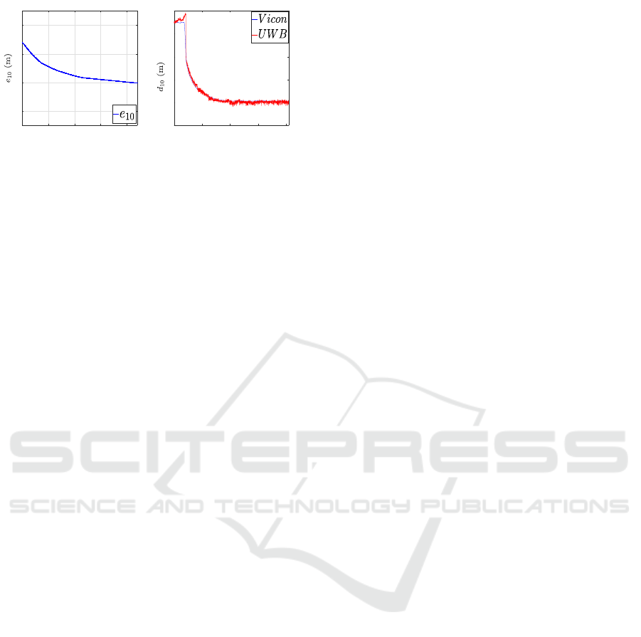
Furthermore, we evaluated the case where the
magnetometer is not available for the first follower
(Fig. 12a). In this experiment, robot R
1
used the
controller (13) and was able to converge toward the
desired configuration. This result reflects the flexi-
bilty of the proposed framework for magnetometer-
less settings. Although not presented here, another
controller which does not depend on magnetometer
sensor can be designed for the second follower robot
as well, which is one of our future objectives.
We now discuss some practical details which were
important when transitioning from simulations to ex-
periments. In our framework, the second follower
robot R
2
relies on LIDAR solely. However, when
LIDAR detects another object in the workplace, the
two clusters for localizing the robots R
0
and R
1
may
not be generated precisely, which may deteriorate the
performance. Therefore, we emphasize the assump-
tion that the workplace needs to be free of any other
object. If such a condition cannot be met, further
post-processing of LIDAR measurements would be
needed. Furthermore, although we have provided a
general framework for N + 1-robot swarms, we have
Practical Formation Acquisition Mechanism for Nonholonomic Leader-follower Networks
337
0 25 50 75 100
Time (s)
-1
0
1
2
(a)
0 100 200 300 400
Time (s)
0
0.5
1
1.5
2
2.5
(b)
Figure 12: a) The error on R
1
during a formation contrac-
tion without magnetometers, b) A Comparison of UWB
sensor data with ground truth from Vicon capture system.
focused on a three-robot setup in evaluations. When
there are more than one second-follower robots, i.e.,
when robots R
i
,i ∈ {3, . . ., N} are added to the sys-
tem, a more advanced LIDAR post-processing would
be necessary to discriminate the two leader robots for
each second-follower.
Moreover, although UWB sensors provide accu-
rate distance data in most environments, they may
generate low signal-to-noise ratio if not calibrated
properly. We suggest finding the correct bias and
noise variance values of the UWB sensors with a
proper calibration. In our experiments, we used a
basic calibration which requires to place the UWB
pair at locations with certain distances and collecting
data for a certain time. However, UWB distance mea-
surements may vary significantly with varying angu-
lar placements of the sensors and ambient factors.
We emphasize the importance of UWB calibration for
more precise evaluations.
6 CONCLUSIONS
We have investigated the practical formation control
problem for MRS using onboard sensors. We have
proposed a systematic framework including a local-
ization module and a control module. The local-
ization module consists of a bearing angle deriva-
tion based on a YOLOv3-Tiny architecture with a
monocular camera and a systematic clustering for a
2D LIDAR. The control module consists of a set of
distributed formation control laws for three types of
robots in the leader-follower hierarchy. Furthermore,
we have proposed a control method which does not
use of a magnetometer sensor which is known to
generate unreliable sensor readings in some environ-
ments. We have evaluated the framework on non-
holonomic ground robots for the formation contrac-
tion and expansion objectives in both simulations and
experiments. The high performance obtained in a se-
ries of experiments indicates the applicability of the
proposed solution. Future research may include ex-
tension of the framework for dynamic path planning
and obstacle avoidance for the whole swarm using on-
board resources. Also, LIDAR data post-processing
to discriminate the leader robots in the FOV needs to
be studied to scale up the swarm size.
ACKNOWLEDGEMENTS
This paper has been produced benefiting from
the 2232 International Fellowship for Outstanding
Researchers Program of T
¨
UB
˙
ITAK (Project No:
118C348). However, the entire responsibility of the
paper belongs to the owner of the paper. The financial
support received from T
¨
UB
˙
ITAK does not mean that
the content of the publication is approved in a scien-
tific sense by T
¨
UB
˙
ITAK.
REFERENCES
Abdelkader, M., G
¨
uler, S., Jaleel, H., and Shamma, J. S.
(2021). Aerial swarms: Recent applications and chal-
lenges. Current Robotics Reports, 2(3):309–320.
Almadhoun, R., Taha, T., Seneviratne, L., Dias, J., and Cai,
G. (2016). A survey on inspecting structures using
robotic systems. International Journal of Advanced
Robotic Systems, 13(6):1729881416663664.
Anderson, B. D., Yu, C., Fidan, B., and Hendrickx, J. M.
(2008). Rigid graph control architectures for au-
tonomous formations. IEEE Control Systems Maga-
zine, 28(6):48–63.
Choi, Y. H. and Kim, D. (2021). Distance-based forma-
tion control with goal assignment for global asymp-
totic stability of multi-robot systems. IEEE Robotics
and Automation Letters, 6(2):2020–2027.
Chung, S.-J., Paranjape, A. A., Dames, P., Shen, S., and
Kumar, V. (2018). A survey on aerial swarm robotics.
IEEE Transactions on Robotics, 34(4):837–855.
De Queiroz, M., Cai, X., and Feemster, M. (2019). Forma-
tion control of multi-agent systems: A graph rigidity
approach. John Wiley & Sons.
Fidan, B., Gazi, V., Zhai, S., Cen, N., and Karatas¸, E.
(2012). Single-view distance-estimation-based forma-
tion control of robotic swarms. IEEE Transactions on
Industrial Electronics, 60(12):5781–5791.
Guler, S., Abdelkader, M., and Shamma, J. S. (2020). Peer-
to-peer relative localization of aerial robots with ul-
trawideband sensors. IEEE Transactions on Control
Systems Technology, pages 1–16.
Kabore, K. M. and G
¨
uler, S. (2021a). Deep learning based
formation control of drones. In Deep Learning for
Unmanned Systems, pages 383–413. Springer.
Kabore, K. M. and G
¨
uler, S. (2021b). Distributed for-
mation control of drones with onboard perception.
IEEE/ASME Transactions on Mechatronics.
ICINCO 2022 - 19th International Conference on Informatics in Control, Automation and Robotics
338

Lin, J., Miao, Z., Zhong, H., Peng, W., Wang, Y., and Fierro,
R. (2020). Adaptive image-based leader–follower for-
mation control of mobile robots with visibility con-
straints. IEEE Transactions on Industrial Electronics,
68(7):6010–6019.
Lin, T.-Y., Maire, M., Belongie, S., Hays, J., Perona, P.,
Ramanan, D., Doll
´
ar, P., and Zitnick, C. L. (2014).
Microsoft coco: Common objects in context. In Euro-
pean conference on computer vision, pages 740–755.
Springer.
Liu, X., Ge, S. S., and Goh, C.-H. (2018). Vision-based
leader–follower formation control of multiagents with
visibility constraints. IEEE Transactions on Control
Systems Technology, 27(3):1326–1333.
Nguyen, T.-M., Qiu, Z., Cao, M., Nguyen, T. H., and Xie,
L. (2020). Single landmark distance-based navigation.
IEEE Transactions on Control Systems Technology,
28(5):2021–2028.
Oh, K.-K., Park, M.-C., and Ahn, H.-S. (2015). A survey of
multi-agent formation control. Automatica, 53:424–
440.
O’Mahony, N., Campbell, S., Carvalho, A., Harapana-
halli, S., Hernandez, G. V., Krpalkova, L., Riordan,
D., and Walsh, J. (2019). Deep learning vs. tradi-
tional computer vision. In Advances in Intelligent Sys-
tems and Computing, pages 128–144. Springer Inter-
national Publishing.
Redmon, J. and Farhadi, A. (2018). Yolov3: An incremental
improvement. arXiv preprint arXiv:1804.02767.
Ren, S., He, K., Girshick, R., and Sun, J. (2015). Faster
r-cnn: Towards real-time object detection with region
proposal networks. In Advances in neural information
processing systems, pages 91–99.
Saska, M., Baca, T., Thomas, J., Chudoba, J., Preucil,
L., Krajnik, T., Faigl, J., Loianno, G., and Kumar,
V. (2017). System for deployment of groups of un-
manned micro aerial vehicles in gps-denied environ-
ments using onboard visual relative localization. Au-
tonomous Robots, 41(4):919–944.
Silano, G., Baca, T., Penicka, R., Liuzza, D., and Saska, M.
(2021). Power line inspection tasks with multi-aerial
robot systems via signal temporal logic specifications.
IEEE Robotics and Automation Letters, 6(2):4169–
4176.
Tian, Y., Liu, K., Ok, K., Tran, L., Allen, D., Roy, N., and
How, J. P. (2020). Search and rescue under the forest
canopy using multiple uavs. The International Journal
of Robotics Research, 39(10-11):1201–1221.
Trinh, M. H., Zhao, S., Sun, Z., Zelazo, D., Anderson,
B. D., and Ahn, H.-S. (2018). Bearing-based for-
mation control of a group of agents with leader-first
follower structure. IEEE Transactions on Automatic
Control, 64(2):598–613.
Vrba, M. and Saska, M. (2020). Marker-less micro aerial
vehicle detection and localization using convolutional
neural networks. IEEE Robotics and Automation Let-
ters, 5(2):2459–2466.
Walter, V., Saska, M., and Franchi, A. (2018). Fast mutual
relative localization of UAVs using ultraviolet LED
markers. In 2018 International Conference on Un-
manned Aircraft Systems (ICUAS). IEEE.
Zhao, S. and Zelazo, D. (2019). Bearing rigidity theory and
its applications for control and estimation of network
systems: Life beyond distance rigidity. IEEE Control
Systems Magazine, 39(2):66–83.
Practical Formation Acquisition Mechanism for Nonholonomic Leader-follower Networks
339
