
External Force Adaptive Compensator for Serial Manipulators
Albert Demian
a
and Alexander Klimchik
b
Center for Technologies in Robotics and Mechatronics Components, Innopolis University,
Universitetskaya st., Innopolis, Russian Federation
Keywords:
Static Balancing, Force Compensation, Variable Payload, Manipulator Design.
Abstract:
We propose a preliminary design concept for the external force compensator. An arrangement of lever-wheel
arrangement with a group of springs producing counter torque to compensate for external force. The springs
are fixed on adjustable pivot points to allow compensation of a range of payloads. We introduce the use of self-
locking worm gears to ensure the compensator’s torque is purely applied on either the wheel or the lever. We
investigated the compensator design with a 2-DOF manipulator which consists of two orthogonal rotational
joints. We present a design methodology to the compensator together with a selection of spring coefficients to
match a certain range of payloads. Results of the simulation show complete compensation of external force is
possible as compensation of certain components of the force vectors.
1 INTRODUCTION
Serial robotic arms are known for their various appli-
cations. The main drawback of using robot manipu-
lators is the large mass of the links which requires us-
ing high-power motors. The majority of energy con-
sumed during operation goes to compensate for the
robot’s own weight while leaving only a smaller part
to manipulate payload (Kim and Song, 2014).
Studies on gravity compensation show a variety
of approaches to passively compensate for the robot’s
weight reducing the torque required by the robot’s
joints (Arakelian, 2016). The traditional method is to
use a counterweight (see Figure 1a) (Arakelian et al.,
2000). This method allows for increasing payloads.
However, it increases energy consumption as the total
potential energy of the manipulator is increased due
to the increased weight. Another method is to add
a single-component compensator that can be spring-
based or pneumatic-based as shown in Figure 1b.
These elements change the non-linear dynamic be-
havior of the manipulator to a different behavior due
to the introduction of their own non-linear behavior
to the manipulator’s statics and dynamics. Integrat-
ing compensators with manipulators changes stiffness
properties (Klimchik and Pashkevich, 2022). An in-
vestigation of stiffness properties and identification
of manipulators with spring-based compensators is
a
https://orcid.org/0000-0003-1318-9220
b
https://orcid.org/0000-0002-2244-1849
presented in (Klimchik et al., 2013), investigation of
stiffness properties of manipulators with pneumatic-
based compensators is presented in (Klimchik et al.,
2017). Nevertheless, compensators provide support
to the manipulator and enhance its stiffness properties
for enhanced manipulation of payload.
Other studies introduce gravity compensation us-
ing auxiliary mechanisms with springs like the one
introduced in (Gopalswamy et al., 1992). They used
a parallelogram mechanism coupled with torsional
springs to counter-balance gravitational torques in
manipulators’ joints. The advantage of using springs
is that they have lightweight hence, the increase of
the manipulator’s total potential energy is insignifi-
cant. Studies that use springs for counter-balancing
introduce various mechanisms with different types of
results. An example of compensation using an auxil-
iary mechanism is shown in Figure 1c. Some studies
show a partial reduction of gravity torques as in (Kim
and Song, 2014) where they used the parallelogram
mechanism as an auxiliary system to transform the
vertical base axis to consequent manipulator’s joints.
At each joint, a spring connects between the link and
the vertical reference frame allowing the compensa-
tion of the major part of the joint’s torque. partial
compensation of gravity torques for different types of
manipulators was considered by (Morita et al., 2003),
(Agrawal and Fattah, 2004), (Kim et al., 2016) and
(Chung et al., 2016) where planar and a spacial cases
were investigated.
The design of compensator for multi-DoF manip-
500
Demian, A. and Klimchik, A.
External Force Adaptive Compensator for Serial Manipulators.
DOI: 10.5220/0011319700003271
In Proceedings of the 19th International Conference on Informatics in Control, Automation and Robotics (ICINCO 2022), pages 500-507
ISBN: 978-989-758-585-2; ISSN: 2184-2809
Copyright
c
2022 by SCITEPRESS – Science and Technology Publications, Lda. All rights reserved
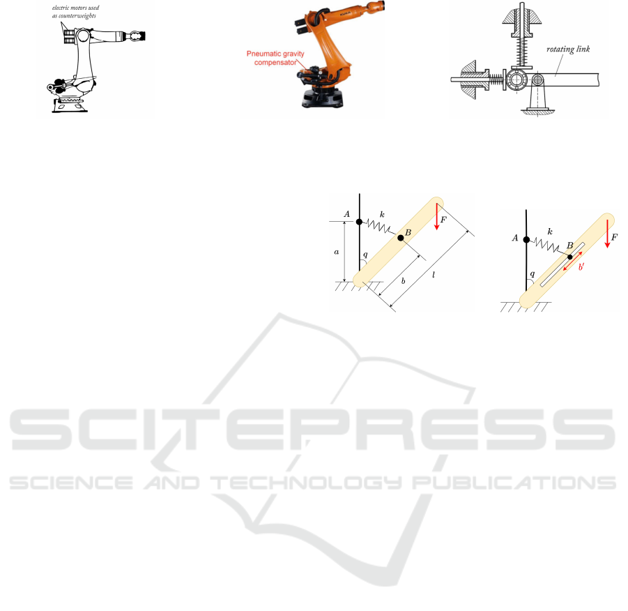
(a) Compensation using counter-
weight.
(b) Compensation using pneumatic
element.
(c) Compensation using auxiliary
mechanism.
Figure 1: Different methods for counter-balancing.
ulators is complex and increases in complexity for a
larger number of degrees of freedom. Another factor
that affects complexity is the level of compensation as
partial compensation of gravity torques is less com-
plex than complete compensation. Moreover, design-
ing a compensator for a planar case is less complex
than for a spacial case. (Cho and Kang, 2014) pro-
posed an analytical approach based on the analysis
of the eigenvalues of the potential energy of articu-
lated manipulators. The advantage of this approach is
that it shows the decoupling of torque terms and pro-
vides a systematic approach for determining the num-
ber of springs needed and their locations. Similarly
(Cho et al., 2012), (Kim and Cho, 2017), (Lin et al.,
2010) and (Chung et al., 2016) considered the com-
plexity of the spacial for complete compensation of
gravity torques. While some studies considered pla-
nar cases as in (Lin et al., 2012) and (Jhuang et al.,
2018). Some studies considered reducing the com-
plexity by introducing different components as cams
(Koser, 2009). Other studies went beyond service ma-
nipulators and considered different systems like reha-
bilitation devices as in (Nakayama et al., 2009).
In this paper, we are considering a preliminary
concept of an adaptive compensator in which a com-
bination of linear springs is integrated. The adaptation
appears in the form of adjustment of springs fixation
points in order to produce various values of counter-
torque for the same robot configuration. This aims
to compensate payload and adapt to the changes in
the payload. The concept depends on coupling robot
joints with a combination of springs producing a sum
of torque to counter the payload torque. This al-
lows complete compensation for the constant payload
around the robot’s whole workspace while being able
to re-adjust components’ stiffness to match different
payloads. A 2-DoF spacial manipulator is mounted
with the proposed compensator. We considered the
arrangement of the mechanical connections however,
we did not present calculations of transmission ratios.
The system is tested in simulation and the results to-
gether with design recommendations are presented.
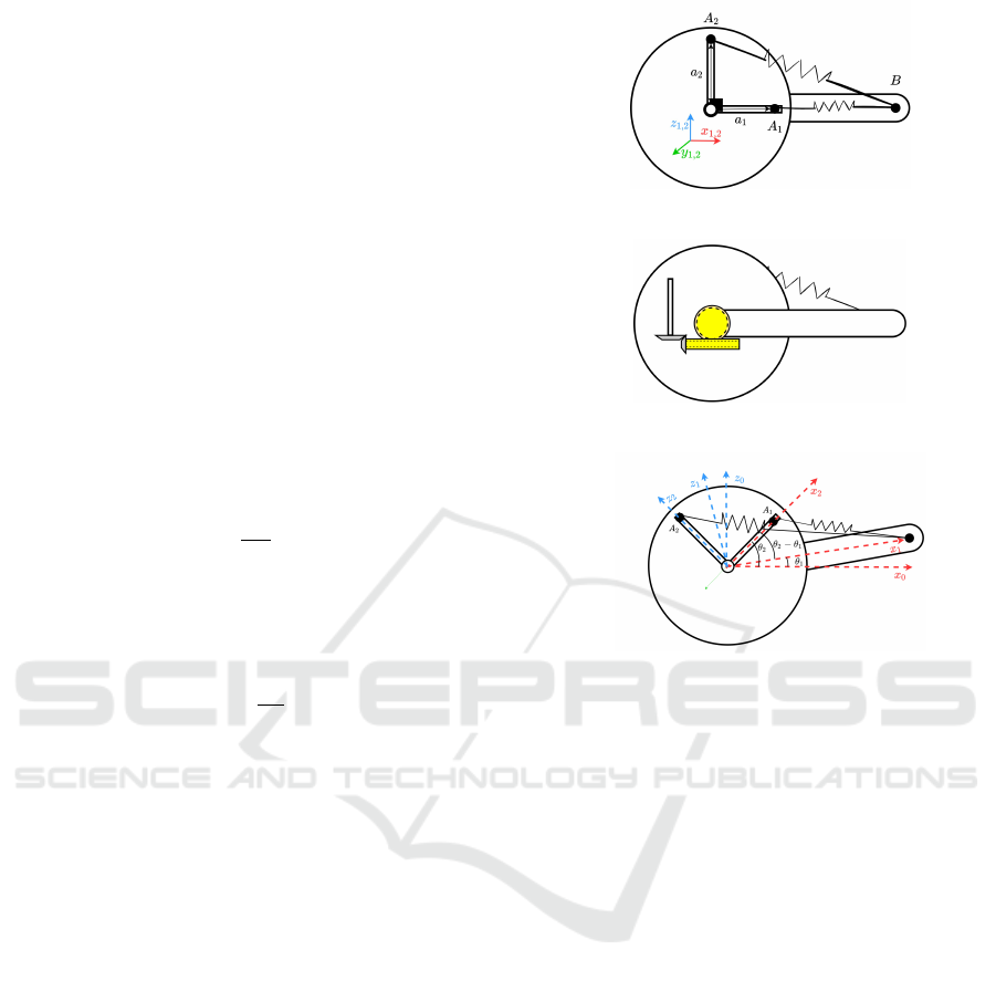
(a) A 1-DoF system with
external force and spring
suspension.
(b) Spring suspension
with an adjustable fixa-
tion point.
Figure 2: Compensation of a single-component force with
1-DoF system.
2 STATIC MODELING FOR A
SINGLE-COMPONENT FORCE
COMPENSATOR
A single-component force compensator is addressed
in this section. The goal is to show a method to com-
pensate a force component using a single spring by
adjusting one of its fixation points. Figure 2a shows
a 1-DoF system with one link of length l and rotated
with angle q. The mass of the link is not considered.
A spring with stiffness coefficient k is connected at
point A at a vertical distance a from the ground and at
point B at distance b along the link. An external force
F is applied on the tip of the link pointing downwards
making the force vector F = [0, 0,− f
z
]
T
and the tip
position as follows.
⃗
L =
l sin(q) 0 l cos(q)
T
(1)
where
⃗
L is the position vector pointing from the center
of rotation to the tip of the link.
It is possible to calculate the torque due to external
force using cross product.
τ =
⃗
L × F =
0 − f
z
l sin(q) 0
T
(2)
where τ is the torque due to external force around the
center of rotation.
External Force Adaptive Compensator for Serial Manipulators
501
A spring with proper stiffness coefficient can pro-
duce counter torque that eliminates the effect of the
force and makes the sum of torques around the joint
equals to zero at any angle q.
F
s
=
⃗
BA k (3)
where k is the spring’s stiffness coefficient,
⃗
BA is the
distance vector pointing from point B to point A rep-
resenting the extended length of the spring and F
s
is
the force produced by the spring.
τ
s
=
⃗
B × F
s
=
0 a b k sin(q) 0
T
(4)
where τ
s
is the torque produced by the spring around
the center of rotation.
As the system should be in equilibrium, the sum
of torques should be zero τ + τ
s
= 0.
a b k sin(q) = f
z
l sin(q) (5)
And accordingly we can choose the spring coeffi-
cient k.
k =
f
z
l
a b
(6)
Figure 2b shows an adjustable pivot point where
only one of the spring’s ends is fixed. By adjusting the
distance b
′
, we can achieve compensation to a range
of values of applied force.
b
′
= f
z
l
a k
(7)
This implies a linear relation between the distance
b
′
and the applied force. This means that the linear
variation of the distance b
′
can correspond to a value
range of force that can be compensated.
3 STATIC MODELING FOR A
TWO-COMPONENT FORCE
COMPENSATOR
For systems with multi-DoF, the torque applied on
a single joint due to external force depends on the
whole configuration of the manipulator. This section
aims to show a method using two springs to produce a
counter-torque that depends on two configuration an-
gles θ
1
and θ
2
. Figure 3a shows lever-wheel arrange-
ment. The lever and the wheel rotate around the same
center with angles θ
1
and θ
2
, respectively. Two points
A
1
and A
2
are fixed at some distance a
1
and a
2
from
the center of the wheel and set apart with a 90 shift.
Point B is fixed at distance b along the lever. Two
springs with coefficients [k
1
,k
2
] connect point B with
both points A
1
and A
2
, respectively.
Taking the lever rotation of the value θ
1
while the
rotation of the wheel of θ
2
. If the wheel and the lever
(a) Geometric representation of lever-wheel mechanism with
2-DoF compoensator.
(b) Geometrical representation of worm gear meshing on the
back side of the lever-wheel mechanism.
(c) A show case where the lever rotates with angle θ
1
while the
wheel rotates with angle θ2.
Figure 3: The concept of using the lever-wheel arrange-
ment.
rotate in the same direction, a value of (θ
1
− θ
2
) can
be realized. While if they rotate in opposite direc-
tions, a value (θ
1
+ θ
2
) can be realized, taking the
counter-clockwise direction as the positive direction.
Figure 3c presents realization of θ
1
− θ
2
. Taking the
lever’s reference frame where the x-axis points along
the lever, makes the position vector of points A
1
,A
2
and B as follows:
B = [b,0,0]
T
A
1
= a
1
cos(θ
1
− θ
2
) 0 sin(θ
1
− θ
2
)
T
A
2
= a
2
− sin(θ
1
− θ
2
) 0 cos(θ
1
− θ
2
)
T
(8)
The torque generated by the spring between points
A
1
and B can be formulated as follows:
τ
a
1
= k
1
· A
1
× (B − A
1
) (9)
where k
1
is the stiffness coefficient of the spring con-
necting between points A
1
and B and τ
a
1 is the torque
produced by this spring.
τ
a
1
,y
= −k
1
a
1
b sin(q
1
− q
2
) (10)
where τ
a
1
,y
is the y-component of τ
a
1
as the x and z
components equal to zero.
ICINCO 2022 - 19th International Conference on Informatics in Control, Automation and Robotics
502

Figure 4: 2DoF manipulator.
Similarly, for the spring between points A
2
and B:
τ
a
2
= k
2
· A
2
× (B − A
2
) (11)
which makes the y-component τ
a
1
,y
as follows.
τ
a
2
,y
= −k
2
a
2
b cos(q
1
− q
2
) (12)
Making the sum of torques τ
sum
around the center
of rotation as follows:
τ
sum
= τ
a
1
,y
+ τ
a
2
,y
= −k
1
a
1
bsin(q
1
− q
2
) − k
2
a
2
bcos(q
1
− q
2
) (13)
Using a self-locking worm gear ensures that the
torque is applied on the wheel and prevents the lever
from getting affected by this torque. Figure 3b shows
that the lever is coupled with a worm gear. We can
realize different values for τ
sum
by making distances
a
1
and a
2
to be adjustable as illustrated for the case in
Figure 2.
4 STATIC MODELING FOR A
FORCE COMPENSATOR FOR A
2-DoF MANIPULATOR
This section presents the use of the system proposed
in Section 3 to compensate a 3D external force act-
ing on the end effector of a 2-DoF manipulator shown
in Figure 4. It has two orthogonal rotational joints ro-
tate with joint coordinates q
1
and q
2
with links’ length
l
1
and l
2
. An arbitrary force F = [ f
x
, f
y
, f
z
]
T
is ap-
plied on the tip of the second link. The goal is to
compensate torque of the manipulator’s joints using
the system presented in Figure 3. we can calculate
the manipulator’s tip pose and the manipulator Jaco-
bian taking and arbitrary configuration Q = [q
1
,q
2
]
T
as follows:
X =
l
2
sin(q
2
)cos (q
1
)
l
2
sin(q
1
)sin (q
2
)
l
1
+ l
2
cos(q
2
)
(14)
where X is a 3D position vector representing position
of the end effector.
Then we can derive the manipulator Jacobian by
calculating the partial derivative of the vector X with
respect to joint coordinates ∂X/∂q
i
J =
−l
2
sin(q
1
)sin (q
2
) l
2
cos(q
1
)cos (q
2
)
l
2
sin(q
2
)cos (q
1
) l
2
sin(q
1
)cos (q
2
)
0 −l
2
sin(q
2
)
(15)
where J is the manipulator’s Jacobian.
The Jacobian matrix is used to map the external
force to joints’ torques by taking its transpose.
τ = J
T
F (16)
where τ is vector of joint torques [τ
1
,τ
2
]
T
and F is the
applied external force vector.
This makes torque of the joints as follows.
τ
1
= − f
x
l
2
sin(q
1
)sin (q
2
) + f
y
l
2
cos(q
1
)sin (q
2
) (17)
where τ
1
is the torque in the first joint.
τ
2
= f
x
l
2
cos(q
1
)cos (q
2
)
+ f
y
l
2
sin(q
1
)cos (q
2
) − f
z
l
2
sin(q
2
) (18)
where τ
2
is the torque in the second joint.
We can expand the torque formulas using the
trigonometric identities switching multiplication into
addition as follows:
τ
1
=
1
2
f
x
l
2
cos(q
1
+ q
2
) −
1
2
f
x
l
2
cos(q
1
− q
2
)
+
1
2
f
y
l
2
sin(q
1
+ q
2
) −
1
2
f
y
l
2
sin(q
1
− q
2
) (19)
and similarly for τ
2
τ
2
=
1
2
f
x
l
2
cos(q
1
+ q
2
) +
1
2
f
x
l
2
cos(q
1
− q
2
)
+
1
2
f
y
l
2
sin(q
1
+ q
2
) +
1
2
f
y
l
2
sin(q
1
− q
2
)
− f
z
l
2
sin(q
2
) (20)
This expansion of torque expressions shows the
similarity between those expressions and the one de-
rived from the system in Section 3. This means that
it is possible to design a combination of the system in
Figure 3a to compensate for the external force acting
on the manipulator.
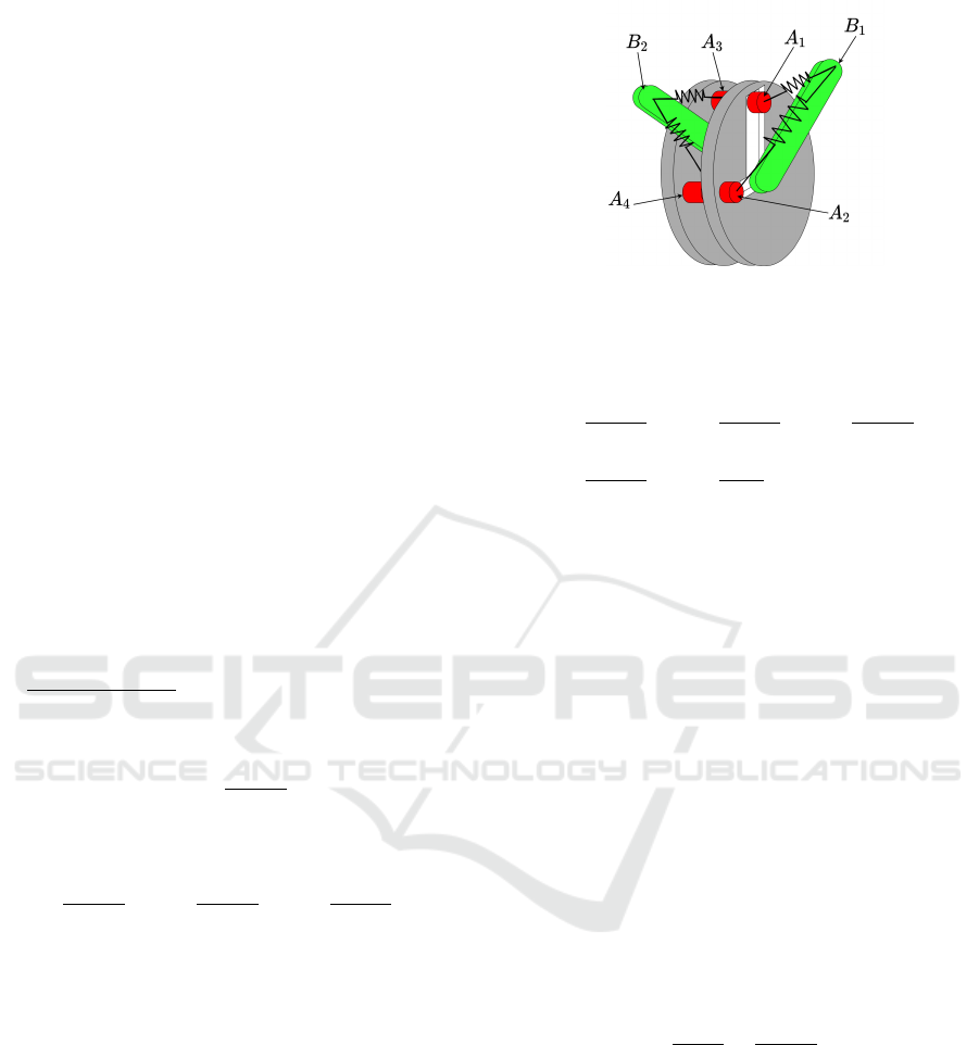
4.1 Compensator Design for the First
Joint
Using the system in Figure 3 , we can compensate for
the torque applied to the joint. The system in Fig-
ure 3c compensates for terms with angle difference
External Force Adaptive Compensator for Serial Manipulators
503
q
1
− q
2
. A second system where the level rotates in
the reverse direction can be used to compensate for
terms with angle sum q
1
+q
2
. Considering the wheels
rotate with angle q
1
and one lever rotates with an-
gle q
2
and −q
2
, respectively. This will allow real-
izing all the four terms in Eqn. (19). Each system has
a point B and 2 points A. This makes the compen-
sator for the first joint has two points B
1
and B
2
and
4 points A
1
,A
2
,A
3
and A
4
. Due to mechanical con-
straints, points A
1
,A
2
,A
3
and A
4
will be fixed to the
ground while points B
1
and B
2
are can rotate with an-
gles q
1
− q
2
and q
1
+ q
2
, respectively. When the sec-
ond joint rotates with angle q
2
, the lever angles can
be adjusted by values q
2
and −q
2
, respectively. The
counter-torque will compensate for the torque of the
first joint as the worm gear will eliminate the reac-
tion on the second joint. By realizing this system, the
value of the counter-torque will be as follows:
τ
c,1
= k
1
a
1
b
1
cos(q
1
− q
2
) + k
2
a
2
b
1
sin(q
1
− q
2
)
− k
3
a
3
b
2
cos(q
1
+ q
2
) − k
4
a
4
b
2
sin(q
1
+ q
2
) (21)
By comparing eqs. (19) and (21), we can find
equivalent terms where nonlinear terms can be elimi-
nated and we can realize sum of torques τ
1
+τ
c,1
= 0.
We can select spring constants as follows:
f
x
l
2
cos(q
1
− q
2
)
2
= k
1
a
1
b
1
cos(q
1
− q
2
) (22)
which makes k
1
as follows:
k
1
=
f
x
l
2
2 a
1
b
1
(23)
similarly for the k
2
,k
3
and k
4
, we get the following
expressions:
k
2
=
f
y
l
2
2 a
2
b
1
k
3
=
f
x
l
2
2 a
3
b
2
k
4
=
f
y
l
2
2 a
4
b
2
(24)
Here, we managed to select stiffness coefficients
of the springs that would compensate the torque on
the first joint at any configuration.
4.2 Compensator for the Second Joint
Performing the same procedure as for the first joint,
we can choose the design parameters for the second
joint. Here, there will be an extra component added to
compensate for the 5
th
term − f
z
l
2
sin(q
2
) in Eqn. (20)
which is similar to the system in Figure 2b. This
makes the compensator for the second joint contain
5 springs, 5 points A
i
, and 3 points B
j
.
τ
c,2
= −k
5
a
5
b
3
cos(q
1
+q
2
)− k
6
a
6
b
3
sin(q
1
+q
2
)
− k
7
a
7
b
4
cos(q
1
− q
2
) − k
8
a
8
b
4
sin(q
1
− q
2
)
+ k
9
a
9
b
5
sin(q
2
) (25)
Figure 5: Model of adaptive force compensator for the first
joint; mechanical coupling of A
1
with A
3
and A
2
with A
4
.
We can choose spring constant using the same
procedure as for the first compensator.
k
5
=
f
x
l
2
2 a
5
b
3
k
6
=
f
y
l
2
2 a
6
b
3
k
7
=
f
x
l
2
2 a
7
b
4
k
8
=
f
y
l
2
2 a
8
b
4
k
9
=
f
z
l
2
a
9
b
5
(26)
At this point, a compensation scheme for the
whole manipulator is realized based on the presented
equations. Although the number of parameters to be
adjusted to achieve adaptation is big, further reduc-
tion is possible due to mechanical constraints that can
be imposed.
4.3 Parameters Reduction
To realize this derivation into mechanical implemen-
tation of these parameters means we will need to add
9 adapting actuators to adjust points [A
1
,A
2
,...,A
9
].
However, we can see similarities that will allow fur-
ther reduction of the adaptation parameters. As we
can select distances a
i
as design parameters, we are
allowed to assume equality relationships between cor-
responding points. For example, eqs. (23) and (24)
show that if we select k
1
= k
3
, we can mechanically
couple points A
1
and A
3
. hence, distances a
1
is equal
to a
3
and by turn distance b
1
is equal to b
2
.
f
x
l
2
2a
1
b
1
=
f
x
l
2
2 a
3
b
2
(27)
Applying the same concept to k
2
and k
4
, makes
distance a
2
= a
4
. Figure 5 shows a scheme of com-
pensator realization for the first joint.
As for the second joint, we can do the same for
eqn. (26). This allows mechanical coupling of points
a
5
with a
7
and a
6
with a
8
provided that distance b
3
=
b
4
.
Applying these constraints, counter torque terms
τ
c,1
and τ
c,2
can be reduced as follows:
τ
c,1
= k
1
a
1
b
1
(cos(q
1
− q
2
) − cos(q
1
+ q
2
))
+ k
3
a
3
b
1
(sin(q
1
− q
2
) − sin(q
1
+ q
2
)) (28)
ICINCO 2022 - 19th International Conference on Informatics in Control, Automation and Robotics
504

τ
c,2
= k
5
a
5
b
3
(− cos(q
1
− q
2
) − cos(q
1
+ q
2
))
+ k
6
a
6
b
3
(− sin(q
1
− q
2
) − sin(q
1
+ q
2
))
+ k
9
a
9
b
5
sin(q
2
) (29)
Each of counter torque EQs. (21) and (25) can
be realized as an independent system mounted on the
corresponding actuator’s shaft. The wheel mounting
points A
i
are rigidly coupled with the actuator’s shaft
while the lever mounting point b
j
is connected with
the other actuator to realize the value of q or −q. Fig-
ure 6 shows a scheme of how the model can be real-
ized.
4.4 Adaptation to Change in External
Force
The proposed derivation of counter-torque and design
realization shows a method to achieve static balancing
to some arbitrary external force. However, in reality,
it is more realistic to have a counterbalancing mecha-
nism that can adapt to a range of forces. We propose
to make distances a
i
variable so it allows the counter-
torque mechanisms to produce a range of torques that
can statically compensate for a value range of exter-
nal force. This became possible as this approach in-
troduces decoupling of torque components that can
be realized into simple mechanical components which
consist of simple mechanisms as shown in Figure 3a.
Depending on the scheme introduced in Figure 5, it is
possible to mount linear actuators to adjust distances
a
i
. In the case of the first joint, only two linear ac-
tuators are needed to adjust counter torque. As for
the second joint, three linear actuators are needed. we
can rewrite EQs. (19) and (20) to match EQs. (28) and
(29), respectively.
τ
1
=
1
2
f
x
l
2
(cos(q
1
+ q
2
) − cos(q
1
− q
2
))
+
1
2
f
y
l
2
(sin(q
1
+ q
2
) − sin(q
1
− q
2
)) (30)
τ
2
=
1
2
f
x
l
2
(cos(q
1
+ q
2
) + cos(q
1
− q
2
))
+
1
2
f
y
l
2
(sin(q
1
+ q
2
) + sin(q
1
− q
2
))
− f
z
l
2
sin(q
2
) (31)
By examining corresponding terms in torque and
counter-torque equations, we can find that each adap-
tive parameter corresponds to the force’s components.
For example, taking correspondence of the first term
of both EQs. (30) and (28) we can find that distance a
1
affects the counter-torque part that corresponds only
to the force component f
x
. Hence, we can deduce the
value of distance a
1
only based on the value of f
x
.
a
1
= f
x
l
2
2 k
1
b
1
(32)
Similarly, for other force components, we can find
that each component has a corresponding adjustable
parameter in each joint. For change in the value f
x
,
it is enough to adjust distances a
1
and a
5
. Also, for
change in the value of f
y
, distances a
3
and a
6
need to
be adjusted. While for changes in f
z
, only distance a
9
needs to be adjusted.
The choice of spring constants k
i
can be done pro-
vided the design requirements. The range of payload
is a design requirement that is necessary to meet. To
achieve this, we need to decide on the range of pay-
load force [ f
min
, f
max
] and on the range of distance a
[a
min
,a
max
]. Then we can choose the proper value of
the spring constant to achieve this ratio as follows.
k
i
=
f
(x,y,z),max
− f
(x,y,z),min
a
j,max
− a
j,min
2 b
k
l
2
(33)
where f
(x,y,z)
is either x, y or z component of the ap-
plied force.
This implies that we can choose spring coeffi-
cients to match a desired range of payload. This
means that it is possible to change the range of force
compensation by only changing the spring coeffi-
cients for the same geometric model of the manipu-
lator.
5 DISCUSSION
The proposed system presents a preliminary concept
to completely compensate joints’ torque due to an ex-
ternal force. As a manipulator is a multi-body mech-
anism, the external force applied on the end effec-
tor introduces non-linear torque on the manipulator’s
joints. This approach depends on the decomposi-
tion of non-linear terms and introduces equivalent me-
chanical components with linear springs to counter
this non-linear torque. By coupling these mechan-
ical components with the manipulator’s joints, they
can apply a sum of torques that is equivalent to the
applied torque to achieve static balancing.
It is useful to select design parameters according
to a range of payloads. As eqn. 33 shows that the
ratio f /a is constant and allows an easy choice of
the value of the corresponding spring constant. The
choice of the other parameters is mainly geometrical
and bound to the dimensions of the manipulator and
available space.
The use of self-locking worm gears is crucial to
realizing this concept. The worm gear ensures the
External Force Adaptive Compensator for Serial Manipulators
505
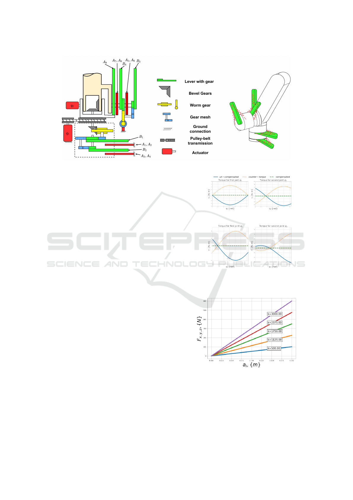
Figure 6: A schematic representation of system assembly.
pure application of the counter-balancing torque on
the intended joint and blocks any reverse torque from
displacing other joints. It acts as a one-way gate to
both motion and torque. This allows mechanical po-
sition feedback from other joints to the compensator
of a certain joint while these joints will not be affected
by the counter-balancing torque produced by this cer-
tain compensator. Other mechanical components are
introduced to realize correct motion ratios.
6 RESULTS
Two main scenarios were tested in simulation. The
first case is when q
1
was given a constant arbitrary
value π/4 while q
2
is spanning between [0, π]. In the
second case, it is the reverse of the first case. Link
length were assigned the values l
1
= l
2
= 500mm. The
value of distances [b
1
,...,b
5
] are assigned a constant
value of 250 mm. Span distance of [a
1
,...,a
9
] is as-
signed to be [0 : 100] mm. An external force of value
F = [100,50,80]
T
(N) is applied on the tip of the sec-
ond link. . Values of spring constants k
i
are calculated
using eqs. (23),(24) and (26). Simulation results show
that we can achieve complete compensation of exter-
nal force in any configuration around the work space.
Figure 7 shows the simulation’s results.
The selection of spring constants can be adjusted
provided the range of external force acting on the end
effector. It is more practical to select the design pa-
rameters of a robotic system according to the intended
payload for this system. Selecting the range of pay-
load and range of length a
j
as design parameters can
help with choosing the proper value of the spring con-
stant. Figure 8 shows different ranges of force com-
ponents that the system can compensate for with dif-
ferent values of k
i
provided the range of distance a
j
.
(a) q
1
= π/4 and q
2
spans [0 : π].
(b) q
2
= π/4 and q
1
spans [0 : π].
Figure 7: Torque of the 2-DoF manipulator with the pro-
posed force compensator.
Figure 8: Range of force compensation for different values
of k with certain range of distance a.
7 CONCLUSION
This paper proposes a preliminary concept for an
adaptive external force compensator in which a com-
ICINCO 2022 - 19th International Conference on Informatics in Control, Automation and Robotics
506

bination of springs is integrated. Springs’ fixation
points can be adjusted to produce a counter-torque
that can statically balance a range of applied exter-
nal forces. The design of this compensator shows that
torque due to payload can be decoupled and compen-
sated with a combination of linear springs. Variation
of payload can be compensated by adjusting the dis-
tance of one of the springs’ fixation points. The ratio
between the range of the payload and the distance that
can be spanned by the fixation point can determine
the value of the spring coefficient. The paper presents
the use of the compensator with a 2-DoF manipula-
tor. The simulation shows that a complete compen-
sation of constant payload can be achieved around the
whole workspace. The adaptation feature allows com-
plete compensation in case the payload has changed.
The design of this system is very complex yet, possi-
ble. This system can be very useful in repetitive tasks
with constant payload while having the advantage of
readjusting for different tasks with different payloads.
The advantage of this system is that it reduces energy
consumed to support payload as the robot’s actuators
need only to support dynamic torques.
In the future, it will be necessary to use this com-
pensator with manipulators with more than 2-DoF and
to test it on real hardware.
ACKNOWLEDGEMENTS
This work was supported by Russian Scientific Foun-
dation (Project number 22-41-02006).
REFERENCES
Agrawal, S. K. and Fattah, A. (2004). Gravity-balancing of
spatial robotic manipulators. volume 39, pages 1331–
1344. Elsevier Ltd.
Arakelian, V. (2016). Gravity compensation in robotics. Ad-
vanced Robotics, 30:79–96.
Arakelian, V., Dahan, M., and Smith, M. (2000). A histor-
ical review of the evolution of the theory on balanc-
ing of mechanisms. In Ceccarelli, M., editor, Interna-
tional Symposium on History of Machines and Mecha-
nisms Proceedings HMM 2000, pages 291–300, Dor-
drecht. Springer Netherlands.
Cho, C. and Kang, S. (2014). Design of a static balanc-
ing mechanism for a serial manipulator with an un-
constrained joint space using one-dof gravity compen-
sators. IEEE Transactions on Robotics, 30:421–431.
Cho, C., Lee, W., Lee, J., and Kang, S. (2012). A 2-dof
gravity compensator with bevel gears. Journal of Me-
chanical Science and Technology, 26:2913–2919.
Chung, D. G., Hwang, M., Won, J., and Kwon, D.-S.
(2016). Gravity compensation mechanism for roll-
pitch rotation of a robotic arm. In 2016 IEEE/RSJ In-
ternational Conference on Intelligent Robots and Sys-
tems (IROS), pages 338–343.
Gopalswamy, A., Gupta, P., and Vidyasagar, M. (1992). A
new parallelogram linkage configuration for gravity
compensation using torsional springs. In Proceedings
1992 IEEE International Conference on Robotics and
Automation, pages 664–665. IEEE Computer Society.
Jhuang, C. S., Kao, Y. Y., and Chen, D. Z. (2018). Design of
one dof closed-loop statically balanced planar linkage
with link-collinear spring arrangement. Mechanism
and Machine Theory, 130:301–312.
Kim, H. S., Min, J. K., and Song, J. B. (2016). Multiple-
degree-of-freedom counterbalance robot arm based on
slider-crank mechanism and bevel gear units. IEEE
Transactions on Robotics, 32:230–235.
Kim, H.-S. and Song, J.-B. (2014). Multi-dof counterbal-
ance mechanism for a service robot arm. IEEE/ASME
Transactions on Mechatronics, 19:1756–1763.
Kim, S. H. and Cho, C. H. (2017). Static balancer of
a 4-dof manipulator with multi-dof gravity compen-
sators. Journal of Mechanical Science and Technol-
ogy, 31:4875–4885.
Klimchik, A. and Pashkevich, A. (2022). Stiffness Model-
ing for Gravity Compensators, pages 27–71. Springer
International Publishing, Cham.
Klimchik, A., Pashkevich, A., Caro, S., and Furet, B.
(2017). Calibration of industrial robots with pneu-
matic gravity compensators. In 2017 IEEE Inter-
national Conference on Advanced Intelligent Mecha-
tronics (AIM), pages 285–290. IEEE.
Klimchik, A., Wu, Y., Dumas, C., Caro, S., Furet, B., and
Pashkevich, A. (2013). Identification of geometrical
and elastostatic parameters of heavy industrial robots.
In 2013 IEEE International Conference on Robotics
and Automation, pages 3707–3714. IEEE.
Koser, K. (2009). A cam mechanism for gravity-balancing.
Mechanics Research Communications, 36:523–530.
Lin, P. Y., Shieh, W. B., and Chen, D. Z. (2010). Design of
a gravity-balanced general spatial serial-type manipu-
lator. Journal of Mechanisms and Robotics, 2.
Lin, P. Y., Shieh, W. B., and Chen, D. Z. (2012). Design
of statically balanced planar articulated manipulators
with spring suspension.
Morita, T., Kuribara, F., Shiozawa, Y., and Sugano, S.
(2003). A novel mechanism design for gravity com-
pensation in three dimensional space. In Proceed-
ings 2003 IEEE/ASME International Conference on
Advanced Intelligent Mechatronics (AIM 2003), vol-
ume 1, pages 163–168. IEEE.
Nakayama, T., Araki, Y., and Fujimoto, H. (2009). A
new gravity compensation mechanism for lower limb
rehabilitation. In 2009 International Conference on
Mechatronics and Automation, pages 943–948. IEEE.
External Force Adaptive Compensator for Serial Manipulators
507
