
Extending LoRaEnergySim Simulator to Support Interference
Management under Multi-Gateway IoT Scenarios
Daniele Stumpo, Floriano De Rango and Francesco Buffone
DIMES, Universit
`
a della Calabria, Via P. Bucci, Arcavacata di Rende(CS), Italy
Keywords:
Simulator, LoRa, LoRaEnergySim, Multi-Gateway, LPWAN.
Abstract:
Internet of Things (IoT) is gaining more impact on our lives and has been increasingly used. It allows several
wireless devices to be connected, and their distance can range from a few inches to many miles. New IoT
technologies such as LoRa are emerging allowing energy efficient wireless communication over exceptionally
long distances. So, it is particularly important to evaluate its performance through simulations. At this purpose,
it is possible to find several tools and simulators for LoRa technology. All of them present distinctive features
and are written with different programming languages with the possibility to enable and disable different
features. In this paper it is analysed in detail the Simulator LoRaEnergySim, which allows the creation of
a network with only one Gateway (GTW). In addition, the simulator is extended considering the case of
Multi-GTW presence with very high IoT node density and considering all interference aspects that can be
related to this new scenario. Besides, the extended simulator, considers now the imperfect orthogonality of
the Spreading Factor (SF) not fully supported in the previous simulator version with the aim to consider more
realistic simulations.
1 INTRODUCTION
In recent years, the IoT paradigm has gaining a lot
of attention, with a continuous rise of new emerg-
ing technologies, especially in the LPWAN domain.
One of these is LoRa, whose characteristics are a
wide range of coverage (even up to 10km), a low bi-
trate, sporadic communication, low duty cycle (DC)
and high scalability. The most important feature is
the low energy consumption; this due to the Chirp
Spread Spectrum (CSS) and the low sensitivity that
has a LoRa receiver. This led the scientific commu-
nity to create new tools and simulators to evaluate the
performance of this technology. Some tools evaluate
performance at physical level, then, there are several
simulators that implement different features, but cur-
rently there is not one that meets all the needs of a
LoRa network; in fact, no simulator implements all
End Device (ED) classes; most of them implement
only class A devices, and only a few of them imple-
ment class C. In addition, there are simulators that al-
low the creation of networks with only one GTW, and
only a few allows Multi-GTW. Moreover, imperfect
orthogonality of the SF or the energy consumption are
not always considered.
Creating a simulator that implements all the features
of communication and network standards would led
to a greater knowledge about the considered technol-
ogy and provide a much more valuable tool for cre-
ating simulations closer to reality. So, the aim of this
paper is the implementation of additional simulation
modules on an open simulator to allow researchers to
test the LoRa technology in a more effective way.
The paper is organized as follows: Lora technology
are presented in section II; some related works are in-
troduced in section III; in section IV LoRaEnergySim
simulator is explained and in section V some exten-
sions in LoRaEnergySim are explained; finally, con-
clusions are summarized in section VI.
Table 1: Table of acronyms.
Terms Acronym
Spreading Factor SF
End Device ED
Gateway GTW
Network Server NS
Application Server AS
Duty Cycle DC
Adaptive Data Rate ADR
Packet pkt
Chirp Spread Spectrum CSS
364
Stumpo, D., De Rango, F. and Buffone, F.
Extending LoRaEnergySim Simulator to Support Interference Management under Multi-Gateway IoT Scenarios.
DOI: 10.5220/0011319600003274
In Proceedings of the 12th International Conference on Simulation and Modeling Methodologies, Technologies and Applications (SIMULTECH 2022), pages 364-371
ISBN: 978-989-758-578-4; ISSN: 2184-2841
Copyright
c
2022 by SCITEPRESS – Science and Technology Publications, Lda. All rights reserved

2 LoRa
LoRa technology is a wireless technology based on
the Industrial-Medical-Scientific (ISM) band, it is
used for applications that need great coverage, low
power consumption and low bitrate. This technol-
ogy is based on CSS, which has been used for sev-
eral years in military field, thanks to the robustness to
interference, but LoRa is the first technology that has
implemented it for commercial use. LoRaWAN was
designed and developed by the LoRa Alliance. The
development started from the bottom in order to opti-
mize Low Power Wide Area Networks (LPWANs),
thus, optimizing battery life, wide coverage range,
scalability, reliability and cost (Farrell, 2018). LoRa
and LoRaWAN terms are used interchangeable but,
actually, they have different meanings:
• When talking about ’LoRa’ it refers to the physi-
cal layer or wireless modulation.
• The term ’LoRaWAN’ refers to the specific proto-
col that was designed based on LoRa technology
by the LoRa Alliance.
The advantages of LoRa are many, but perhaps the
most notable is the wide coverage, in fact, a single
GTW has the ability to cover an entire city or 100km
2
(10km x 10km). Obviously, the coverage area de-
pends a lot on the environment and the various obsta-
cles present in the area. The LoRa link budget is one
of the biggest in comparison with all other standard-
ized communication technologies, in fact it is about
155dB and thanks to this it is possible to have a wide
range of coverage in an environment.This technology
is suitable for LPWANs, so it is not used in applica-
tions where a large amount of data is required, such
as video streaming, but it is mainly used for transfer-
ring data acquired from a sensor or diagnostic infor-
mation related to networked devices and transmitted
infrequently (Zourmand et al., 2019).
2.1 LoRa PHY
LoRa’s physical layer is a proprietary Spread Spec-
trum modulation scheme from Semtech. This scheme
is derived from the CSS modulation; this type of mod-
ulation manages to change the data rate for sensitivity
within a fixed channel bandwidth.
This is possible due the use of orthogonal SFs, which
can affect the data rate. Applying a specific SF, it is
possible to change the data rate influencing the trans-
mission distance or the power. This allows the per-
formance of a network to be optimized at a constant
bandwidth. In addition, Semtech has made only an
implementation of the PHY layer that is independent
from the upper layers; this is a positive factor because
LoRa can coexist and interoperate with existing net-
work architectures. The CSS of LoRa is derived from
Direct Sequence Spread Spectrum (DSSS), in which
the carrier phase of the signal changes according to a
sequence of codes. The signal transmitted by LoRa
occupies a bandwidth typically 125KHz, 250KHz or
500KHz and depending on different geographical re-
gions, a specific frequency must be used. In addition,
radio technologies that transmit in the ISM band have
regulated limitations, in case of LoRa, in the 868MHz
band, used in Europe, there is a DC of 1%, instead as
regards the transmission power you can use a maxi-
mum power of 14 dBm and only for the uplink Chan-
nel it can be used a DC of 10%.
2.2 LoRaWAN-architecture
LoRaWAN is a low-power, wide area networking pro-
tocol built on top of the LoRa radio modulation tech-
nique. It deals with how the network is organized, its
structure, how to access the medium, what to do when
a message does not arrive. Access to the medium
takes place via the ALOHA protocol, i.e., in a com-
pletely random way, which is in fact the main cause
of the limited DC. LoRa architecture (see Fig. 1) has
four main elements: ED, GTW, Network Server (NS)
and Application Server (AS).
ED: can be a sensors that sends the collected data in
Broadcast towards the GTWs or actuators that wait to
receive a specific message. In particular, we can iden-
tify three types of EDs, that differ mainly in how they
receive downlink packet (pkt):
• Class A: it has receiver window only after trans-
mitting a pkt; this type of class must be imple-
mented in all LoRa devices and is the least energy-
consuming class.
• Class B: it has a periodic receiver window that is
synchronized based on a beacon sent by the GTW.
• Class C: it is always listening except when send-
ing a pkt.
Figure 1: LoRa architecture.
Extending LoRaEnergySim Simulator to Support Interference Management under Multi-Gateway IoT Scenarios
365

GTW: Can be defined as a concentrator of informa-
tion, it is connected to each ED of the network and
its main task is to forward the received pkts to the NS
through another technology, such as Ethernet, Cellu-
lar Networks, Wi-Fi etc., In addition a GTW to with-
stand a large network must have good reception ca-
pacity. It has, in fact, antennas with a very low sen-
sitivity, and it must be able to handle a huge number
of messages; this is due to the possibility to simulta-
neously listen on multiple channels thanks to the or-
thogonal codes of the SF and then it must also have
very good computational qualities to be fast to decode
messages that are received with different SF.
NS: is an element that analyses the data coming from
the network. The data/pkts coming from the different
GTWs are filtered, security checks are performed on
the individual pkts received and then if all goes well
the ACKs are generated. If necessary, the NS applies
the Adaptive Data Rate (ADR) to decrease/increase
transmission power or applying different communi-
cation channel through specific SF. If the NS receives
the same pkt from multiple GTWs, it can handle the
duplication and discards each copy. Another task of
the NS, which is also the only element that can define
from whom the data arrives, can check if the received
data is destined for a specific AS and forwards to it.
AS: has the task of processing application-specific
data messages received from the EDs. It also gen-
erates all downlink payloads of the application layer
and sends them to the EDs connected through the NS.
A LoRaWAN network can have more than one AS.
3 RELATED WORKS
The simulation of LoRa networks is particularly im-
portant because it can be used for designing and eval-
uating LoRa-based applications without the need of
expensive deployments. Choosing the right system
parameters such as the SF can improve the power con-
sumption of wireless devices which is the main chal-
lenge in LoRa, as well as in IoT (Bouras et al., 2020).
Moreover, using optimized parameters can improve
several network performances as well as energy con-
sumption. Therefore, to extend the network lifetime
the most important goal is to make sure that as less
collisions as possible occur and that the pkts arrive
with enough power towards the Base Station. Thus,
pkts can be correctly interpreted and that there will
be no need to retransmit them wasting energy. This
will be possible by choosing the right combination of
SF, frequency and bandwidth. This will reduce the
transmission time, increase the data rate and already
improve the energy consumption of IoT devices.
3.1 Existing simulators
Currently, it is possible to find several LoRa simu-
lators online, using different programming languages
but also implementing various parts of the standard.
The main ones are: FLoRa (FLoRa, nd) (Slab-
icki et al., 2018); PhySimulator (PhySimulator,
nd); LoRaWAN Module for ns-3 (Reynders et al.,
2018); LoRaSim (LoRaSim, 2017); LoRaFREE
(Abdelfadeel et al., 2020); LoRaWAN simulator
(Marini et al., 2021); LoRaEnergySim (LoRaEner-
gySim, nd).
3.1.1 FLoRa
FLoRa is a simulation framework that uses the OM-
Net++ discrete event simulator; it is based on the
Framework of INET and is written in C++. It en-
ables to create LoRa-ED, GTWs and a NS. In addi-
tion, its modules aim to simulate the physical layer
and the LoRaWAN MAC protocol. It also provides
an excellent graphical interface. It offers an accu-
rate model for the LoRa PHY layer and also provides
statistics about the network power consumption. It
also gives the option to simulate a network with 1 or
more GTWs (Slabicki et al., 2018).
3.1.2 PhySimulator
This simulator is written in MATLAB, but it imple-
ments only the link level of LoRa. Through this sim-
ulator it is not possible to build a network of LoRa,
but its purpose is only to evaluate the reception of two
overlapping and interfering LoRa transmissions that
have been modulated with different SF. In each exe-
cution, a reference frame modulated with a reference
SF
ref
is added with a random number of interfering
symbols modulated with a different SF
int
. The resul-
tant overlapped signal is demodulated in absence of
noise, assuming a perfect receiver synchronization.
Finally, it will be generated figures where you can see
the interference generated due to non-orthogonality of
SF, and, moreover, Packet Error Rate (PER), Symbol
Error Rate (SER) and Bit Error Rate (BER) of the ex-
periment.
3.1.3 LoRaWAN Module for NS-3
This is not a simulator itself, but it is a module to be
integrated in NS-3. The module is written in C++ and
Python and the implementation is compliant with Lo-
RaWAN 1.0 class A. This last one is the most energy
efficient of the LoRa devices. Also, in addition to the
two lower layers, PHY and MAC, the Transport layer
and Application layer have been implemented so that
SIMULTECH 2022 - 12th International Conference on Simulation and Modeling Methodologies, Technologies and Applications
366

as many parameters as possible can be configured.
In order to keep track of the energy consumption an
additional class has been implemented, whose name
is LoRaRadioEnergyModel (Reynders et al., 2018).
3.1.4 LoRaSim
LoRaSim is a discrete event simulator written in
python2.7 that uses several libraries, such as SimPy,
which is a library that provides an environment for
making simulations. This simulator offers the chance
to run four different network configurations. Two of
them are done with a single GTW and two with up
to four GTWs. It is possible to use either omnidi-
rectional or directional antenna modules. Then, it is
allowed to set different parameters as the number of
EDs, the number of GTWs, the distance between two
GTWs, the number of LoRa networks and the simula-
tion time. Other two features that can be set is the gen-
eration of a graph that shows the configuration of the
network and how to control the collisions, in a sim-
plified way, then controlling only SF, Freq and time
or in a complete way also controlling the power and
then using the capture effect (Bouras et al., 2020) (Bor
et al., 2016). The log-distance path loss model is im-
plemented as radio propagation model. This simula-
tor does not track the energy consumption of individ-
ual devices, but the energy consumption of the entire
network, so deriving the amount of energy spent by
individual devices using different SFs would be diffi-
cult. In order to start a simulation, one has to create
a configuration file, in which the different simulation
parameters are specified, such as, the number of EDs,
how the pkt generation takes place, the pkt size, etc.
Regarding the generation of pkts, it can be set in three
different ways, i. e., periodic generation, random gen-
eration, or following a exponential model. At the end
of the simulation there will be created a file in which
the PDR for each application and the total energy con-
sumption will be reported.
3.1.5 LoRaFREE
In this simulator, besides the uplink communication
(ED-GTW), the downlink communication has also
been implemented (to respond with an acknowledge-
ment (ACK) from the GTW to the ED). In addition to
this, it also implements imperfect orthogonality of the
SF. The simulator allows only periodic communica-
tion by the EDs and the propagation model used is the
log-distance path loss model as in LoRaSim; more-
over, in comparison to LoRaSim, the energy con-
sumption module has been extended, as it also con-
siders the energy consumed when receiving feedback
from the GTW to the ED (Abdelfadeel et al., 2020).
3.1.6 LoRaWAN Simulator
LoRaWAN simulator is entirely written in MatLab
and implements a complete LoRa transceiver for the
PHY layer which is responsible for signal generation,
modulation and demodulation. A MAC layer that
is responsible for multiple channel access and takes
care of mutual interference and supporting more than
one GTW is also implemented. The simulator sup-
ports a number of features, such as both uplink and
downlink communications, imperfect SF orthogonal-
ity, capture effect, both uplink and downlink interfer-
ence, DC limitations, A and C class devices. At the
end of the simulation, there are several performance
metrics such as the delivery rate for both uplink and
downlink and the energy consumption values for each
device and for the entire network (Marini et al., 2021)
3.1.7 LoRaEnergySim
LoRaEnergySim is a simulator developed in Python3
and uses the SimPy library, and it is a cross-layer sim-
ulation framework to analyse the energy consump-
tion of devices in a realistic way. In addition, the
ADR mechanism is implemented in the simulator
and downlink messages have also been implemented.
This has a significant impact on the number of data
extraction rate. The payload size, transmission fre-
quency can be set easily. Power consumption will be
done and any state changes of the ED, such as, idle,
active, sleep are represented (Callebaut et al., 2019).
4 LoRaEnergySim
After analyzing all the different simulators that were
found online, it is chosen to work with the Lo-
RaEnergySim simulator (the code can be found in
https://github.com/GillesC/LoRaEnergySim). This
simulator is chosen because:
• It uses Python as its Programming languages, with
the following benefits:
– Portable, therefore it is easy to install on differ-
ent platforms such as Linux, Windows, etc
– Easy to use because the syntax and the differ-
ent modules and functions that are already in-
cluded in the language are consistent, intuitive,
and easy to learn.
– Rich in Libraries, so if it is necessary to imple-
ment new objects it can always take a look on
the Python Package Index.
– Efficient, so it guarantees high performance.
• It has already implemented a module on the en-
ergy consumption of the single device.
Extending LoRaEnergySim Simulator to Support Interference Management under Multi-Gateway IoT Scenarios
367
• Uses a log-distance path loss model, that can
be easily changed by modifying the simulation
model.
• It has an easily modifiable structure because it is
structured in different classes.
The simulator provides a generic framework for eval-
uating and co-optimizing PHY and MAC parameters
under realistic network conditions. Each component
of the simulator is built on the basis of individual
components. It works in a very simple way: there
is a class A ED that sends its pkts to the AirInterface;
over this interface some models for the signal prop-
agation were implemented and it is possible to eval-
uate the SNR and the collision; if the pkt passes all
the physical requirements it arrives at the GTW that
processes it, but only if it arrives with enough power
to be interpreted. After this step, if the ED waits for a
confirmation, the GTW will send an ACK message to
confirm the received message.
4.1 Simulator Structure
The Simulator-Structure is summarized in Figure 2.
4.1.1 LoRaWAN ED Class A
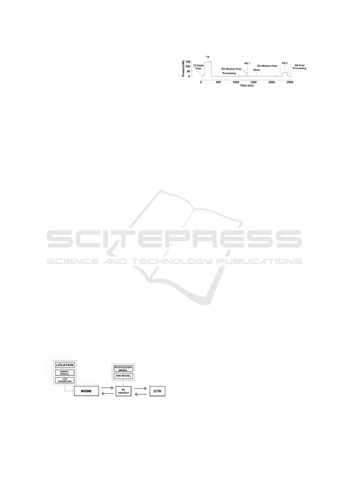
Each ED is characterized by an energy profile, a set
of LoRa parameters, such as SF and frequency, and a
location, given by the class Location. The energy pro-
file used in the simulator is as in the Figure 3 (Calle-
baut et al., 2019).
From the figure it can be seen that there are mainly
three peaks of energy consumption. The first corre-
sponds to the transmission of a pkt, which has a du-
ration equal to the Time on Air (ToA). The other two
peaks correspond to the two reception windows, the
first, RX1, is when the ED listens on the same fre-
quency of the uplink message for a duration that de-
pends on the SF used during the transmission of the
pkt, while in the second, RX2, it listens on the down-
link frequency. If the message should be received al-
ready in the first reception window, the ED will not
use the second slot.
Figure 2: LoRaEnergySim Structure.
Figure 3: Energy Profile of a LoRaWAN ED Class A.
4.1.2 AirInterface
This module has mainly three tasks: calculating the
path loss, translating the received signal strength
(RSSI) into an SNR value and finally determining a
pkt collision. These tasks are managed through:
• Propagation Model: uses the log-distance path
loss model with shadowing, and it is used to
model the signal when it is transmitted from the
ED to the GTW.
• SNR model: adds background noise to the trans-
mitted signal.
• Collision Detection Task: pkts collide if they will
be transmitted with same frequency, same SF, are
time-overlapped. Finally, the power difference
between the two pkts is evaluated and if the dif-
ference is less than power threshold (e.g. 6dB)
pkts collide, otherwise the most power pkt will be
correctly interpreted.
4.1.3 Gateway
The GTW implemented on the Simulator is capable of
simultaneously reading 8 pkts with different parame-
ters (SF and Freq). Furthermore, the signal must not
have collided, and the signal strength must be higher
than the Antenna sensitivity. If a communication has
been set up where messages must be acknowledged,
then the GTW itself creates an ACK message. Cur-
rently it is assumed that the downlink message always
reaches the ED as the GTWs have a higher allowed
transmission power. Also, there is the possibility of
only creating networks with a single GTW.
5 Extended LoRaEnergySim
Based on the LoRaEnergySim Simulator, new exten-
sions that allow the simulator to increase its flexibility,
therefore increasing the number of simulation scenar-
ios have been led out. Another important thing is the
introduction of the imperfect orthogonality of the SFs.
5.1 Changes Made to Simulator
In order to bring the simulator closer to the real world,
several changes have been made:
SIMULTECH 2022 - 12th International Conference on Simulation and Modeling Methodologies, Technologies and Applications
368
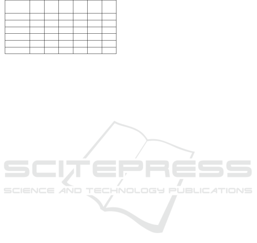
Table 2: SIR Threshold between SFs.
SF
int
→ 7 8 9 10 11 12
SF
ref
↓
7 1 -8 -9 -9 -9 -9
8 -11 1 -11 -12 -13 -13
9 -15 -13 1 -13 -14 -15
10 -19 -18 -17 1 -17 -18
11 -22 -22 -21 -20 1 -20
12 -25 -25 -25 -24 -23 1
• From Single-GTW to Multi-GTW.
• ACK Management with ideal NS.
• Different pkt rates on different EDs.
• Piggybacking on ACK, to communicate parame-
ters to ED, like ADR.
• Display the network topology based on parame-
ters at the end of the simulation.
• Addition of new stats such as pkts latency, col-
lided pkts, the number of totals sent and created
pkts and so on.
• New parameters for Antenna Sensitivity (Antenna
Sensitivity, 2019)
• Introduction of imperfect orthogonality (Croce
et al., 2018)
5.1.1 From Single-gateway to Multi-gateway
The first change was the extension into a Multi-GTW
scenario, supporting the creation of a network with
1 to 9 GTWs. They were positioned more or less
balanced and equidistant, but could be repositioned
differently easily. The important consideration at this
stage was how to handle the interference created on all
GTWs. So, for each GTW, it will be created a propri-
etary AirInterface where the communication channel
of the single GTW is managed. However, it is very
important that every time an ED wants to communi-
cate a pkt, it must insert the pkt on all the AirInter-
faces, so it is possible to calculate on all the various
GTWs how the pkt arrives, if it does not collide and
if it arrives with enough power. In addition, as the
LoRa standard is defined, the pkt can be read by sev-
eral GTWs at the same time, since the communication
is in Broadcast.
5.1.2 Imperfect SF-orthogonality
Another added feature is the control of imperfect SF
orthogonality, in fact, collisions between pkts modu-
lated with different SFs can also occur if the received
interference power is strong enough. This contradicts
the common belief that SFs can be considered orthog-
onal. The results of (Croce et al., 2018) show that
intra-SF collisions are indeed a problem in LoRa net-
works. Also, Table 2 was extracted from (Croce et al.,
2018), and inserted into the simulator.
Originally, the simulator checked for four conditions
to see if there was a collision, as mentioned earlier.
After applying this upgrade, the behavior of the simu-
lator now is firstly the check of two conditions: if two
EDs use the same frequency and if there is a temporal
overlap in the communication; then it will be consid-
ered the Table 2, it will check simultaneously SF and
power level.
To make clearer the whole behavior an example is as
follows: let us suppose there are two pkts in the com-
munication channel with the same frequency and a
time overlap, with the following SF and power val-
ues:
• PKT
1
→ SF=8, P
TX
=-102dBm
• PKT
2
→ SF=12, P
TX
=-129dBm
Now it will be seen what happens when these 2
pkts arrive at the GTW. Starting to verify PKT
1
,
from table 2 we taking to account the cell referring
to SF
ref
=8 and SF
int
=12, which indicates a power
threshold of 13dB. This means that if the interfering
PKT
2
presents a power greater than 13dB compared
to PKT
1
, then the last one can not be interpreted. Here
below we can see how it works:
• SF
REF
→ 8, SF
INT
→ 12
Inter f erence > −13 > NoInter f erence
P
Tx(SF
REF
)
− P
Tx(SF
INT
)
= −102 − (−129) = +27
The calculation just performed implies that PKT
1
can
be interpreted. The same process has to be taken into
account for PKT
2
. Referring again to table 2, it must
be considered SF
ref
=12 and SF
int
=8. Now, if the in-
terfering PKT
2
presents a power greater then 25dB
compared to PKT
1
, then the last one can not be inter-
preted, in fact, in this case the difference is:
• SF
REF
→ 12, SF
INT
→ 8
Inter f erence > −25 > NoInter f erence
P
Tx(SF
REF
)
− P
Tx(SF
INT
)
= −129 − (−102) = −27
Since in this case the interfering signal is 27dB greater
than the referenced Signal, it can be concluded that
PKT
2
can not be interpreted.
5.2 ACK Management with NS
Each time an ED must receive an ACK it has been as-
sumed that it can only be sent by the nearest GTW;
if the pkt does not arrive at the nearest GTW, because
it experienced a collision or because it arrived at the
nearest GTW with too low power, but the pkt arrives
at a more distant and visible GTWs, then the NS will
Extending LoRaEnergySim Simulator to Support Interference Management under Multi-Gateway IoT Scenarios
369
inform all GTW about the packer reception and send-
ing back the ACK to the sender ED.
To manage this, it is necessary to analyse what is hap-
pening with the pkt on all the AirInterfaces, check-
ing for interference with other pkts in the communi-
cation channel and analysing whether there are any
collisions and how strongly the pkt reaches the vari-
ous GTWs. After that, it is checked whether the com-
munication with the closest GTW was successful and
if it was, then the GTW will directly send the ACK to
the ED in the correct reception window, ignoring what
happens on the other GTWs; thus, excluding pkt du-
plication, on the other hand, if the closest GTW does
not receive the pkt, then it will be checked on the other
GTWs and it will be seen if, at least one of them, has
received it; if this is the case, then, it will be commu-
nicated to the closest GTW of the ED that must com-
municate an ACK to the ED; instead, if even the other
GTWs do not receive it, then the communication has
failed and a retransmission must be attempted. More-
over, when sending the ACK, there is the possibility
of inserting information to be given to the EDs, so as
in the case of the ADR.
5.3 Other Simulator Changes
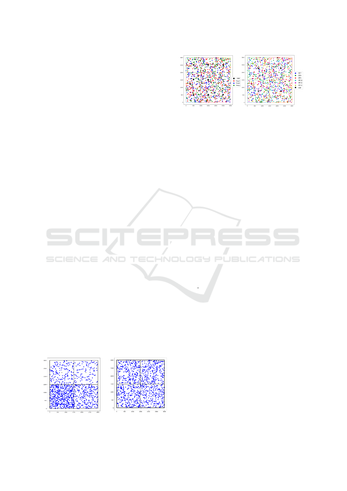
Considering that in a network it is possible that there
are different types of devices related to different IoT
applications, it is provided now in the simulator the
possibility to select for each ED different pkts rate. It
can be created denser and sparser zones supporting
homogeneous and heterogeneous distributions; this
feature has been introduced to consider GTWs under
different traffic loads. In figure 4 it is possible to see
as the additional behaviors of heterogeneous ED den-
sity is supported.
There is now also the possibility of inserting some in-
formation on the acknowledgment pkt, so in piggy-
backing as in the case of ADR; of course, there are
limited resources so there is no chance to put large
information, but it is possible to include some param-
eters such as SF or transmission power or the number
of pkts that a ED must transmit in ACK.
At the end of the simulation now, activating a func-
Figure 4: Unbalanced network vs. Balanced Network.
Figure 5: Coloured ED according to Frequency or SF.
tion, there is the possibility to show a plot, where
there will be inserted GTW and EDs and these can
be distinguished through colors. In figure5 are show
colors applied to ED with different SFs or different
frequencies. In the simulator another important fea-
ture that has been added is the collection of new in-
formation such as the energy consumed by each ED
and the whole network, pkts latency, collided pkts and
the number of totals sent and created pkts. Moreover,
it will be created a file containing besides those previ-
ously mentioned some new statistics, like:
• Weak pkts, collisions due to imperfect orthogo-
nality, times that it was not possible to receive an
ACK because of DC limitation and retransmitted
pkts;
• How many times there have been pkts that have
completely failed the communication; therefore,
they have exceeded the maximum retransmissions
value:
• How many collisions, distinguishing if they hap-
pened on the same SF or between different SF, on
the single GTWs;
• How many times each GTW has reached the
DC Limit and has not been able to send an ACK;
• What happens when a pkt does not arrive towards
the nearest GTW but towards other GTWs?
These statistics are supported also on the single ED,
so it can be seen how many times it was used a spe-
cific SF, how many times a specific Frequency, and
then will be computed the average value of the afore-
mentioned metrics for both the single and the whole
network.
5.4 Final Structure of the Simulator
The new structure of the simulator can be seen in fig-
ure 6. Every ED has its own parameters like the Lo-
cation, the Energy Profile and the LoRa Parameters;
moreover, every ED, to communicate with the GTW,
uses the AirInterface, and every time that a ED will
send a pkt, a link to each AirInterface is provided
to account for the total interference introduced in the
SIMULTECH 2022 - 12th International Conference on Simulation and Modeling Methodologies, Technologies and Applications
370
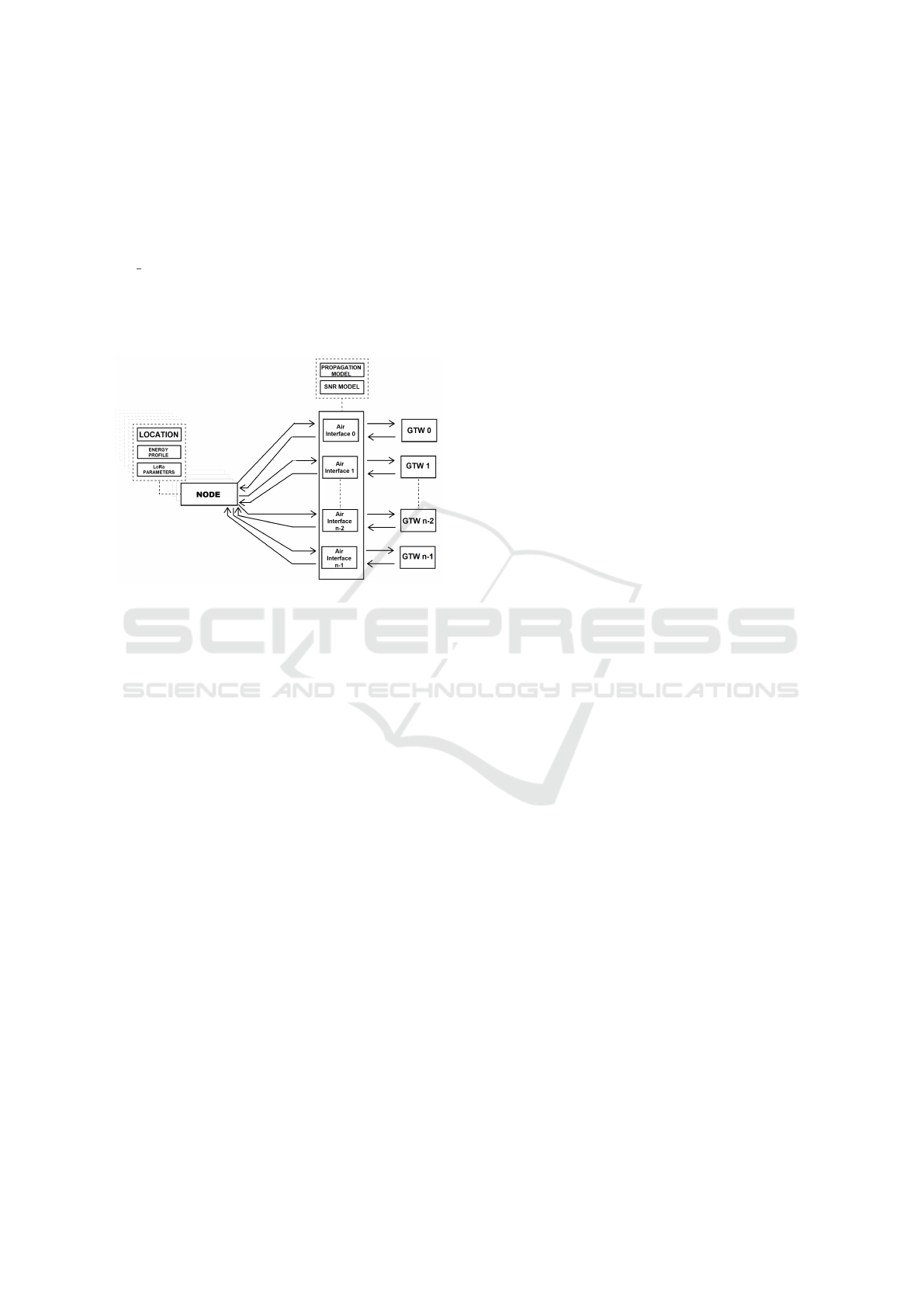
network. Every AirInterface compute if the pkts col-
lided or not and if they arrive with enough power to
the GTW. So, its task is to virtualize the communi-
cation channel of a GTW, then the NS is created in
an abstract mode, and it decides when a GTW must
send an ACK and when every GTW must respect the
DC Limit before it will send the ACK message.
Finally it worth noting that upon this kind of simula-
tor could be applied any kind of suited protocol and
an example of this is presented in (De Rango et al.,
2021)
Figure 6: Final Structure of LoRaEnergySim.
6 CONCLUSIONS
The aim of this paper is to provide an overview about
LoRa and the existing Simulator engines, which al-
low to evaluate the performance of LoRa network
in different ways. The overviewed Simulators are
Flora, PhySimulator, LoRaWAN Module for NS-3,
LoRaSim, LoRaFREE & LoRaEnergySim. We fo-
cused our attention on the last one providing a set of
custom modifications to extend the basic behaviour
implemented by LoRaEnergySim. The most impor-
tance additional features introduced in the simulator
are: Multi-GTW-Extension with interference man-
agement, the imperfect SFs orthogonality, ACK man-
agement and new statistics to improve the network
analysis.
REFERENCES
Abdelfadeel, K. Q., Zorbas, D., Cionca, V., and Pesch, D.
(2020). Free - fine-grained scheduling for reliable and
energy-efficient data collection in lorawan. IEEE In-
ternet of Things Journal, 7(1):669–683.
Antenna Sensitivity (2019). Understanding adr. https://lora-
developers.semtech.com/documentation/tech-papers-
and-guides/understanding-adr.
Bor, M. C., Roedig, U., Voigt, T., and Alonso, J. M. (2016).
Do lora low-power wide-area networks scale? In Pro-
ceedings of the 19th ACM International Conference
on Modeling, Analysis and Simulation of Wireless and
Mobile Systems, MSWiM ’16, page 59–67, New York,
NY, USA. Association for Computing Machinery.
Bouras, C., Gkamas, A., Katsampiris Salgado, S. A., and
Kokkinos, V. (2020). Comparison of lora simula-
tion environments. In Barolli, L., Hellinckx, P., and
Enokido, T., editors, Advances on Broad-Band Wire-
less Computing, Communication and Applications,
pages 374–385, Cham. Springer International Pub-
lishing.
Callebaut, G., Ottoy, G., and van der Perre, L. (2019).
Cross-layer framework and optimization for efficient
use of the energy budget of iot nodes. In 2019
IEEE Wireless Communications and Networking Con-
ference (WCNC), pages 1–6.
Croce, D., Gucciardo, M., Mangione, S., Santaromita, G.,
and Tinnirello, I. (2018). Impact of lora imperfect
orthogonality: Analysis of link-level performance.
IEEE Communications Letters, 22(4):796–799.
De Rango, F., Lipari, A., Stumpo, D., and Iera, A. (2021).
Dynamic switching in lorawan under multiple gate-
ways and heavy traffic load. In 2021 IEEE Global
Communications Conference (GLOBECOM), pages
1–6.
Farrell, S. (2018). Low-power wide area network (lpwan)
overview. Rfc, RFC Editor.
FLoRa (n.d.). Home — flora - a framework for lora simu-
lations. https://flora.aalto.fi/.
LoRaEnergySim (n.d.). Github - gillesc/loraenergysim:
Lora network simulator to monitor energy consump-
tion. https://github.com/GillesC/LoRaEnergySim.
LoRaSim (2017). Lorasim.
https://www.lancaster.ac.uk/scc/sites/lora/lorasim.html.
Marini, R., Mikhaylov, K., Pasolini, G., and Buratti, C.
(2021). Lorawansim: A flexible simulator for lorawan
networks. Sensors, 21(3).
PhySimulator (n.d.). Lora – simulation & experimentation
tools for lora networks. http://lora.tti.unipa.it/.
Reynders, B., Wang, Q., and Pollin, S. (2018). A lorawan
module for ns-3: Implementation and evaluation. In
Proceedings of the 10th Workshop on Ns-3, WNS3
’18, page 61–68, New York, NY, USA. Association
for Computing Machinery.
Slabicki, M., Premsankar, G., and Di Francesco, M. (2018).
Adaptive configuration of lora networks for dense iot
deployments. In NOMS 2018 - 2018 IEEE/IFIP Net-
work Operations and Management Symposium, pages
1–9.
Zourmand, A., Kun Hing, A. L., Wai Hung, C., and Ab-
dulRehman, M. (2019). Internet of things (iot) us-
ing lora technology. In 2019 IEEE International Con-
ference on Automatic Control and Intelligent Systems
(I2CACIS), pages 324–330.
Extending LoRaEnergySim Simulator to Support Interference Management under Multi-Gateway IoT Scenarios
371
