The FischerTwin: An Experimentable Digital Twin Case Study
Alexander Atanasyan
a
, Felix Casser
b
, Arthur Wahl
c
and Juergen Rossmann
Institute for Man-Machine Interaction, RWTH Aachen University, Ahornstr. 55, Aachen, Germany
Keywords:
Experimentable Digital Twins, Digital Twin, Robotics, Fischertechnik, MBSE, System Life Cycle.
Abstract:
Digital Twins are a rapidly maturing approach of transferring real assets into the digital domain. Experi-
mentable Digital Twins (EDT) allow to not only visualise a digital model of an asset or display its current
state, but allow to interact with the asset within the digital world - with the EDT behaving exactly like the real
twin given analogous inputs from its (real or digital) environment. We created the FischerTwin, an EDT of a
modular fischertechnik swivel arm robot, as our first demonstrator to enable the principles of the FeDiNAR
project - displaying undesired or dangerous consequences of real actions in augmented reality. This paper
presents the design, development and application of this EDT of a complex cyber-physical system including
the steps a) function definition b) collection of requirements, c) structural design of the EDT, d) Implementa-
tion of its components and the entire robotic system and e) application of the EDT—highlighting its usage in
all relevant product life cycle phases. We thus give answers to system-level questions like How can the EDT
be applied throughout a real asset’s life cycle?, What are necessary components for the usage of an EDT? and
What does the interplay between real and digital twins of a complex cyber-physical system look like?.
1 INTRODUCTION
Current cyber-physical systems (CPS) continuously
grow in complexity, rendering system engineering
ever more difficult, while overall, the speed of tech-
nological progress increases. This requires manufac-
turers to react and integrate innovation in increasingly
shorter time frames to reduce time to market in order
to stay competitive and to plainly allow users to ben-
efit from the state of the art. Such a double require-
ment for fast development applies to both software
and hardware, which, ideally, have to be developed in
parallel. Meanwhile, prototypes are one of the ma-
jor expenses during hardware development. Here, the
current capabilities of simulations are a remedy al-
lowing the testing of components without requiring
physical prototypes. Simulation on a system level,
however, still poses a challenge and necessitates a sys-
tematic way of structuring simulation models.
1.1 Digital Twins
An increasingly common and well-known approach
of digitally representing systems is the digital twin
a
https://orcid.org/0000-0002-7578-1820
b
https://orcid.org/0000-0003-2636-2205
c
https://orcid.org/0000-0001-9357-4705
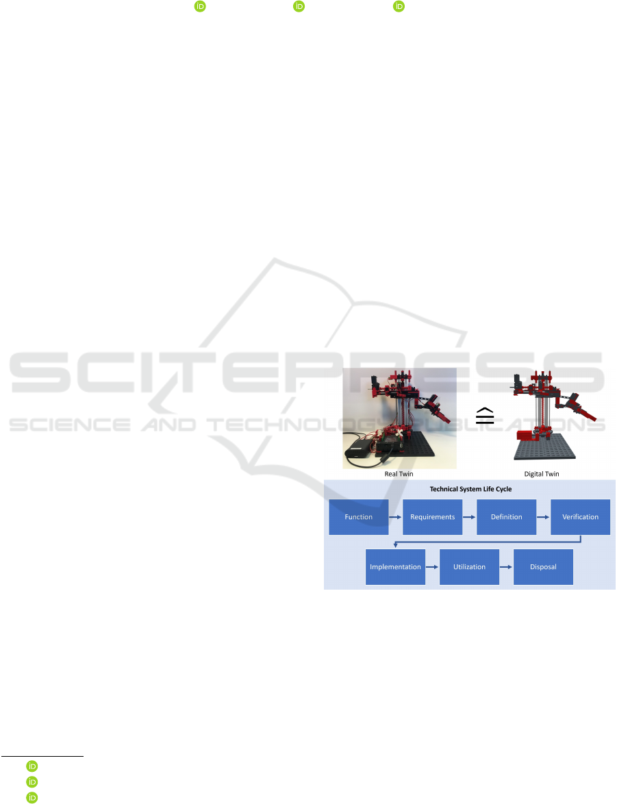
Figure 1: Top: Real twin and its EDT—the FischerTwin—
of our exemplary system. Bottom: System life cycle phases
in which the EDT approach can be used.
(DT) (see Figure 1), a concept introduced about two
decades ago in the aerospace domain (Grieves, 2015),
which has since been applied in numerous different
disciplines and application areas (Tao et al., 2019).
The basic idea is to provide a virtual representa-
tion of a real (technical) system, the real twin, in
terms of structure and behaviour. The latter requires
the use of simulation technology, which delivers all
the necessary methods to represent nearly any aspect
280
Atanasyan, A., Casser, F., Wahl, A. and Rossmann, J.
The FischerTwin: An Experimentable Digital Twin Case Study.
DOI: 10.5220/0011277800003274
In Proceedings of the 12th International Conference on Simulation and Modeling Methodologies, Technologies and Applications (SIMULTECH 2022), pages 280-287
ISBN: 978-989-758-578-4; ISSN: 2184-2841
Copyright
c
2022 by SCITEPRESS – Science and Technology Publications, Lda. All rights reserved

of a complex (technical) system and brings DTs to
life. Combining both, the idea of DTs and modern
methods of simulation, especially form the field of
eRobotics (Kadry and El Hami, 2019), makes DTs
experimentable, yielding the Experimentable Digital
Twin (EDT), as presented in (Schluse et al., 2017).
The structural and behavioural identity with its real
twin allows to co-develop a system’s various hard-
ware and software components independently, to test
and verify their interplay in simulation, to evaluate
the entire system in usage scenarios, but also to ac-
company the real system after its deployment to, e.g.,
either simply supervise and control the current system
state or to augment and systematise its capabilities.
The resulting networks of interacting EDTs model
different application scenarios and are simulated in
Virtual Testbeds (VTBs) in their entirety. VTBs al-
low to simulate networks of interconnected and inter-
acting EDTs (with different levels of detail (LoD)) in
their respective operational environment.
The digital twin is thus a methodology usable
throughout a systems life cycle—a vital instrument
for engineers from conception to testing and a useful
enabling tool during utilisation.
1.2 Motivation: The FeDiNAR Project
In the FeDiNAR research project (Atanasyan et al.,
2020) (German acronym for “making errors didacti-
cally useful with augmented reality”)
1
, we chose to
use EDTs of industrial machines to enable the cre-
ation of a vocational education system. The system
allows trainees working with industrial machines to
experience their errors even if they are dangerous or
economically wasteful. To keep the trainee and the
machine safe at all times, the consequences of critical
errors are only shown in AR. Thus, the created system
shows how EDTs of industrial machines can be used
in the utilisation phase of a machine’s life cycle.
The system’s gradual development required a
demonstrator in order to avoid the risk of damaging
expensive real industrial machines. It should be an
affordable, sufficiently simple and easy-to-handle ma-
chine, but at the same as close as possible to real in-
dustrial machines to facilitate the transfer step from
the demonstrator to the target machines used in the
project. Two particular requirements were the similar-
ity of the interfaces for a) machine-to-machine com-
munication and b) for user interaction.
In this paper, we thus present an EDT-based
life cycle of a complex cyber-physical system us-
ing this demonstrator as an example. We base our
1
https://www.fedinar.rwth-aachen.de/cms/
∼
ezjkt/
FEDINAR/?lidx=1
development on Model-Based Systems Engineering
(MBSE) and highlight the advantages and short-
comings dividing the life cycle into phases akin to
the European Cooperation for Space Standardiza-
tion (ECSS) standard ECSS-M-ST-10C (ECSS Sec-
retariat, 2009). In particular, we derive require-
ments for the EDT based on its desired functions,
present the EDT’s structural design, show how we ap-
proached its implementation and how we used it dur-
ing design and to prepare, test and execute an appli-
cation scenario. Here, we were able to use the EDT as
an interactive functional replacement of the real robot
which allowed us to develop the hybrid real/virtual
FeDiNAR system and learning scenarios even when
the physical asset was unavailable.
This paper continues with an overview of related
work, focusing on DTs and EDTs. In the section
thereafter, we describe the demonstrator system’s de-
sired functionality, particularly listing the require-
ments resulting from the its application. The next
section focuses on the development of the demonstra-
tor system and how we created and used its EDT—
the FischerTwin—to support that process. This is fol-
lowed by a section which describes how we used the
FischerTwin during the development process and the
demonstrator’s application. As usual, we summarise
our work and reflect on it in the conclusion and dis-
cussion section including an outlook on future work.
2 RELATED WORK
Aside from giving an overview of our foundations
and understanding of EDTs, this section provides an
explanation of the used life cycle model and a brief
background of MBSE as the methodology on which
we base the development of our presented use case.
2.1 MBSE
MBSE enables the analysis and modeling of com-
plex interconnected technical systems (such as CPS).
It can be used to systematically determine the require-
ments, structure and behavior of such systems. Thus,
MBSE is the starting point for the modeling of EDT
and is usually based on the UML (OMG UML, 2022)
or SysML specification (OMG SysML, 2022). It
provides the appropriate methodology for the design,
structuring, and formal description of EDTs (Schluse
et al., 2018). This methodology allows identifying
and describing the individual EDTs and their com-
ponents within an interconnected technical system in
necessary detail. During this process, the EDTs can
be specified with respect to their behavior, their prop-
The FischerTwin: An Experimentable Digital Twin Case Study
281
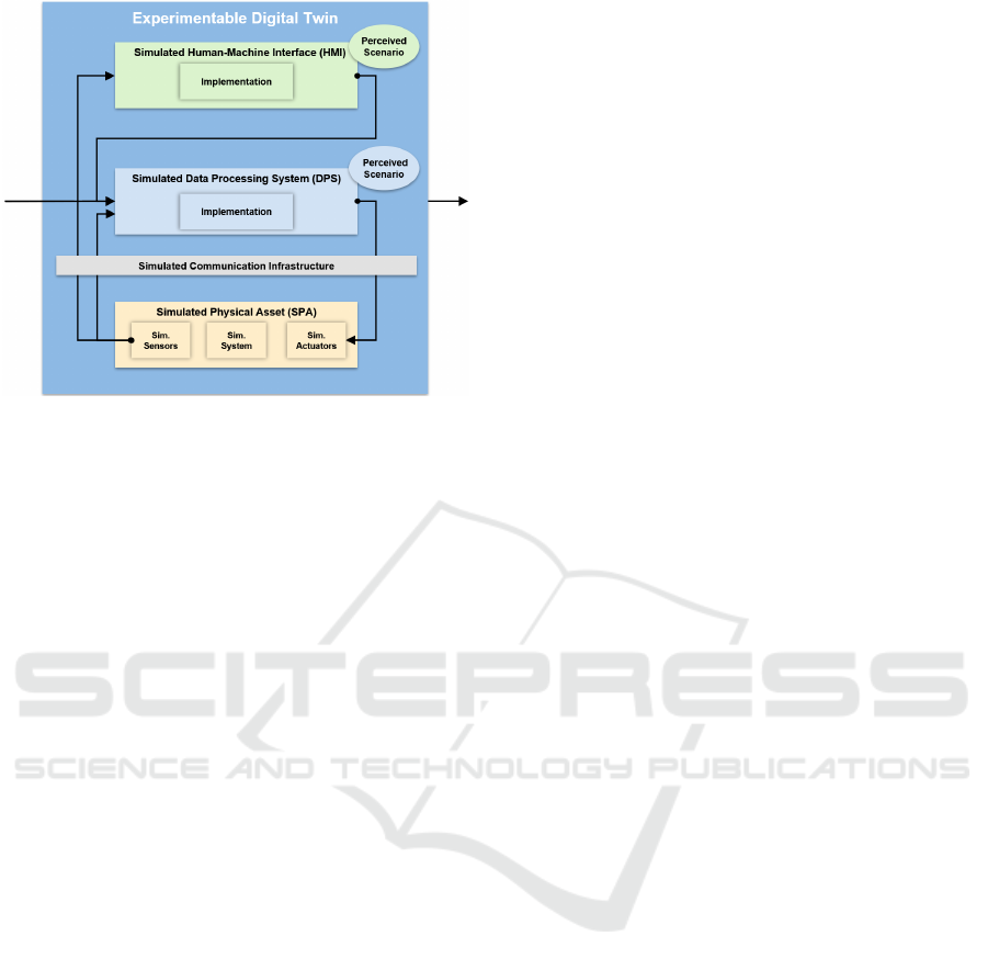
Figure 2: Basic structure of EDTs, figure adapted
from (Schluse et al., 2017).
erties, their parameters, their dependencies or their
functional relationship (e.g. association, aggregation,
composition) to each other. This process can take
place, e.g., in the form of SysML blocks within a
block definition diagram. The definition of ports (in-
teraction points of a system with its environment or
inputs/outputs of a system) and their connections is
used to specify the data flow between the blocks.
Likewise, the approach allows to define requirements
regarding the represented system, which the technical
implementation of the EDT must fulfill, and to spec-
ify test cases for their verification and validation. A
requirements diagram is a concrete tool for this. The
MBSE processes can be applied iteratively to already
identified EDTs and EDT components resulting in the
step-by-step structural composition of an EDT.
2.2 EDTs
EDTs were developed to cope with the increasing
complexity when it comes to the simulation of sys-
tems or entire systems of systems. By introducing
“an intuitively understandable structuring element”
(Schluse et al., 2017), they enable modelling accord-
ing to the physical architecture with focus on the
system structure rather then a tool-centric modeling
based on specific simulation domains or aspects of
the replicated system. Only simulations on the system
level, which are still detailed on component level, are
able to provide the insights necessary to e.g. analyze,
optimise, verify, as well as validate such complex and
interconnected systems. The foundation for such sim-
ulations and, thus, the runtime environment for EDTs
are virtual testbeds (see, e.g., (Osterloh et al., 2018)).
To introduce the concept of an EDT, the DT must
first be defined. The DT denotes “a virtual represen-
tation of a technical asset of a cyber-physical system
with (at least in part) its data and metadata, its func-
tions, its communication capabilities, and the descrip-
tion of its behavior.” (Roßmann and Schluse, 2020).
In contrast to the DT, an EDT replicates not only the
asset or the real part of a cyber-physical, but repli-
cates the cyber-physical system in its entirety. This
also includes all relevant physical interactions with its
environment as well as its internal and external com-
munication capabilities.
An EDT is hierarchically structured and consists
of several different components, see Figure 2. These
EDT components are semantic units which, as part of
an EDT, perform a specific function and, as a whole,
cover the functional scope of the replicated system.
They have their own behavior, which is either mod-
eled directly via suitable simulation models and re-
alised by corresponding simulation algorithms (kine-
matics, rigid body dynamics, sensors, controllers,
Petri nets, etc.), or reproduced by a hierarchically sub-
ordinate EDT. Accordingly, an EDT may contain fur-
ther subordinate EDTs as components and these may
also consist of further EDTs. Following the basic
structure of a CPS, the components of an EDT each
realise one of the following three (technical) subsys-
tems:
• The Simulated Physical Asset (SPA) comprises
the simulated system (e.g. the simulation model
of a machine, a robot, ...) with its sensors (e.g.
cameras, laser scanners, ...) and actuators (e.g.
motors, hydraulic cylinders, ...). It represents the
replicated physical asset.
• The Simulated Data Processing System (DPS)
processes the measured values provided by the
simulated sensors and acts on the SPA via the sim-
ulated actuators to perform specified tasks.
• The Simulated Human-Machine Interface
(HMI) enables the user to monitor and control the
SPA and DPS virtually. Depending on the LoD,
it completely or partially reproduces the various
components of the real HMI.
All components of an EDT as well as the EDT itself
communicate via a simulated communication infras-
tructure, which emulates the communication infras-
tructure of the real CPS and can be connected to it if
required. It includes all the facilities required for the
technical implementation of data exchange between
the EDTs and their components. Data exchange takes
place via ports and their connections. This formalism
enables the exchange of material, energy or informa-
tion between two or more compatible ports. The sim-
ulated communication infrastructure thus describes a
SIMULTECH 2022 - 12th International Conference on Simulation and Modeling Methodologies, Technologies and Applications
282
network of interacting EDTs or EDT components.
In this way, the EDT methodology also enables
the modeling of complex application scenarios with a
large number of interacting EDTs (at different LoD)
in their operational environment. The result of the
EDT networking is therefore an EDT scenario, in
which not only the behavior of the individual EDTs
and components is correctly represented, but also the
overall system behavior (as a result of the interaction
of its subsystems). Due to the mapping of all relevant
interactions between the EDTs, their subsystems and
their operational environment, the simulation of an
EDT scenario can thus lead to insights regarding the
overall system and its dynamic behavior, which would
not emerge from the separate simulation of each in-
dividual subsystem or partial aspect of the respective
application scenario. The EDT scenario model for our
FischerTwin is depicted in Figure 6, containing corre-
sponding EDTs for the scenarios main components.
The combination of real and virtual communica-
tion infrastructures within a comprehensive EDT ap-
plication scenario thus finally makes the boundaries
between the real and virtual worlds become indistinct.
2.3 Product Life Cycle
According to (Schluse and Rossmann, 2016), one
distinctive property of EDTs is their applicability
throughout the entire life cycle of a system as opposed
to single-purpose simulation models and digital twins
that are used, e.g., only for development or operation.
To evaluate this assertion, we selected the ECSS-M-
ST-10C project life cycle standard as a model that
is applicable to technical systems due to its typical
project phases and associated activities. While our
example does not express the complexity of a space
project, many of the phases are applicable (see Fig-
ure 1 for a variant of the defined activities), beginning
with the analysis of the desired functionality.
3 DEMONSTRATOR SYSTEM
CONCEPT
The goal of the demonstrator is to provide a machine
that allows flexible testing of the FeDiNAR project
principles (see Section 5) before applying them to real
industrial machines chosen as the project’s use cases.
The main function of the demonstrator is thus to be a
stand-in for an industrial machine and offer ways of
human-machine interaction to facilitate the creation
of error-based AR-enabled learning scenarios. This
brings about concrete requirements for the demon-
strator system.
3.1 Requirements
For the demonstrator to cover the desired function-
ality based on the target use cases, we identified the
following requirements: It features a graphical user
interface (GUI); it has OPC UA connectivity; it can
be programmed using a G-Code-like language; it is
portable; it is sufficiently easy to understand.
The requirements are summarised in a MBSE-like
manner using a requirements specification diagram in
Figure 3. A research of the project team yielded the
fischertechnik
TM
(FT) swivel arm robot (see Figure 1)
as a possible candidate.
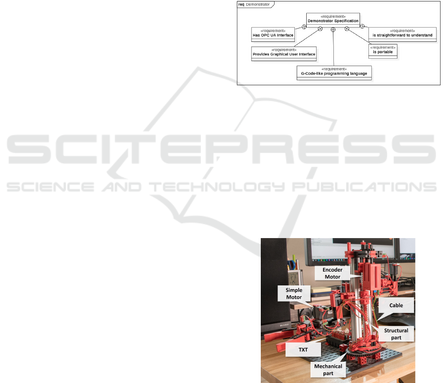
Figure 3: SysML requirements specification of the demon-
strator as the real counterpart for the FischerTwin.
3.2 Fischertechnik
TM
Robot
To make use of an existing physical asset, we decided
to use the FT modular construction system kit “swivel
arm robot” shown in Figure 4 with an overview of its
components. The use of an FT kit is beneficial, since
it yields an affordable, highly customisable, easily un-
derstandable and maintainable system, which covers
the requirements listed in the previous section.
Figure 4: Components of the FT swivel arm robot.
The swivel arm robot set consists of the physical
parts to build the robot, two types of motors, switches,
a control unit called TXT and cables to connect the
control unit with the motors and switches, see Fig-
ure 5. In the following, all components are introduced
The FischerTwin: An Experimentable Digital Twin Case Study
283
briefly.
Physical Parts. The physical parts of the swivel arm
robot include structural parts and mechanical parts
like gears and worm drives.
Motors. The motors included in the kit are electrical
motor which can be attached to other structural and
mechanical parts.
Switches. To determine if the robot has reached the
end of one of it axis, the FT kit uses limit switches.
They are placed to be pressed when one of the moving
parts reaches the end of an axis.
TXT. The TXT is the controller of the FT system. It
has electrical output ports to power motors and input
ports to read the states of switches and encoders. The
TXT is capable of running programs with read and
write access to these ports which allows to control the
physical robot.
While the controller provides a USB interface to
connect with other machines, it is not possible to na-
tively run the required OPC UA server on it. For this,
the robotic system requires the development of cus-
tom extensions.
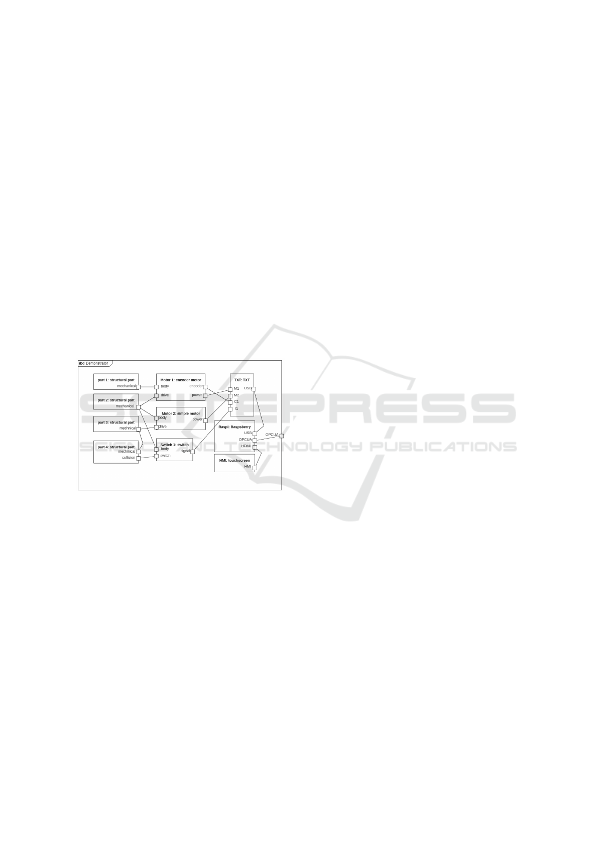
Figure 5: The simplified internal block diagram of the
demonstrator system.
4 EDT-BASED DEMONSTRATOR
DEVELOPMENT
Aside from the missing support of the OPC UA pro-
tocol to provide its current state, the swivel arm robot
lacked a text-based programming language and an
HMI akin to that of industrial machines. These are
the components requiring development from scratch
as opposed to the physical robot with its preexisting
functionality. While for the latter, an EDT has to be
created as its replica post-factum, the former can ben-
efit from an EDT throughout early development.
The design process can be divided into the design
of the SPA, the design of the DPS and the design of
the HMI, according to the the different parts of a CPS.
Since the TXT does not meet the user and OPC
UA interface requirements by itself, a Raspberry Pi
computer (RPi) connected to the TXT via its USB
interface serves as an intermediary. Its support of
Python-based programs enables the usage of libraries
including the required OPC UA server, a G-Code-like
command interpreter and tools to create the desired
HMI. Another Python library, called robopy, pro-
vides convenient access to the TXT’s USB interface.
4.1 Modelling Existing Components
In case of the demonstrator, the swivel arm robot (real
twin) was already developed but a readily available
EDT of it did not exist. This required us to create the
EDTs of its components and integrating them into our
own FischerTwin. As a first step of the process, we
made sure to have a 3D model of every FT part used
in the robot. While some 3D models of the parts are
openly available, we needed to manually model some
of them using a CAD tool. The EDTs of the FT parts
were then combined to construct the swivel arm robot
digitally in full analogy to the real twin. This 3D rep-
resentation constitutes the EDT’s geometric model.
As the essential functional property of a robot is
its ability to move, its EDT must also be able to move
for the development and operation of the demonstra-
tor system. To enable this, we integrated two more
EDT models complementing the geometric one, the
kinematic model and the dynamic model. The kine-
matic model purely represents the robot’s kinematic
structure and allows evaluating its possible motion.
For the dynamic model of the EDT, rigid body dy-
namics is used to move the robot under considera-
tion of forces. This allows the detailed evaluation of
the robot’s behaviour since the mass of moving parts
and the maximal motor torques are also taken into ac-
count. For the practical purposes of the FischerTwin,
this model consists of simplified geometric represen-
tations of the parts for efficient interactive simulation.
The motors and switches need to be created as
the next subordinate EDTs requiring more detail to
express the necessary behaviour and to complete the
physical asset. Both use rigid body dynamics: Mo-
tors apply external torques on the joints on which they
act, encoder motors can furthermore access the an-
gular deflection of that joint and switches make use
of collision detection to determine whether they are
pressed. To facilitate calibration, verification and val-
idation, we included correction factors into the com-
ponent models. All parts provide ports for the interac-
tion with the TXT controller. The EDTs of all struc-
tural and mechanical parts, the motors and switches
form the simulated physical asset.
SIMULTECH 2022 - 12th International Conference on Simulation and Modeling Methodologies, Technologies and Applications
284

The FischerTwin also contains EDTs of all com-
ponents of the DPS. The EDTs of the RPi and
the TXT controller are active instances of the VTB
database. The TXT has several ports which allow to
connect motors and switches to it and a USB port to
connect to the RPi. The RPi, in turn, provides a set of
functions, similar to the robopy library, which enable
a convenient way to send commands to the TXT over
USB. The connections between the TXT and the mo-
tors or switches are modelled in detail. Especially for
the use case of the system, it is necessary to simulate
errors in the data exchange between TXT and motors.
We therefore implemented a stochastic error model as
part of the simulated communication infrastructure.
The EDTs of the TXT and RPi are both part of the
simulated DPS. However, the part of the DPS that al-
lows to run robot programs and provides the OPC UA
interface is still missing on the digital as well as on
the real side.
4.2 Developing the High-level Control
Given the finished geometric and dynamic EDT rep-
resentation of all FT parts in conjunction with the
implementation of their connectivity, we design the
software components for the RPi. In accordance with
the requirements, their tasks are to provide the robot’s
state via OPC UA variables, to read in and to execute
G-Code-like robot programs and to provide a graphi-
cal HMI to control the programs’ execution. To fully
use the potential of the EDT methodology, we first
implement these components using the FischerTwin.
This allows testing all interfaces and potential robot
programs without the risk of damaging the real robot.
Moreover, it enables parallel development and test-
ing regardless of the availability of robot’s real twin
(or, in fact, its existence). The implementation makes
use of the set of functions provided by the RPi de-
scribed in Section 4.1. Since these functions are sim-
ilar to the aforementioned preexisting robopy library,
the software transfer to the real system is straightfor-
ward. Software development including bug fixing is
thus possible (and has been done here) using the EDT.
4.3 EDT Structure
As stated above, all EDTs of structural and mechani-
cal parts, of motors and of switches belong to the SPA,
the EDT of the TXT and of the RPi belong to the DPS
EDT component, the EDT of the HMI belongs to the
HMI EDT component and the cables together with
their error models belong to simulated communica-
tion infrastructure.
All components expose internal ports to the parent
EDT only if they require connections to EDTs in
other components, which enhances the overview and
reduces unnecessary structural clutter. The overall
EDT of the demonstrator system exposes one OPC
UA port. The resulting EDT is used, among other
things, for the development (as described in the pre-
vious section) and operation of the FeDiNAR system
the use case for the demonstrator system (see the next
section, Section 5).
5 EDT-BASED DEMONSTRATOR
OPERATION
The FischerTwin serves as the first demonstrator to
evaluate the technical feasibility of the central ideas
of the FeDiNAR project (Atanasyan et al., 2020). The
FeDiNAR system recognises its users’ actions by ob-
serving the state of the digital twin of an entire learn-
ing scenario. Real consequences are prevented, e.g.,
by putting the involved machine into a safe state, most
simply by initiating a (soft) emergency stop.
5.1 Application-related Life Cycle
Additions
Aside from additions to the VTB, the FeDiNAR prin-
ciples require additions to the interactive EDTs in the
learning scenarios—mainly that in case of some con-
sequences, their behaviour may need to be altered
from the nominal behaviour that is realised by the
originally implemented domain-specific algorithms.
This leads to changes at multiple points of the EDTs
life cycle:
• In the function phase, didactics add the goal of
displaying non-realistic but didactically helpful
behaviour.
• This adds requirements like non-programmed
movements or predefined animations.
• In the definition phase, the mechanisms for reali-
sation are laid out.
• During verification and implementation we cre-
ate and test the required software components ex-
tending the VTB by the necessary functionality.
• In the utilisation phase, the FischerTwin can fi-
nally express the new behaviour, providing valu-
able AR-based feedback to the user during learn-
ing task execution.
While we still use the FischerTwin and the real robot
at the time of writing, EDTs in general can serve as a
basis for analysis in the disposal phase depending on
the LoD of their included structural information.
The FischerTwin: An Experimentable Digital Twin Case Study
285
5.2 FischerTwin Learning Task
The main use of the FischerTwin in the utilisation
phase is to present consequences of errors in han-
dling the real robot in the context of a given learn-
ing task using augmented reality. Our mock task for
the demonstrator is the cleaning of a motor encoder
connector, which is supposedly dirty and does not re-
liably provide the correct height of the robot’s arm.
The mock learning task consists of four steps:
1. De-energise the motors by enabling the mainte-
nance mode using a switch.
2. Unplug the encoder connector.
3. Clean the connector with compressed air.
4. Re-attach the connector.
5. Disable the maintenance mode.
6. Run test program.
Here, we consider i) a mock critical error of not de-
energising the motors before cleaning the connector,
ii) the error of not properly cleaning it (not apply-
ing compressed air) and iii) of not re-attaching it to
the encoder. The test program moves the arm up to
a switch-based limit and down to a medium height,
which is defined by reaching a defined encoder value.
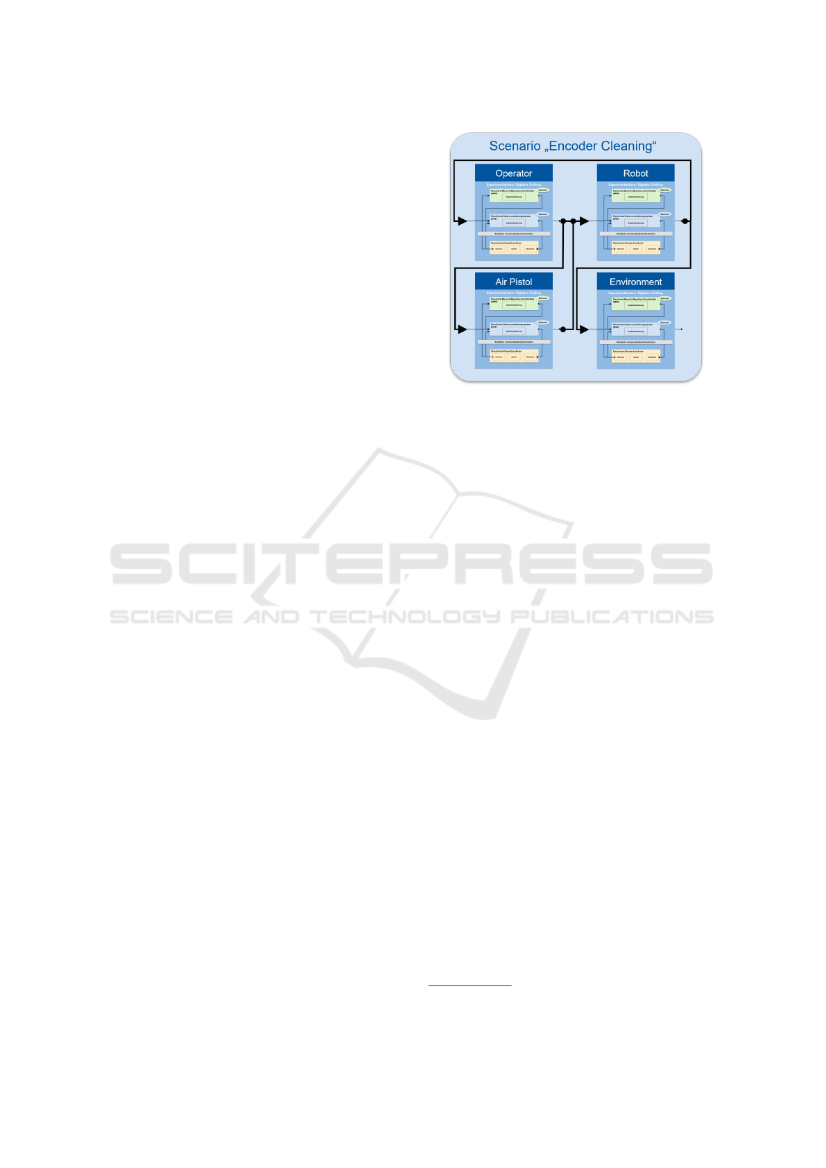
Figure 6 gives an overview of the EDT scenario
with the main involved components in the learning
Task. The scenario “Encoder Cleaning” consists of
the four main components “Operator”, “Robot”,“Air
Pistol” and “Environment”. The depicted high-level
overview shows their main logical connections: The
operator handles the robot by using the air pistol to
clean the robot motor’s dirty encoder connector. The
robot can interact with the environment and its EDT
can provide feedback to the operator in case of errors.
5.3 Role of the FischerTwin in the
FeDiNAR System
The system realising the learning task described in the
previous section makes strong use of the FischerTwin:
• To show the trainee the consequences of its action
in AR, the FeDiNAR system needs the geometri-
cal information provided by the FischerTwin.
• Consequences of actions by the trainee must be
simulated. For this we use two EDT-based meth-
ods described in detail in Section 5.4.
• The development of various FeDiNAR system
components was carried out in parallel although
we only had one physical demonstrator system.
By replacing the real system with the Fischer-
Twin, we could develop the FeDiNAR system
Figure 6: A FeDiNAR demonstrator EDT scenario.
without requiring the real robot. Since it and the
FischerTwin provide the exact same interfaces,
seamless transitions from the EDT to the real sys-
tem and back were possible.
In context of the FeDiNAR system, the FischerTwin
is only one EDT among many others. Their encap-
sulated structure helps to develop all system compo-
nents independently from one another and, equally, to
structure the overall system.
5.4 Error Consequences
In FeDiNAR, we distinguish between simulation-
based white-box consequences and pre-programmed,
didactically helpful black-box consequences. FeD-
iNAR scenarios feature a Petri-net-based task logic
which can trigger black-box consequences given ac-
cording system states. This is the case for error i):
the black-box consequence wiggle arm back and forth
“Don’t touch me!” is triggered when during the error
state, the distance of the trainee’s hand to the encoder
connector falls below a defined threshold. Errors ii)
and iii) have white-box consequences: When the en-
coder is disconnected and the trainee starts a testing
program, the EDT does not receive the motor posi-
tion. The motor does therefore not stop at the desired
height but moves down indefinitely—the real robot’s
arm would crash into the base and potentially cause
motor damage due to overheating. A dirty connector
either stops later than desired or also causes a crash.
A video of the task execution in the testing phase
using the HoloLens 1 is available online.
2
2
https://youtu.be/1Hw79nHFEYc
SIMULTECH 2022 - 12th International Conference on Simulation and Modeling Methodologies, Technologies and Applications
286

6 CONCLUSION AND FUTURE
WORK
With this contribution, we presented exemplarily how
to use the experimentable digital twin (EDT) ap-
proach in the life cycle of a complex cyber-physical
system (CPS). Using the ECSS project phase defini-
tion, we combined the approach with an MBSE-like
strategy during the first phases and used the EDT up
until the utilisation phase. Our presented system is
a demonstrator using a fischertechnik
TM
swivel arm
robot. We named its EDT, which we developed in
high detail and use here for illustration, the Fischer-
Twin. During its and its real twins life cycle we had a
number of findings.
The structural and behavioural identity of the
twins offers enormous benefits as, given EDTs of the
environments, in which the CPS is used, extensive
testing can be performed virtually. This is valid for
the hardware and software of the CPS. This way, ex-
pensive physical prototypes for simulatable tests can
be entirely omitted and parallel development of many
components is possible with limited to no access to
the real system. In our case, the development of a
robotic command interpreter, an OPC UA communi-
cation interface and a graphical human-machine inter-
face was possible purely using the EDT with minimal
effort for transfer to the real system.
The testing and development relies on a virtual
testbed (VTB, as the runtime environment for EDTs)
allowing the simulation of the required environments
in all relevant disciplines (kinematics, rigid body dy-
namics, sensors, wiring, etc.). For use cases actively
using EDTs in the utilisation phase, parallel devel-
opment of EDT and VTB may be necessary. In our
case, this was, among others, the addition of pre-
programmed “black-box behaviour” for didactic pur-
poses and the ability of the VTB to perform non-linear
simulation progressions (“jumps back in time”) and
switching between a mode of mirroring the state of a
real twin to its EDT and using the latter to perform
simulation for a “look into the future”.
At the time of writing, we continue to use the Fis-
cherTwin for scenarios of varying complexity; among
others, to generate training data for AI-based state
recognition. While it is usable in its current form,
we intend to continue the extension and refinement
of some of the FischerTwin’s partial models, e.g., a
more detailed rigid body dynamics representation and
a higher fidelity signal transmission model between
its components.
ACKNOWLEDGEMENT
The writing of this work was enabled in part from
within the context of the FeDiNAR project. It is
funded by the Federal Ministry of Education and Re-
search (BMBF) as part of the “Digital Media in Vo-
cational Education and Training” programme and is
supported by the German Aerospace Center (DLR)
under the funding code 01PV18005A.
REFERENCES
Atanasyan, A., Kobelt, D., Goppold, M., Cichon, T., and
Schluse, M. (2020). The FeDiNAR project: Using
augmented reality to turn mistakes into learning op-
portunities. In Augmented Reality in Education, pages
71–86. Springer.
ECSS Secretariat (2009). ECSS-M-ST-10C space project
management–project planning and implementation.
ESA-ESTEC Requirements & Standards Division, No-
ordwijk, Netherlands.
Grieves, M. (2015). Digital twin: Manufacturing excellence
through virtual factory replication.
Kadry, S. and El Hami, A. (2019). E-Systems for the 21st
Century: Concept, Developments, and Applications-
Two Volume Set. CRC Press.
OMG SysML (2022). Object management group systems
modeling language. http://www.omgsysml.org/.
OMG UML (2022). Object management group unified
modeling language. http://www.omg.org/spec/UML/.
Osterloh, T., Dahmen, U., and Roßmann, J. (2018). Full
lifecycle support for modular satellite systems pro-
vided by comprehensive virtual testbeds. In iSAIRAS.
Roßmann, J. and Schluse, M. (2020). Experimentierbare
digitale zwillinge im lebenszyklus technischer sys-
teme. In Handbuch Industrie 4.0: Recht, Technik,
Gesellschaft, pages 837–859. Springer.
Schluse, M., Atorf, L., and Rossmann, J. (2017). Ex-
perimentable digital twins for model-based systems
engineering and simulation-based development. In
2017 Annual IEEE International Systems Conference
(SysCon), pages 1–8.
Schluse, M., Priggemeyer, M., Atorf, L., and Rossmann, J.
(2018). Experimentable digital twins—streamlining
simulation-based systems engineering for industry
4.0. IEEE Transactions on Industrial Informatics,
14(4):1722–1731.
Schluse, M. and Rossmann, J. (2016). From simulation to
experimentable digital twins - simulation based devel-
opment and operation of complex technical systems.
In Second IEEE International Symposium on Systems
Engineering (ISSE 2016), October 3-5, Edinburgh,
Scotland, pp. 273-278. IEEE.
Tao, F., Zhang, H., Liu, A., and Nee, A. Y. C. (2019). Dig-
ital twin in industry: State-of-the-art. IEEE Transac-
tions on Industrial Informatics, 15(4):2405–2415.
The FischerTwin: An Experimentable Digital Twin Case Study
287
