Telerobotic Radiation Protection Tasks in the Super Proton Synchrotron
using Mobile Robots
David Forkel
1,2 a
, Enric Cervera
2 b
, Ra
´
ul Mar
´
ın
2 c
, Eloise Matheson
1 d
and Mario Di Castro
1 e
1
BE-CEM-MRO - European Organization for Nuclear Research, Espl. des Particules 1, 1211 Meyrin, Switzerland
2
Jaume I University, Avinguda de Vicent Sos Baynat, s/n, 12006 Castell
´
o de la Plana, Castell
´
o, Spain
Keywords:
Hazardous Environment, Automatic Inspection, Mobile Robot, Telerobotics.
Abstract:
In this paper a complete robotic solution is presented, which allows the teleoperation of the radiation survey
in the Super Proton Synchrotron (SPS) accelerator at CERN. Firstly, an introduction to radiation protection is
given. Subsequently, the execution of the radiation survey in person is described and the potential of robotic
solutions for such missions is outlined. After providing a brief state of the art on the subject, the development
of the robot base, as well as its component selection and design is shown. Hereafter, the software implemen-
tation is explained. The test procedure of this project includes the most important requirements for a correct
execution of the survey, as well as the operational steps and data treatment in detail. The results underline
the correct execution of the mission, and show the advantages of the teleoperated robotic solution, such as the
improved and unified measurement conditions. Thus, this robotic system will allow to significantly reduce the
radiation dose of the radiation protection staff. For further development, the automation of this task is planned,
which presupposes the gradual autonomization of the robotic system from assisting the user to the self-reliant
execution of the survey.
1 INTRODUCTION
1.1 On the Importance of Radiation
Protection at CERN
CERN operates the world’s largest accelerator com-
plex to provide high energy particle beams to a world-
wide community of physicists who are studying the
basic constituents of matter. To this end, researchers
investigate the products of collisions between high
energy particles with the help of sophisticated par-
ticle detectors and analysis software. CERN’s ac-
celerator complex straddles the French-Swiss border
near Geneva. The so-called injectors (LINAC4, Pro-
ton Synchrotron (PS) and Super Proton Synchrotron
(SPS)) of the Large Hadron Collider (LHC) and the
LHC itself successively accelerate the particles to in-
creasingly higher energy. Finally, the two LHC proton
beams are brought into collision at the so-called col-
a
https://orcid.org/0000-0001-7947-8282
b
https://orcid.org/0000-0002-5386-8968
c
https://orcid.org/0000-0002-2340-4126
d
https://orcid.org/0000-0002-1294-2076
e
https://orcid.org/0000-0002-2513-967X
lision points of the four LHC experiments (ATLAS,
CMS, LHC-b and ALICE) with a center of mass en-
ergy of 14 TeV (CERN, 2022).
The operation of accelerators is inevitably related
to the loss of beam particles, either intentionally e.g.
through collimation, dumping or collisions or acci-
dentally by degraded beam transmission. The “lost”
particles interact with other particles (collisions) or
matter. Radioactive isotopes are created by various
nuclear processes and in function of type and energy
of the ”lost” particle and the chemical properties of
the matter. As a consequence, the accelerator and de-
tector components, tunnel structure, liquids like wa-
ter and gases like air become radioactive. The gamma
and beta radiation fields caused by the radioactive de-
cay of the induced radioactive isotopes (“residual ra-
diation”) represent the major source for radiation ex-
posure of workers to ionising during repair and main-
tenance of the accelerators and detectors. The pri-
mary objective of Radiation Protection (RP) at CERN
centers on minimizing the exposure of individuals to
ionizing radiation. Furthermore, the reduction of the
radiological impact on the surrounding environment
is assigned an overriding role (Forkel-Wirth et al.,
2013). The main principles of radiation protection
Forkel, D., Cervera, E., Marín, R., Matheson, E. and Di Castro, M.
Telerobotic Radiation Protection Tasks in the Super Proton Synchrotron using Mobile Robots.
DOI: 10.5220/0011276600003271
In Proceedings of the 19th International Conference on Informatics in Control, Automation and Robotics (ICINCO 2022), pages 451-458
ISBN: 978-989-758-585-2; ISSN: 2184-2809
Copyright
c
2022 by SCITEPRESS – Science and Technology Publications, Lda. All rights reserved
451
legislation have been defined in Recommendation 60
published by the International Commission on Radi-
ological Protection (ICRP, 1991). They are described
as follows:
• Justification of the practice: Any practice involv-
ing the exposure of persons to ionizing radiation
requires justification.
• Optimization of protection: Procedures that result
in radiation exposure of individuals must be sub-
ject to a continuous optimization process to re-
duce the radiation doses received by the affected
persons. In addition, the ALARA principle ap-
plies, according to which personal and collective
doses must always be kept as low as reasonably
achievable.
• Dose limits: The legal limits regarding personal
radiation doses must be respected.
These recommendations have been fully integrated
into CERN’s radiation safety code (CERN, 2006).
1.2 The Radiation Protection Survey in
the Super Proton Synchrotron (SPS)
Radiation surveys of CERN accelerators are a long-
standing practice and part of CERN’s approach to
ALARA. Their purpose is twofold:
1. Measuring the radiation dose rate along the accel-
erator for a radiological risk assessment and input
for the organisation and dose planning of repair
and maintenance work.
2. Supporting beam-operation in its search for lo-
cations of beam-losses and optimization of trans-
mission.
Radiation surveys in the SPS accelerator have
been performed by CERN personnel (Kershaw et al.,
2013). A radiation protection technician in an electri-
cal vehicle drives along the 7 km circumference of the
accelerator. The dose rate is continuously measured
with a radiation detector from about 70 cm distance
from the machine components and at the height of the
beam axis. Such a survey results in approximately
20,000 data points. This general survey is refined by
a more detailed survey of the six Long Straight Sec-
tions (LSS) of the tunnel by radiation protection tech-
nicians walking along the accelerator. They measure
the dose rates at 40 cm distance and on contact of the
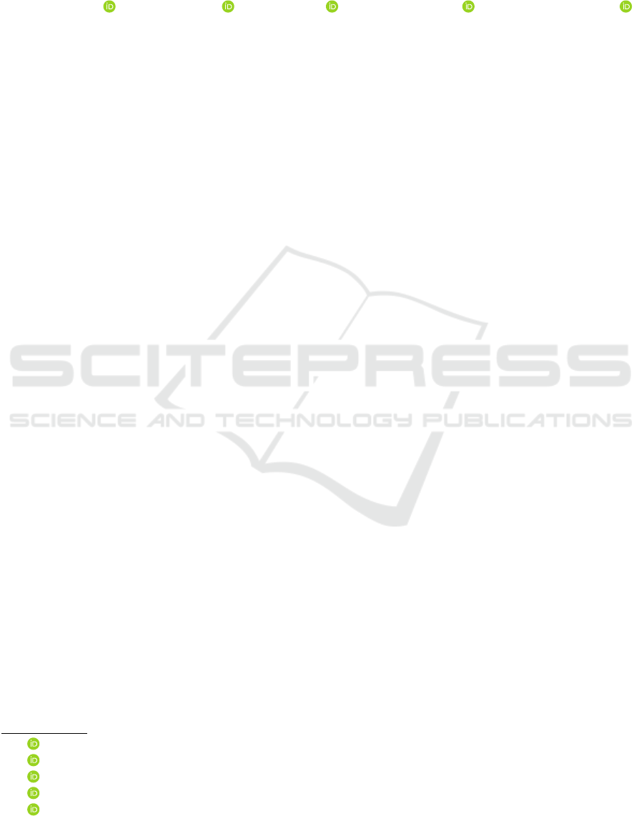
accelerator components. After visualizing the data,
the results of the general survey are used as an indi-
cator of locations of increased radiation levels and for
information of the operational team on the develop-
ment of beam loss points whereas the data of the de-
tailed survey are used for job and dose planning. Typ-
ical results can be seen in Figure 1 (D. Forkel-Wirth,
M. Silari (Editors), 2010).
Figure 1: Radiation survey results 2008/09 realised in sector
2 of the SPS.
1.3 Opportunities and Challenges of
Mobile Robotic Solutions for
Inspection at CERN
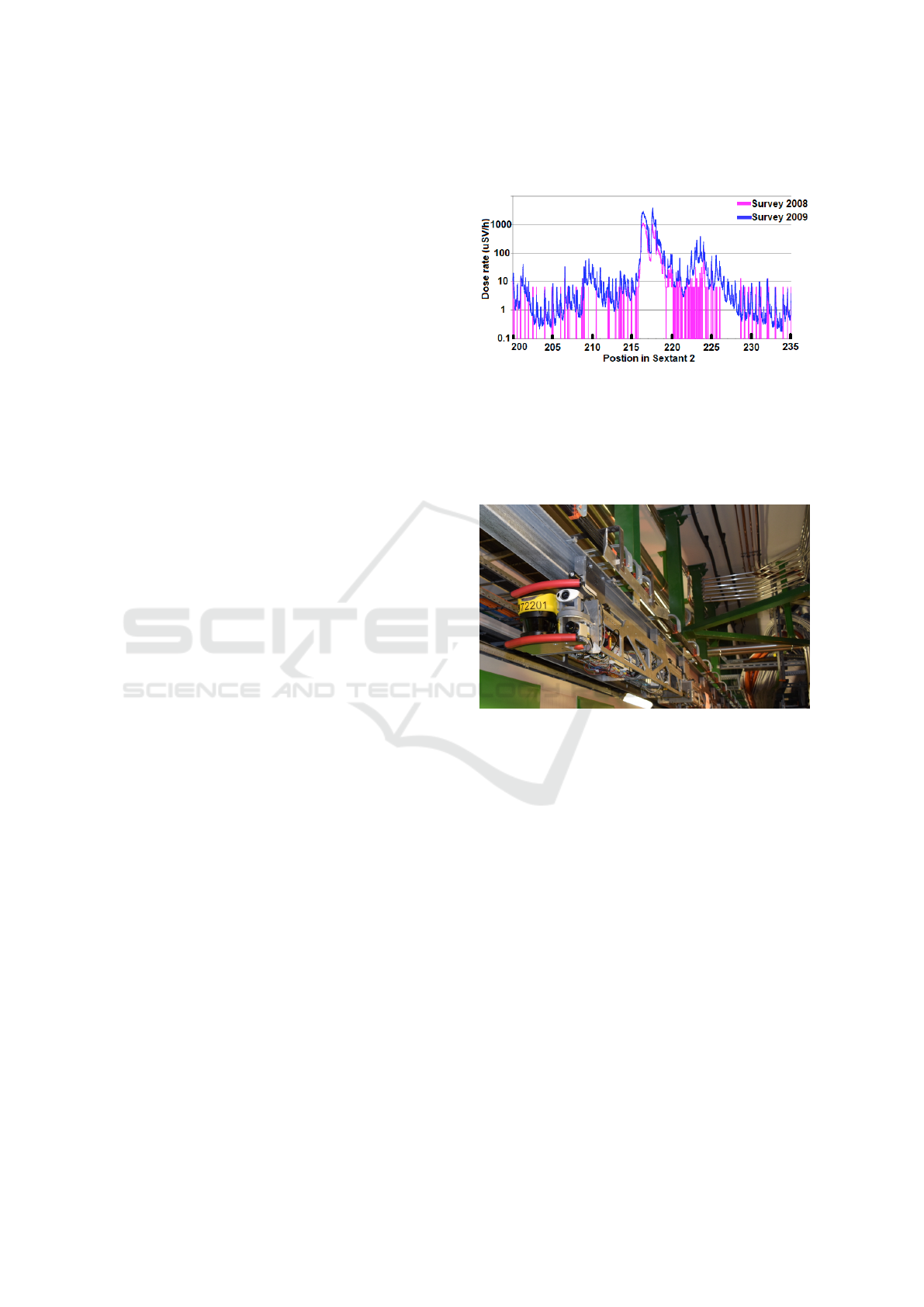
Figure 2: Train Inspection Monorail (TIM).
Regarding the potential of robotic solutions for in-
spection it must be stated that CERN has been ex-
ploiting robots for a long time – in the beginning
mainly for handling highly radioactive components
like the ISOLDE targets (Catherall et al., 2017). A
new type of robot had been successfully developed
for the LHC, the multi-functional Train-Inspection-
Monorail (TIM) shown in Figure 2 (Alessandro Masi,
2017). As the name indicates, it combines an elec-
trical train with a monorail that already existed in the
Large-Electron-Positron (LEP) Collider, the accelera-
tor that was preceding the LHC. TIM is regularly used
for visual inspections in the LHC accelerator tunnel,
functional tests of the 3,600 beam-loss-monitors and
radiation surveys. In the latter case, TIM performs
both the general and the detailed radiation survey
(Castro et al., 2018). These functions allow a consid-
erable reduction of accelerator down-time as the tasks
can start immediately after beam stop, and limits the
needs of personnel carrying out this task.
TIM shows the advantages of robotic solutions,
ICINCO 2022 - 19th International Conference on Informatics in Control, Automation and Robotics
452

being a very versatile and promising tool for vari-
ous types of inspections in radioactive environments.
Robotic solutions contribute to the overall objective
of optimizing inspection and maintenance tasks in the
accelerator complex, both in view of radiation protec-
tion of workers and the overall efficiency increase of
beam operation.
2 STATE OF THE ART ON
TELEOPERATED ROBOTIC
INSPECTION SYSTEMS IN
HAZARDOUS ENVIRONMENTS
Complex scenarios such as accelerators, underwater
facilities and nuclear plants require a high degree of
knowledge in order to be able to inspect and also in-
teract with the environment safely (Veiga Almagro
et al., 2020). Sometimes the necessary knowledge to
inspect a scientific facility such as the ones at CERN
is not only present in a single person, so the use of a
telerobotic system is mandatory (Lunghi et al., 2019).
In fact, the situation becomes even more critical
when the communication channel is constrained, a
challenge that can be partly mitigated by giving more
intelligence to the robot, so that the operator interacts
in a more supervised way, while reducing the need
of communication bandwidth. This is the case of un-
derwater robots which, once submerged, can maintain
the communication link via Visual Light Communica-
tion and Radio Frequency modems at short distances,
and sonar at long distances, being necessary to ad-
just the level of autonomy accordingly (Rubino et al.,
2017).
In these kind of hazardous environments it is nec-
essary and convenient to perform a pre-inspection of
the environment, before deciding the next steps in or-
der to perform, for example, maintenance operations.
The most recent research experiments performed in
this field involve the use of multiple robots, being able
to cooperate in order to recover, and transport big ob-
jects (Pi et al., 2021).
A significant state of the art on teleoperated robots
for exploration and inspection is also represented by
the latest developments of the lunar rover as part
of the YUTU-2 mission. In February 2022, several
small intact spheres of translucent glass were discov-
ered and inspected. This glass can contain informa-
tion about the moon’s history, including the composi-
tion of the lunar mantle and impacts (Michelle Starr,
2022).
Another indispensable application of telerobotic
systems involves radioactive environments. Robots
are increasingly taking over tasks at nuclear plants
to simplify inspection procedures or reduce the ra-
diation exposure of the personnel. One example is
the LAROB underwater robot, which can remotely
inspect reactor vessels in nuclear power plants under
laser guidance. LAROB contributes to carrying out
the mandatory inspections more efficiently, while re-
ducing the operator’s workload. As a result, the sys-
tem has the potential to drastically reduce the critical
path of reactor vessel inspection (Kim et al., 2014).
3 A MOBILE ROBOTIC
SOLUTION FOR RADIATION
PROTECTION OPERATIONS
3.1 Hardware
3.1.1 Omnidirectional Robot Base
For the SPS radiation survey, a new robot has been
designed at CERN. An omnidirectional base was cho-
sen, using four mecanum wheels located in paral-
lel (Prados Sesmero et al., 2021). The omnidirec-
tional behavior of the platform is created by the pas-
sive rollers attached to each wheel. The movement
of these in combination with the rotary motion of the
four wheels results in a force transfer in another direc-
tion, in such a way that sideways and diagonal move-
ments, as well as rotations around the center of the
base, are made possible. The rubber rollers are pro-
tected by the wheel frame. Depending on the ground
conditions, a different movement behavior can be ob-
served. Especially on smooth or slippery surfaces,
a slippage of the wheels and the rollers can occur,
which results in a misalignment in any direction (Park
et al., 2010).
The frame structure and arrangement of the
mecanum wheels in the longitudinal direction at the
bottom corners of the frame provides several advan-
tages. First of all, the design is simplified, offers suffi-
cient and equal space for motor mounting and allows
the connection of these motor sets centrally within the
frame. Moreover, this structure is compact and allows
all required sensors and other hardware to be housed
within the frame, so that only the wheels extend from
the frame. This offers significant advantages in ma-
neuverability when traversing narrow passages or lim-
ited spaces. Another benefit is the redundancy of the
system. Thus, even in the event of a motor failure, it
is still possible to complete the robot’s tasks through
controlling the three remaining wheels. In addition,
adjustment and correction algorithms in the kinematic
Telerobotic Radiation Protection Tasks in the Super Proton Synchrotron using Mobile Robots
453
model can compensate for such an error.
However, this locomotion arrangement presents
some disadvantages that need to be considered: The
aforementioned slippage of the mecanum wheels re-
sults in a positioning error that can falsify the odom-
etry. It is therefore crucial that the localization of the
robot is not based on the motor encoder values alone,
but rather supported by additional sensors such as
cameras (visual odometry), LiDAR’s (LiDAR odom-
etry) or IMU’s. Another disadvantage concerns the
energy efficiency of the wheels, that is significantly
lower than of conventional ones, which translates into
increased battery consumption. This can be compen-
sated for by sufficient battery planning, as well as a
reduction in the maximum speed, which must be ap-
plied in any case due to the safety regulations within
the tunnel system of the accelerator complex.
3.1.2 Sensor and Component Selection
The following devices were selected for equipping the
omndirectional base (Prados Sesmero et al., 2021):
• 3 cameras (Axis F44 main unit / F1035-E sensor
units) providing a high definition camera stream
for teleoperation
• an inertial measurement unit (VMU931), con-
tributing to the localization accuracy of the robot
base
• a radiation sensor (Atomtex BDKG24) to measure
the radiation dose rate
• a 4G LTE Wi-Fi router (Teltonika RUT240) al-
lowing external access over a client in a different
network, as well as local communication for test-
ing
• a robot arm that moves the radiation sensor into
the optimal measurement position and also per-
mits a detailed visual inspection with the attached
gripper camera. The Kinova® Jaco 2 is used.
Moreover, the robot features a small form factor
PC for the execution of all processes. The cameras,
as well as the Kinova® robot arm, are connected to
the network interface of the PC via an Ethernet hub.
3.1.3 Mechanical Design
The main structure of the mechanical design is char-
acterized by the use of aluminum profiles. These give
the system robustness and rigidity. Furthermore they
guarantee the protection of the internal components.
The main characteristics of the design are the fol-
lowing:
• Four lead acid batteries, placed on the sides. The
capacity of these are 15 Ah, which guarantees
about 4 hours of operation, depending on the ve-
locity of the base as well as the robot arm usage
• A magnetic connector that facilitates the correct
launch of the charging process
• Four possible localization for cameras or Li-
DAR’s behind the wheels, placed where the field
of view is sufficiently large
• A support for the radiation sensor attached to the
end effector of the robotic arm
The main dimensions of 526 × 360 × 190 mm,
were chosen to allow the passage of the robot through
the cut-out gaps of the security doors that are separat-
ing the various accelerator sectors. The weight of the
robot amounts to approximately 45 kg, including the
robot arm and all necessary components. The reach
of the mounted robot arm including the radiation sen-
sor is approximately 1100 mm (Prados Sesmero et al.,
2021). The robotic arm has been placed so that it can
fold down below the height of the base to allow ma-
neuverability in low-profile environments, such as the
secure gate cut-out. The gripper camera serves as a
visual guidance for the operator. Besides the radia-
tion surveys, the combination of robot arm and cam-
era allows a wide variety of additional teleoperation
tasks. Visual inspection of accelerator components
and infrastructure, leak repair, drilling, component re-
placement welding, as well as visual, variable check-
ing (measuring oxygen concentration or temperature)
and many more, can be performed by replacing the
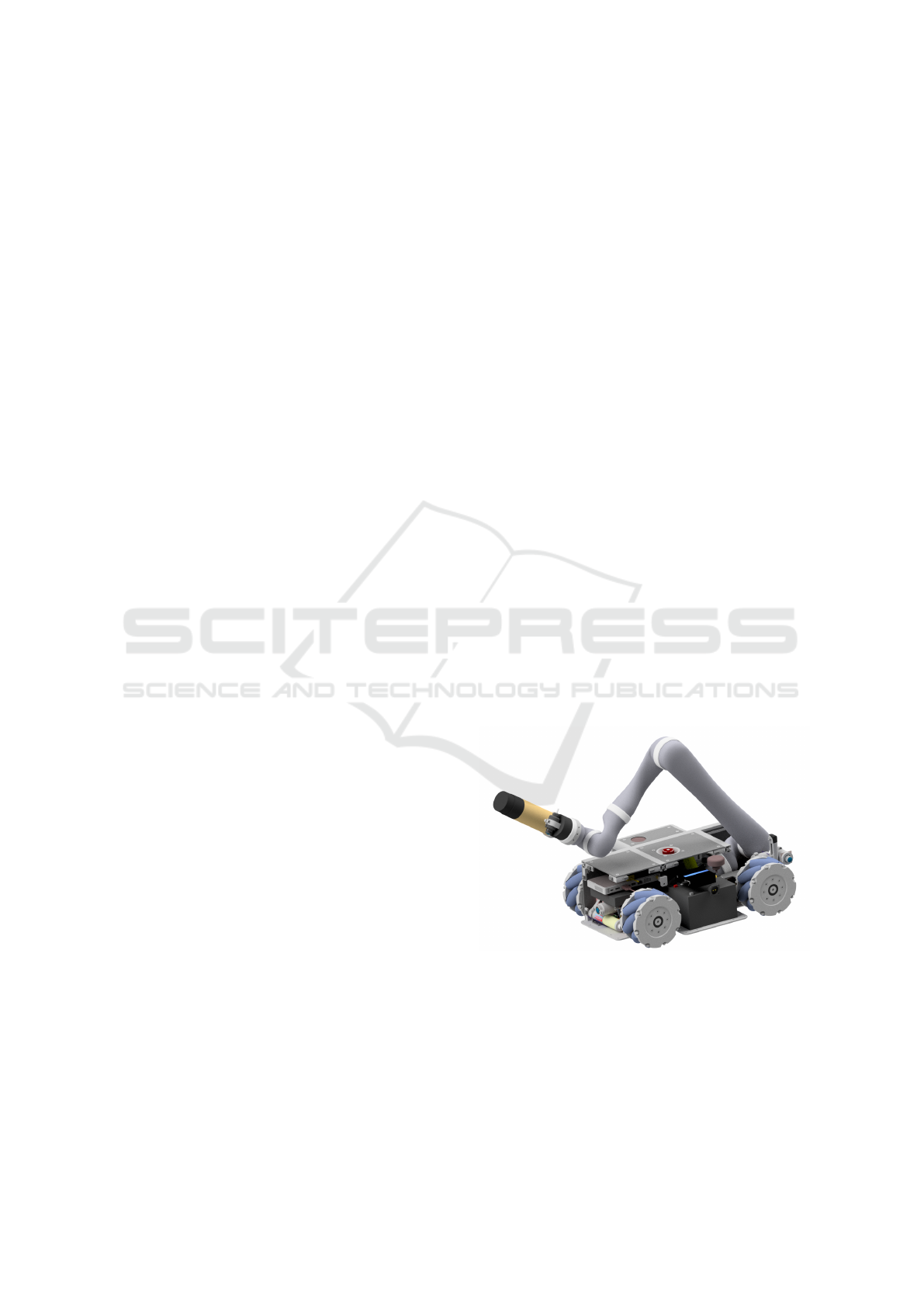
end effector tool. Figure 3 shows the fully equipped
robot.
Figure 3: Cross-section of the omnidirectional robot base
with Kinova® Jaco 2 robot arm.
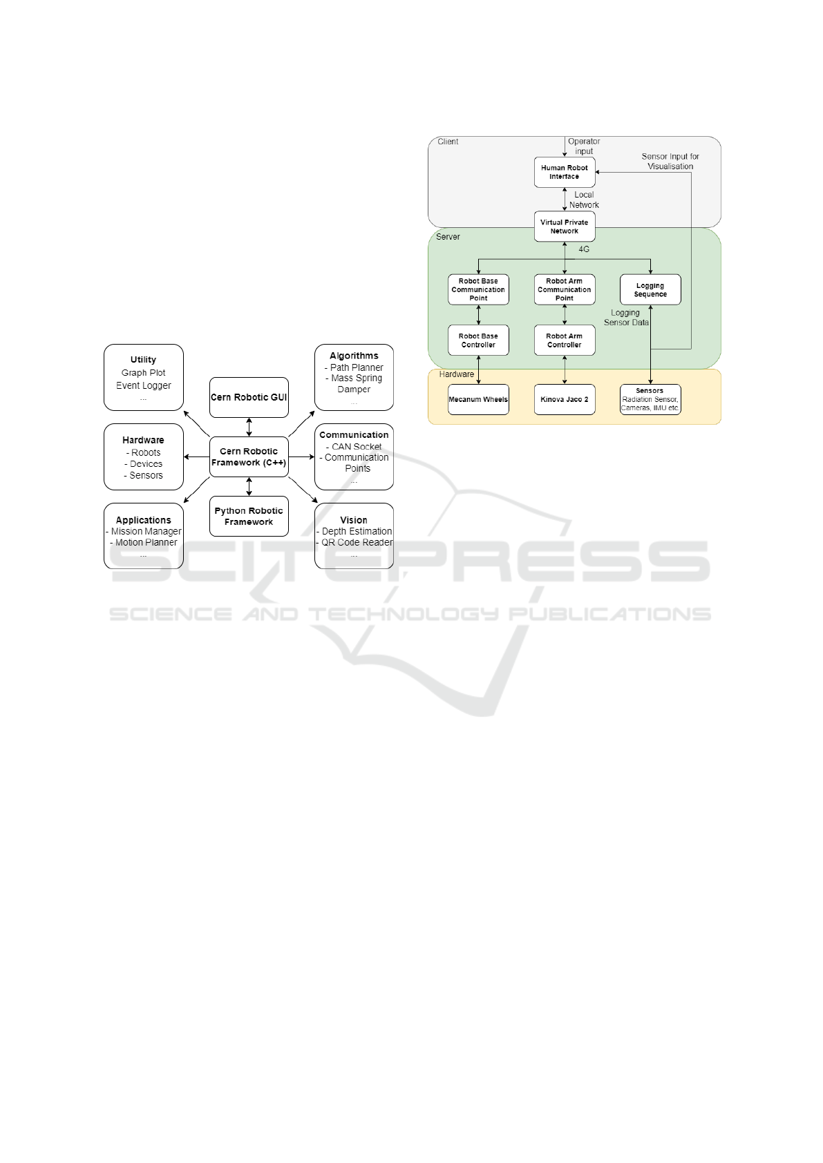
3.2 Software Implementation
3.2.1 The CERN Robotic Framework (CRF)
The Cern Robotic Framework represents an innova-
tive modular architecture for robotic inspection and
ICINCO 2022 - 19th International Conference on Informatics in Control, Automation and Robotics
454
telemanipulation in harsh and semi-structured envi-
ronments (Di Castro et al., 2018). It covers all aspects
of robotic interventions at CERN, from the specifica-
tion and operator training, the choice of the robot and
its material best suited for an environment with radio-
logical hazards, to the realization of the intervention,
including procedures and recovery scenarios. Thus,
it can be described as a multidisciplinary toolbox that
represents a complete in house software solution and
is indispensable for the operation of ongoing inter-
ventions as well as the development of new robotic
projects at CERN. Figure 4 shows the scope of this
framework.
Figure 4: Modules of the Cern Robotic Framework (CRF).
3.2.2 Overall Architecture
The overall architecture of the robotic control system
is shown in Figure 5.
At the top of the structure stands the Human Robot
Interface, which allows the operator to take control
of all necessary components of the robot, while be-
ing informed about the current status. In this case,
the operator can control the robot base and robot arm
independently via keyboard or controller input. For
visual orientation, the four video streams of the cam-
eras attached to the robot are displayed. In addition,
the current radiation dose measured by the radiation
sensor attached to the robot arm and the current ve-
locity of the base are indicated. Using the local net-
work connection, the client connects to a virtual pri-
vate network to which the server in the robot is also
connected. This allows a remote launch of the Robot
Arm - and Robot Base Communication Point on the
server PC. The communication points establish the
connection between the Graphical User Interface and
the robot. For this purpose, the Transmission Control
Protocol (TCP) is used. The communication points
start the control loops for the robot base and the robot
arm and thus the mecanum wheels of the robot base
Figure 5: Overall architecture of the teleoperated robot for
the robotic radiation survey.
and the joints of the Kinova® Jaco 2 can be teleop-
erated by the HRI on the client side. Furthermore,
the logging sequence can be launched. It accesses
the built-in odometry of the robot base, as well as the
radiation sensor data. The collected data are subse-
quently stored locally on the robot’s PC.
4 EXPERIMENTAL EVALUATION
4.1 Test Procedure
4.1.1 Preliminary Requirements
In order to carry out a successful radiation survey,
several requirements need to be considered during the
operation. Worth pointing out are the safety mea-
sures, such as the secured operation without human
interaction, as well as the importance of protecting
the equipment and machines in the tunnel from any
damage that might be caused through robotic opera-
tion.
Considering this early test phase, it was therefore
decided to start the operation after the regular work-
ing hours, and in consultation with the CERN Control
Centre (CCC), which gave clearance to use the robot
for a robotic intervention inside the tunnel of the SPS.
Furthermore, two operators carried out the mission in
order to guarantee a review of the execution steps and
to gain a better overview of the overall situation. The
maximum velocity of the robot during the survey was
limited to 1.5 m/s. This measure ensured a safer oper-
ation by limiting the probability of potential crashes
Telerobotic Radiation Protection Tasks in the Super Proton Synchrotron using Mobile Robots
455
with structural elements or equipment in the tunnel of
the SPS.
Since the aim of the robotic radiation survey, as in
the manual survey, described in section 1.2 , is to mea-
sure the radiation dose rate along the SPS machine, it
is therefore also necessary to comply with the require-
ments given by this inspection process. This includes
respecting a maximum distance of 70 cm to the beam
axis when taking the survey measurements. Further-
more, the operation time shall not exceed 2 hours,
in order not to significantly disrupt maintenance ac-
tivities in the SPS. An additional difference between
the teleoperated execution of the survey compared to
the existing procedure concerns the 19 security doors,
which are normally opened manually by the person-
nel, but have to be passed with the robot through a
cut-out rectangle measuring 30 cm x 40 cm.
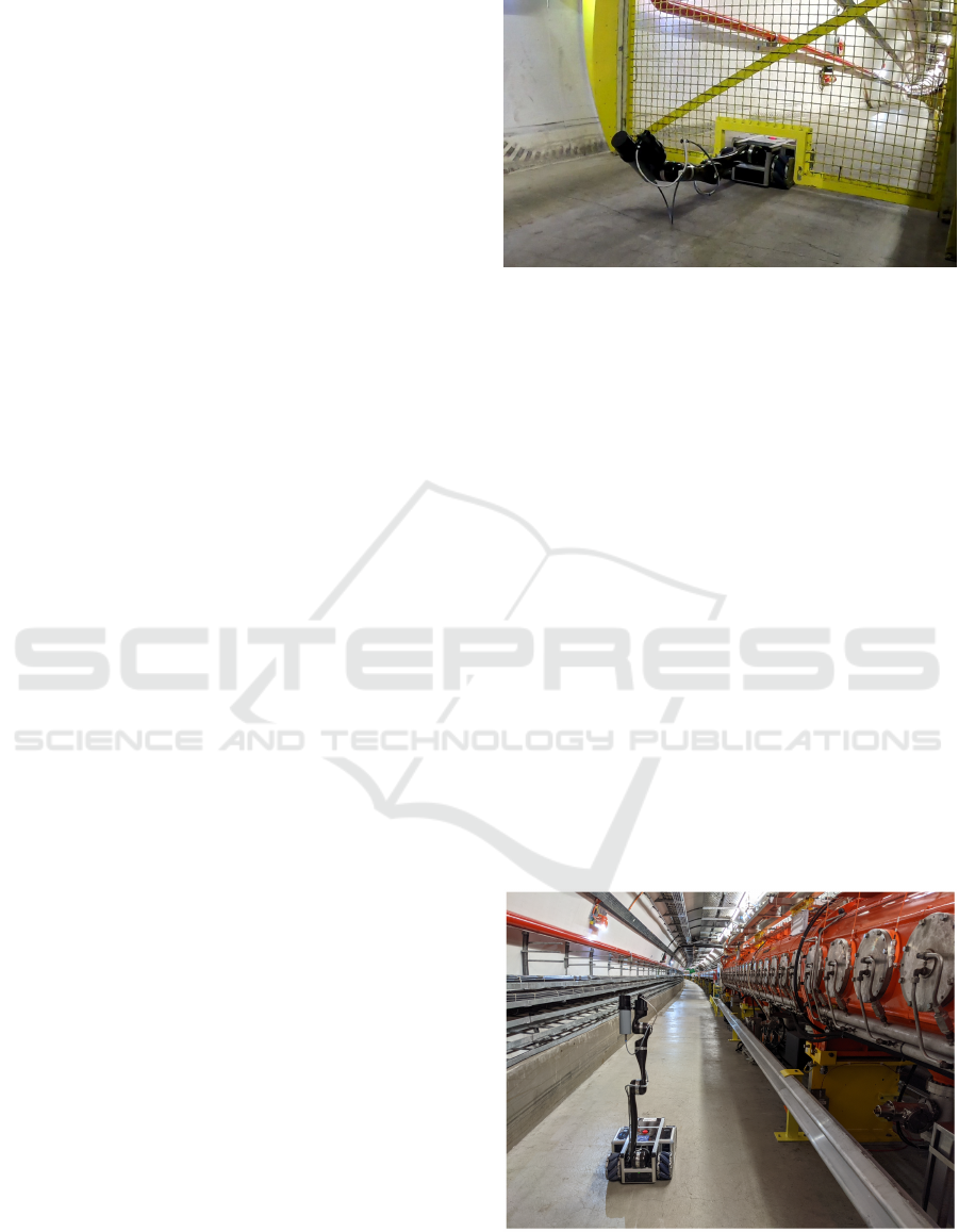
4.1.2 Operation Steps
The mission starts by activating the robotic sys-
tem. The charging is interrupted and the commu-
nication points of the robot base and the robot arm
are launched. By using the CERN Robotic GUI, the
robot is then moved out of the charging station, and
the robot arm is brought into an upright position so
that the radiation sensor is aligned with the beam axis.
After this, the system is ready for operation. To start
the survey, the closest security gate is approached to
provide a precise localization point at the beginning
of the data recording. The security gates are passed
by folding the robot arm back in such a way that the
arm is below the height of the robot base like shown
in Figure 6. The camera on the end effector is used
for guidance through the cut-out in the gate. Directly
after passing the gate, the robot arm is brought back
into the operation pose illustrated in Figure 7. The
logging sequence for measuring the radiation dose is
subsequently launched and the data is saved locally on
the storage medium of the PC. The data set includes
the measured radiation dose, as well as the odometry
data of the motor encoders integrated in the mecanum
wheels. In the following data analysis, this allows the
mapping of the measured radiation value to its posi-
tion in the SPS tunnel.
The measurements are always recorded from one
safety gate to the next, resulting in a total of 19 data
sets. The path between the start and end point is com-
pleted in one continuous run at a constant speed of 1.5
m/s. The maximum distance to the beam axis of 70
cm is maintained, using line markings as a reference
during the operation through the gripper camera. Spe-
cial attention has to be paid to the connection status
between the robot and the 4G repeaters in the tunnel
system of the SPS. By monitoring the ping develop-
Figure 6: SPS robot passing one of the 19 secure doors.
ment between client and server pc, conclusions can
be drawn about connection problems before the com-
plete loss of control occurs. If in exceptional cases
there may be a temporary loss of control, the veloc-
ity of the robot is automatically set to 0. However,
the robot base has no brakes, therefore the wheels
will coast before coming to a complete stop. In addi-
tion, the ground conditions must be taken into account
during teleoperation. As the floor is often inclined,
counter steering is required in order to maintain a con-
stant distance to the magnets. In addition, especially
in the vicinity of the 6 access points, the operator must
be aware of any cables, maintenance tools or other
objects in the way and navigate around them. Once
the 7 km circumference of the SPS tunnel has been
covered and all 19 secure gates have been passed, the
robot arm can now be brought back into the parking
pose and the base will be driven into the charging sta-
tion. Subsequently, the locally saved measurements
are transferred to the client PC and the charging pro-
cess is launched. In the most recent surveys, a total
operation time of 1h 40’ - 1h 55’ was measured, and
therefore, the limit of 2 h was respected.
Figure 7: SPS Robot taking radiation measurements.
ICINCO 2022 - 19th International Conference on Informatics in Control, Automation and Robotics
456
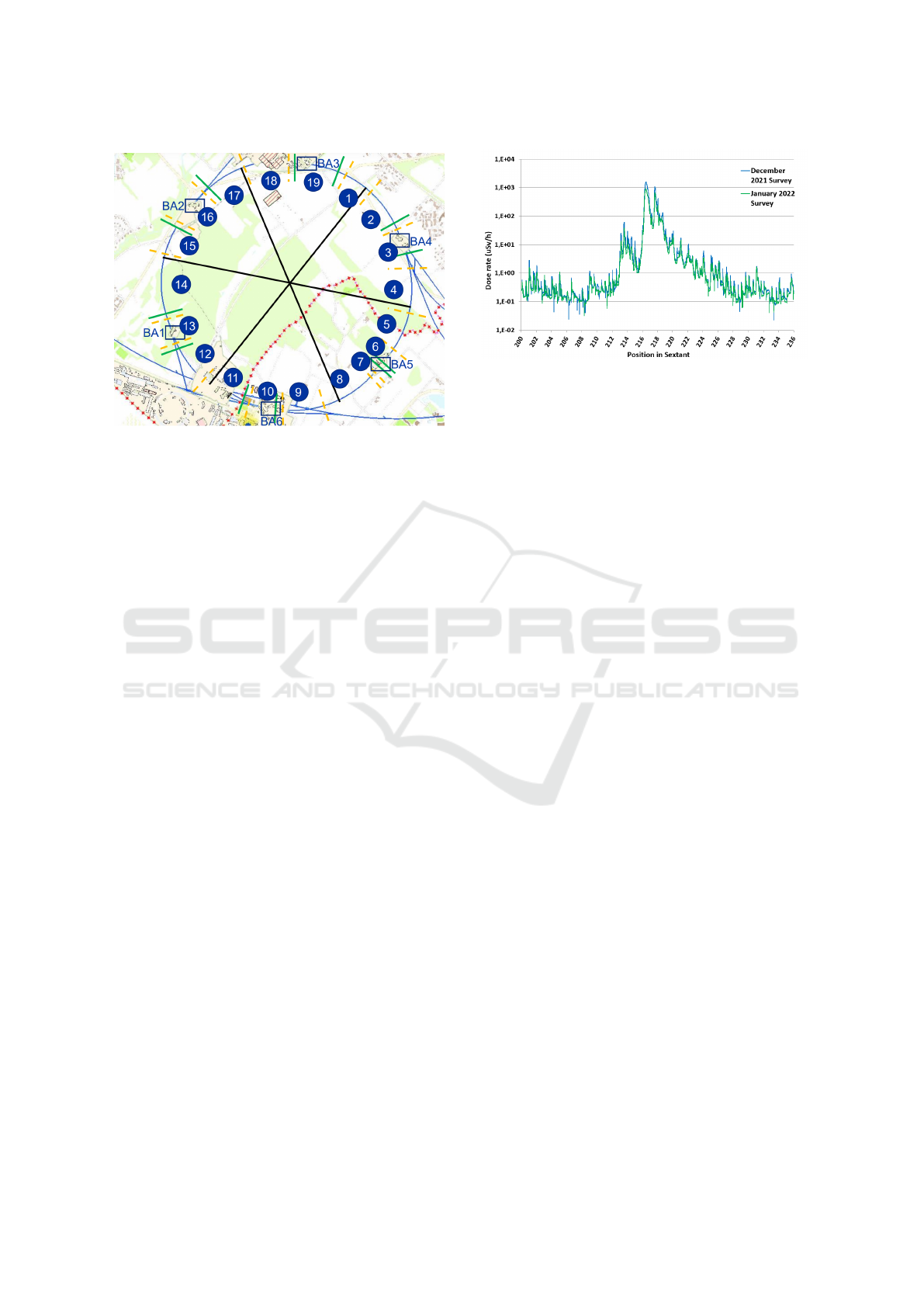
Figure 8: Data partitioning map of the SPS.
4.1.3 Data Treatment
The post processing of the data serves two main pur-
poses for this survey. On the one hand, the map-
ping between the position of the measurement and the
measured value must be carried out, including the cor-
rection of the positioning error, and on the other hand,
modifications are made to optimize the visualization
of the results. The odometry data of the robot base
provides the distance travelled or the so-called ”dis-
tance cumul
´
ee (DCUM)”, which approximates the
circumference of the SPS. As can be seen in Figure
8, the SPS is divided into 6 sextants. Within these
60° sectors, the unit of arc minutes is used for pre-
cise positioning. The dashed yellow elements along
the circumference of the SPS represent the position
of the secure gates. The 19 individual measurements
are then merged into 6 sextant data sets.
The unit of the radiation measurements is micro
Sievert per hour. In addition to these adjustments, the
position error of the measurement is corrected. This
is necessary due to the fact that mecanum wheels tend
to slip during acceleration and deceleration, which
means that the registered traveled distance is higher
than the real value. However, since the exact location
of the security doors is known, the position error can
be subsequently compensated by homogeneously ap-
plying the absolute percentage error to the measured
odometry in one segment run.
4.2 Results of the Robotic Radiation
Protection Survey
In Figure 9 the results from the December 2021/Jan-
uary 2022 robotic RP surveys in Sextant 2 of the SPS
are shown:
Figure 9: Robotic radiation survey results December 2021 /
January 2021 realized in sector 2 of the SPS.
The graph has a clear similarity to the 2008/2009
survey presented in section 1.2 . The increased mea-
suring frequency of the radiation sensor of 50 Hz re-
sults in an overall lower noise level. In direct com-
parison to Figure 1 , slightly higher radiation doses
were recorded than in the manual procedure. The rea-
son for this lies in the optimized positioning of the
radiation sensor on the robot arm at the level of the
beam axis, as well as a constant distance of the robot
towards the magnets of the SPS. A total of approx-
imately 500,000 data points were recorded in each
of the two teleoperated surveys, which roughly cor-
responds to one measurement point every 14 mm.
5 CONCLUSION AND OUTLOOK
In summary, it can be concluded that a complete
robotic solution has been developed, which allows the
radiation survey to be carried out in a teleoperated
manner. In particular, the absence of personnel in the
tunnel of the SPS during the survey is the main advan-
tage of this system. Consequently, the radiation dose
of the staff, which carries out the survey in person un-
der the current terms, can be saved. Moreover, the
functional advantage of more precise measurements
due to optimized conditions is also a significant ad-
vancement. The next major change is the construction
of a second identical robot including an additional
charging station. This change provides more flexibil-
ity in the execution of the survey. For instance, the
operation time in the tunnel can be reduced to half if
each robot covers 3 sextants and switches to the op-
posing charging station at the end of the operation.
The greatest potential of the project develop-
ment lies in the gradual autonomization of the robot.
Whereas at the current stage the operator’s attention
is indispensable for the execution of the task, the goal
for the future development will be to increase the as-
Telerobotic Radiation Protection Tasks in the Super Proton Synchrotron using Mobile Robots
457

sistance level so that the operator’s workload is pro-
gressively reduced until only potential intervention is
required. The first step of gradual autonomization
describes an assisted operation (Florian Petit, 2020).
All repetitive tasks are performed automatically. In
this case, the robot arm poses for achieving the park-
ing position, operation pose or even the folding pro-
cedure as shown in Figure 6 will be performed au-
tonomously. Furthermore, safety strategies concern-
ing collisions or communication loss are being imple-
mented. Level 2 describes an autopilot that is capable
of independently performing certain tasks under op-
timal conditions. Applied to this project, this means
the autonomous navigation of the start to the end point
of the measurements, whereby more complicated pro-
cesses, such as crossing security gates and navigating
through environments with obstacles, will not be in-
cluded yet. Therefore the operator is required to mon-
itor the situation at all times. Level 3 describes a com-
pletely autonomous execution of all steps of the oper-
ation. The user is only informed in critical situations
and is also given a buffer time to react appropriately to
the situation. Thus, this stage of development would
include all tasks of the survey, from mission prepara-
tion, measurement acquisition and security gate cross-
ing to the successful completion of the survey and de-
activation of the robot. In addition, security strategies
will be developed to take effect in case of execution
errors and will either correct the problem itself or give
the user time to intervene.
REFERENCES
Alessandro Masi (2017). Train inspector monorail- tim,
url: https://cds.cern.ch/record/2260825/?ln=de (ac-
cessed 28.02.2022).
Castro, M. D., Tambutti, M. L. B., Ferre, M., Losito, R.,
Lunghi, G., and Masi, A. (2018). i-tim: A robotic sys-
tem for safety, measurements, inspection and main-
tenance in harsh environments. In 2018 IEEE Inter-
national Symposium on Safety, Security, and Rescue
Robotics, SSRR 2018, Philadelphia, PA, USA, August
6-8, 2018, pages 1–6. IEEE.
Catherall, R., Andreazza, W., Breitenfeldt, M., Dorsival, A.,
Focker, G., Gharsa, T., Giles, T., Grenard, J.-L., Locci,
F., Martins, P., Marzari, S., Schipper, J., Shornikov,
A., and Stora, T. (2017). The isolde facility. Journal
of Physics G: Nuclear and Particle Physics, 44.
CERN (2006). Code de s
´
ecurit
´
e safety code. CERN.
CERN (2022). Accelerators, url: https://home.cern/science/
accelerators (accessed 28.02.2022).
D. Forkel-Wirth, M. Silari (Editors) (2010). Radi-
ation protection group annual report 2009, url:
https://cds.cern.ch/record/2221663/files/annrep-rp-
2009.pdf (accessed 28.02.2022).
Di Castro, M., Ferre, M., and Masi, A. (2018). Cern-
tauro: A modular architecture for robotic inspection
and telemanipulation in harsh and semi-structured en-
vironments. IEEE Access, 6:37506–37522.
Florian Petit (2020). The next step in autonomous driving,
url: https://www.blickfeld.com/blog/the-next-step-in-
autonomous-driving (accessed 28.02.2022).
Forkel-Wirth, D., Roesler, S., Silari, M., Streit-Bianchi, M.,
Theis, C., Vincke, H., and Vincke, H. (2013). Radia-
tion protection at cern. CERN.
ICRP (1991). 1990 recommendations of the international
commission on radiological protection. icrp publica-
tion 60 (users edition). ICRP.
Kershaw, K., Feral, B., Grenard, J.-L., Feniet, T., De, S.,
Hazelaar-Bal, C., Bertone, C., and Ingo, R. (2013).
Remote inspection, measurement and handling for
maintenance and operation at cern. International
Journal of Advanced Robotic Systems, 10:1.
Kim, J.-H., Lee, J.-C., and Choi, Y.-R. (2014). Larob:
Laser-guided underwater mobile robot for reactor ves-
sel inspection. IEEE/ASME Transactions on Mecha-
tronics, 19:1–10.
Lunghi, G., Marin, R., Di Castro, M., Masi, A., and Sanz,
P. J. (2019). Multimodal human-robot interface for
accessible remote robotic interventions in hazardous
environments. IEEE Access, 7:127290–127319.
Michelle Starr (2022). Lunar rover discovers mys-
terious glass spheres on the far side of the
moon, url: https://www.sciencealert.com/the-moon-
has-glass-balls (accessed 28.02.2022).
Park, J., Kim, S., Kim, J., and Kim, S. (2010). Driving
control of mobile robot with mecanum wheel using
fuzzy inference system. In ICCAS 2010, pages 2519–
2523.
Pi, R., Cie
´
slak, P., Ridao, P., and Sanz, P. J. (2021). Twin-
bot: Autonomous underwater cooperative transporta-
tion. IEEE Access, 9:37668–37684.
Prados Sesmero, C., Buonocore, L. R., and Di Castro, M.
(2021). Omnidirectional robotic platform for surveil-
lance of particle accelerator environments with limited
space areas. Applied Sciences, 11(14).
Rubino, E. M., Centelles, D., Sales, J., Marti, J. V., Marin,
R., Sanz, P. J., and Alvares, A. J. (2017). Progressive
image compression and transmission with region of
interest in underwater robotics. In OCEANS 2017 -
Aberdeen, pages 1–9.
Veiga Almagro, C., Lunghi, G., Di Castro, M., Cen-
telles Beltran, D., Mar
´
ın Prades, R., Masi, A., and
Sanz, P. J. (2020). Cooperative and multimodal ca-
pabilities enhancement in the cerntauro human–robot
interface for hazardous and underwater scenarios. Ap-
plied Sciences, 10(17).
ICINCO 2022 - 19th International Conference on Informatics in Control, Automation and Robotics
458
