
Neuro-dynamic Control of an above Knee Prosthetic Leg
Zunaed Kibria
*
and Sesh Commuri
†
Electrical and Biomedical Department, University of Nevada - Reno, Reno, Nevada, U.S.A.
Keywords: Neuro-dynamic Control, Prosthetic Leg, Gait Asymmetry.
Abstract: The control of a prosthetic leg for above-knee amputees is fraught with several challenges. While the
dynamics of the knee-ankle system are complex and unknown, the control problem is exacerbated by the lack
of desired joint trajectories as they are dictated by the locomotion needs of the individual. Improper movement
of the knee and ankle joints can have serious implications for the safety of the user. Further, dissimilarities in
the gait of the amputated side and the intact side can result in gait abnormalities that result in increased
metabolic energy consumption and musculo-skeletal pains in the short term, and cardiovascular and other
health complications in the long term. In this paper, we propose a novel neuro-dynamic control strategy that
can guarantee stable control of the prosthetic limb while minimizing the gait asymmetry between the intact
and prosthetic limb. Further, the algorithm learns the unknown elements of the dynamics and adapts to the
changing locomotion needs of the individual. The efficacy of the proposed approach is demonstrated through
numerical simulations.
1 INTRODUCTION
Above knee amputation has lasting effect on the
ability of an individual to perform daily activities and
can result in adverse long term consequences to the
mental and physical health (Myers & Chauvin, 2021).
Therefore, a proper fitting and functioning prosthetic
device is essential to rehabilitate an amputee and
avoid post-surgical complications such as pressure
sores, arthritis, gait asymmetry and depression (Mai,
2012). In addition to providing adequate support to
the individual during stance, an ideal prosthetic
device should enable the individual to regain near-
natural gait. To accomplish this the device must be
able to ascertain the intent of the user and then
generate movement of the joints to address the
walking speed and the nature of terrain. Further, the
response must be in real-time and should ensure the
stability of the device and safety of the individual.
Many of the commercially available lower limb
prosthetic devices are passive, cannot adapt to
changing gait requirements of the individual, and use
extra metabolism energy during locomotion (Bhat et
al., 2018; Versluys et al.). Computer-controlled
powered prosthetic devices can address some of the
requirements however, they cannot ascertain the
*
https://www.linkedin.com/in/zunaed-kibria-984743107/
†
https://www.unr.edu/ebme/people/sesh-commuri
intent of the user. Currently available powered
prosthetic legs are heavy and their control mechanism
is not sophisticated enough to support all daily
activities (Fleming, 2021). Some researchers
developed spring-based powered limbs to improve
the performance of these devices (Bhat et al., 2018;
Carney, 2020). But these powered limbs cannot be
used for a long term as they are unable to compensate
for the unknown dynamics (Carney, 2021). There are
some model reference adaptive control approaches
but these approaches are based on linearized model
and their performance deteriorates rapidly outside a
small region of operation (Pagel, 2017).
Several companies such as Ossur, Ottobock,
SpringActive, BionX Medical Technologies,
Freedom Innovations etc., have commercialized
active powered limbs (Windrich, 2016). Though
these devices provide good performance in terms of
locomotion, they use traditional control techniques
based on linear approximations of the system and are
unable to compensate for unmodeled dynamics.
Further, the control parameters of these devices have
to be adjusted to address the requiremnents of each
individual. Several researchers explored the use of
neural networks and reinforcement learning to control
artificial knee and ankle joint with varying degrees of
Kibria, Z. and Commuri, S.
Neuro-dynamic Control of an above Knee Prosthetic Leg.
DOI: 10.5220/0011268200003271
In Proceedings of the 19th International Conference on Informatics in Control, Automation and Robotics (ICINCO 2022), pages 29-37
ISBN: 978-989-758-585-2; ISSN: 2184-2809
Copyright
c
2022 by SCITEPRESS – Science and Technology Publications, Lda. All rights reserved
29

success (Mai & Commuri, 2016; Stolyarov, 2021;
Wen, 2017). However, these approaches ignore the
coupled dynamics between the knee and the ankle
thereby limiting the performance of these devices.
While the primary function of a lower-limb
prothesis is to provide support during stance, the
ability to provide near-natural gait is essential to the
long-term health of the individual. Asymmetric gait
can cause individuals to expend more metabolic
energy (Ryan et al., 2020). Asymmetric gait can also
lead to serious long-term injuries and poor quality of
life (Pirker, 2017). Impaired gait in the elderly can
lead to dementia and other neurological diseases
(Mielke et al., 2012). Therefore, it is desirable for a
prosthetic device to reduce gait asymmetry between
the intact and amputated side of an individual.
Design of a control system for above-knee
prosthesis is difficult for following reasons:
Ideal joint displacement profiles cannot be
specified prior to locomotion because it depends
on the intent of the indivisual.
During a gait cycle the knee and ankle joints are
affected by dynamical coupling of the prosthetic
leg system and residual hip.
Ground reaction force is proportional to the
body weight of a person and provides the
necessary propulsion for the gait (Perry, 2010).
While walking, lower limb joints are influenced
by ground reaction force which in turn affects
the knee and ankle joints in the form of
disturbance torque. Uncompensated disturbaces
will degrade the performance of the controller.
Neuro-dynamic programming (NDP) has shown
promising results in the control of uncertain complex
dynamical systems (Bugeja, 2008; Lu et al., 2008;
Mahmud et al., 2021). NDP is based on
approximation theory and neural networks and uses
Bellman’s optimality principle to improve the control
decision at each step to result in lower long term cost
(Bertsekas, 1995). However, traditional optimal
control had limited success in the control of prosthetic
leg (Chen et al., 2020; Rigatos, 2017).
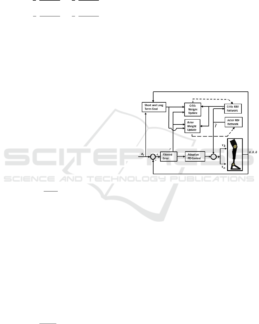
In this paper, we implement a neuro-dynamic
control approach for above-knee prosthetic system to
reduce gait asymmetry and achieve near natural gait.
The controller action is two-fold: At a lower level, a
filtered tracking error system ensures that the joints
follow the prescribed dipslacement profile. At a
higher level, the Critic Network computes the “to go”
cost and modifies the control action to minimize the
long-term cost. As a result, the performance of the
controller improves after each step, i.e., after each
stance phase of the gait. For this approach to be
successful, desired displacement profiles for the knee
and the ankle are first selected using gait information
from the intact side of the individual. A filtered
tracking error system generates the control torque that
enables the knee and ankle joints to track the
prescribed trajectories. A neural network is used to
learn the unknown dynamics of the system. After
each stance phase the “look ahead” costs are
computed and the wieghts of the critic network are
updated to minimize the costs. Simulation results
demonstrate that the knee and ankle joints as well as
the angle the foot makes with the ground track the
corresponding profiles on the intact side, thereby
improving stance and reducing assymetry.
The rest of the paper is organized as follows - a
dynamical model of the prosthetic system is
developed in section 2. In section 3, the modeling of
kinematic profiles and ground reaction force is
described. The design and detailed formulations of
the proposed controller are provided in section 4. The
stability of the proposed approach and the efficacy in
reducing gait assymetry is demonstrated through
simulation results in section 5. Conclusions of the
proposed technique and scope of future work are
discussed in section
6.
2 DYNAMICAL MODEL
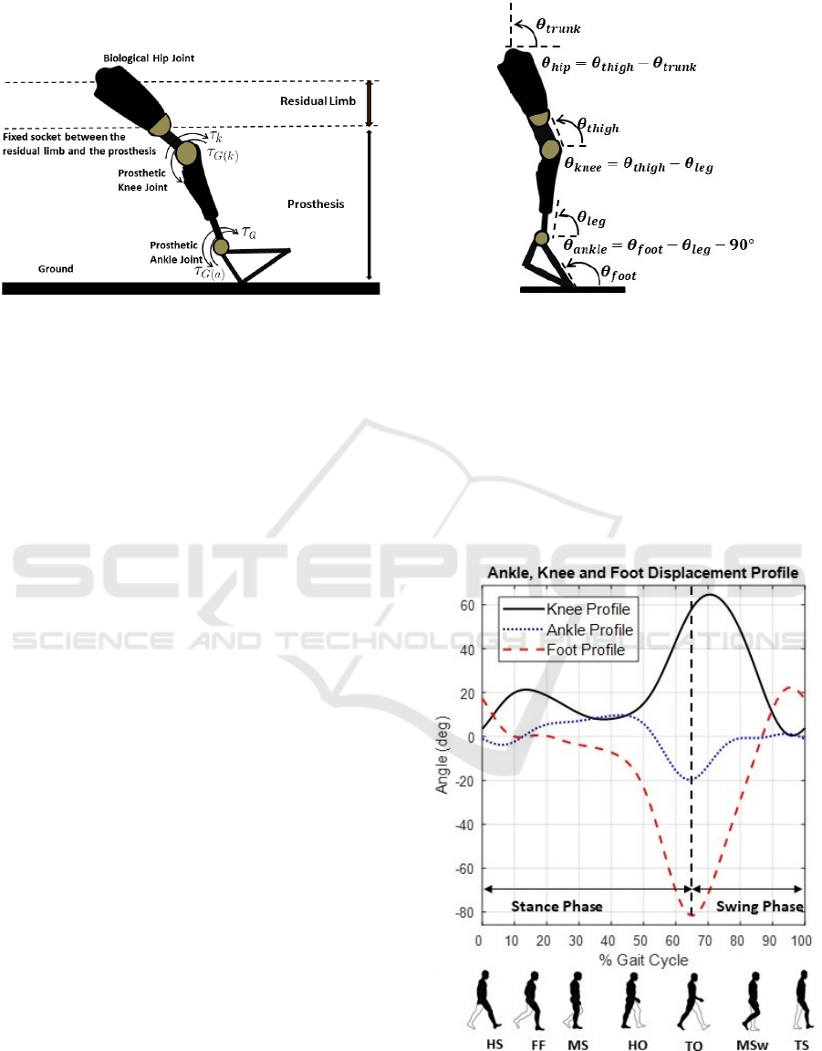
In this study, we examine the dynamics of a
transfemoral prosthesis used to improve the mobility
of an above knee amputee. The prosthetic device
comprises of a knee joint and an ankle joint connected
to the residual limb through a snug socket (Figure 1).
While the dynamics of such a device are complex, we
consider a simplified link segment representation of
residual limb (Figure 1) that captures the movement
in the sagittal plane (Mai & Commuri, 2016):
𝑀
𝜃
𝜃
𝑉
𝜃,𝜃
𝜃
𝐺
𝜃
𝐹
𝜃
𝜏
𝜏𝜏
(1)
where, ′𝑀
𝜃′ denotes the inertia matrix of the
coupled dynamics representing the knee-ankle
system, ′𝑉
𝜃,𝜃
′ stands for the Coriolis/ centripetal
matrix, ′𝐺
𝜃′ stands for the gravitational vector,
′𝐹
𝜃
′ represents the frictional terms, ′𝜏
′
represents the disturbance torque. On the right side of
equation (1), ′𝜏′ is a 2x1 dimensional vector that
represents the torque generated by each joint and ′𝜏
′
represents the ground reaction torque. ′𝜃′ and ′𝜃′
are
vector quantities that represent joint angles and
angular velocities. ′𝜃
′ represents angular acceleration.
ICINCO 2022 - 19th International Conference on Informatics in Control, Automation and Robotics
30
The details of the matrices in equation (1) are
given in the Appendix.
Figure 1: Link segment representation of the prosthetic leg.
Subscripts ‘k’ and ‘a’ denote quantities corresponding to
knee joint and ankle joint respectively.
3 KINEMATIC PROFILES AND
GROUND REACTION TORQUE
The inability to properly coordinate the movement of
the knee and ankle joints during locomotion can lead
to several musculoskeletal and neurological disorders
over time (Ranavolo, 2012). Therefore, the knee and
ankle joints of a prosthetic leg must function in
coordination to ensure the long-term health of the
individual. Further, the position of the foot during gait
is related to the instantaneous displacement of these
joints. The movement of the prosthetic foot has to be
nearly identical to that of the intact foot during
corresponding instants in gait in order to reduce the
asymmetry between the intact and amputated sides of
the individual.
The first step in the design of a controller is to
determine the desired displacement profiles for the
knee and ankle joints. This is problematic as these
displacement profiles are dependent on the intent of
the user and the terrain and are unknown at the time
of control. For example, walking at slow pace versus
walking at a brisk pace results in different
displacement profiles of these two joints.
In this paper we explore the use of nominal gait
profiles that can be parameterized and used to study
the gait of an individual over a variety of walking
speeds. Considering the knee and ankle joints of an
individual as shown in Figure 2, the nominal gait
profile can be studied by dividing the gait into stance
and swing phases (Figure 3). In the stance phase, the
foot is in contact with the ground and supports the
weight of the body. As the foot progresses from the
stance to the swing phase, the weight of the body is
Figure 2: Prosthetic leg joints angles.
transferred to the other foot. The stance phase starts
with ‘Heel Strike’ when the foot comes in contact
with the ground. As the stance progresses to ‘Foot
flat’ and ‘Mid stance’ subphases, more of the body
weight is supported by the foot. After ‘Heel-Off’ and
‘Toe-Off’ subphases the leg enters into the swing
phase and the body weight shifts to the opposite leg.
The nominal gait profiles for knee and ankle joints
and foot position relative to the ground is given in
Figure 3.
Figure 3: Nominal gait profiles for knee, ankle joints and
foot position relative to the ground; HS = Heel Strike, FF=
Foot Flat, MS = Mid Swing, HO = Heel off, TO = Toe Off,
MSW = Mid Swing, TS = Terminal Swing.
Neuro-dynamic Control of an above Knee Prosthetic Leg
31

Ground reaction torques acting on the leg joints
are a direct consequence of ground reaction force.
Ground reaction force (GRF) is the counter force of
the ground to human body during a gait. Ground
reaction force (GRF) is proportional to body weight
and transferred up to the leg joints and results in
proportional torques. To maintain a stable forward
dynamics during a gait, ground reaction force needs
to be accounted as an external force acting on the
system (Peasgood et al., 2006). GRF is typically
evaluated in a loboratory setting using force plates. It
is difficult to measure GRF outside a motion
laboratory because of the lack of force plates to
measure GRF (Recinos et al., 2020). In this paper, we
estimate the ground reaction force and torque into the
knee and ankle joints with following equations
(Millard, 2008):
𝐹
𝑘
𝑧
𝑆𝑡𝑒𝑝𝑦,0,0,𝑑
,𝑐
𝑧
𝐹
µ 𝐹
𝑠𝑔𝑛𝑣
𝜏
𝑑
𝐹
𝑑
𝐹
(2)
where, the vertical and horizontal force components
on the joints are denoted as ′𝐹
′ and ′𝐹
′. ′𝑧
′ and ′𝑧
′
are penetration and penetration rate of the foot, ‘𝑘
’,
‘µ’, ‘𝑠𝑝𝑒’ are spring coefficient, friction coefficient
and spring exponent. ′𝑑
′, ′𝑐
′ are maximal
damping penetration and maximal damping
coefficient. ‘𝑣
’ is the horizontal velocity of the
contact point relative to the ground. ‘𝜏
’ stands for
the ground reaction torque. ‘𝑑
’ and ‘𝑑
’ are the
vertical and horizontal distances of the joints with
respect to the foot-ground contact point.
To develop a control system to generate
appropriate torque for the knee and ankle joints, we
parameterize the nominal gait profiles and ground
reaction torques. Gait profiles and ground reaction
torques are approximated with following Fourier
equations:
𝜃
𝑡
𝑎
𝑎
cos𝜔𝑡 𝑏
sin𝜔𝑡
(3)
𝜏
𝑡
𝑐
𝑐
cos𝜔𝑡 𝑑
sin𝜔𝑡
(4)
where, ′𝜔′ is the angular velocity of the joint angles
at ‘t’ instance. ′𝑎
′, ′𝑐
′, ′𝑎
′, ‘𝑏
′, ′𝑐
′, ′𝑑
′ can be
found out using curve fitting algorithm (Mai, 2013).
4 CONTROLLER DESIGN
To design a controller to track the gait profiles shown
in Figure 3, we first define the tracking error vector
‘e’ and its derivative ‘e’ as follows:
𝑒𝜃
𝜃
𝑒 𝜃
𝜃
(5)
where, 𝜃
𝜃
𝜃
; 𝜃
𝜃
𝜃
;
′𝜃
′, ′𝜃
′, ′𝜃
′, ′𝜃
′ are desired angular positions
and velocities for knee and ankle joints. The dynsmics
of the system in equation (1) can be represented using
the filtered tracking error ‘r’ as
𝑟𝑒𝜆𝑒
(6)
where, 𝑟 is a 2x1 dimensional vector and 𝜆 > 0 is a
design parameter. Using equation (5), we can
represent the dynamics of the prosthetic system (1) as
𝑀
𝑟 𝑉
𝑟
𝑓
𝑥 𝜏 (7)
where, 𝑓𝑥 comprises the nonlinear terms of the
system.
f
x𝑀
𝜃
𝜆𝑒𝑉
𝜃
𝜆𝑒𝐹
𝐺
𝜏
𝜏
(8)
To estimate the nonlinear terms of the system, we
propose a neuro-dynamic control structure that will
learn the unknown dynamics of the system and
generate control input ‘𝜏’ that is applied to knee and
ankle joints to achieve a smooth gait and minimize
the long-term cost function. The control input to the
system is designed as:
𝜏
𝑓
x 𝐾
rυ
(9)
where, 𝑓
x is the estimation of fx, 𝐾
is design
parameter, r is the filtered tracking error, υ
ύsgnr is a robustifying term.
To design the proposed controller, heel strike
(HS) to heel strike (HS) instances have been
considered as one gait cycle. During one cycle, in
each instance we have defined the short-term costs for
knee joint and ankle joints as a function of their
tracking errors. The short-term cost function of the
prosthetic system is defined as 𝑆𝑡. 𝑆𝑡 is a 2x1
dimensional vector comprises knee and ankle joints’
cost functions 𝑆
and 𝑆
.
ICINCO 2022 - 19th International Conference on Informatics in Control, Automation and Robotics
32
𝑆𝑡
𝑆
𝑆
𝑆
𝑡
1
2
𝜃
𝜃
𝜃
1
2
𝜃
𝜃
𝜃
𝑆
𝑡
1
2
𝜃
𝜃
𝜃
1
2
𝜃
𝜃
𝜃
(10)
where 𝜃
, 𝜃
, 𝜃
, 𝜃
are desired angular positions
and velocities for knee and ankle joints. 𝜃
, 𝜃
, 𝜃
, 𝜃
are actual angular positions and velocities for knee
and ankle joints. 𝜃
, 𝜃
, 𝜃
, 𝜃
are the maximal
values for position and velocities for knee and ankle
joints.
To analyze the prolonged effect of the proposed
controller, the long-term cost of the system is
caluclated. Long term cost is defined as the
accumulated cost of the short time costs in equation
(10). Long term cost function for prosthetic system
can be represented as:
𝐿
𝑡
𝑆
𝑡1
𝛼𝑆
𝑡2
𝛼
𝑆
𝑡3
⋯
𝑆
𝑡1
𝛼𝐿
𝑡1
(11)
In which, 𝛼
0𝛼1
, is a discount factor and
S(t) is the short-term cost function.
The critic network generates ‘J(t)’ as an
approximation of the long-term cost function ‘L(t)’.
Approximation of long-term cost function is defined
with an RBF NN:
ℎ
𝑒𝑥𝑝
;
𝑗
1,2,3,4,…𝑘
𝐽
𝑡
W
h
𝑥
𝜀
(12)
where ‘𝑥
’ is the input to the network. ′𝜇
′, ′𝑏
′ is
the center and width of the gaussian of the neural net
‘k’. ‘W
’ represents the weight of the critic network
and ′𝜀′ is a very small value.
In this control structure, critic network inputs are:
𝑥
𝑒
𝑒
𝑒
𝑒
𝜃
𝜃
𝜃
𝜃
𝑓
𝑥
𝑓
𝑥
(13)
In which, 𝑒
,𝑒
,𝑒
,𝑒
are knee and ankle joints’
tracking errors and their derivatives. 𝜃
𝜃
𝜃
𝜃
are
knee and ankle joints’ calculated angles and
velocities. 𝑓
𝑥
,𝑓
𝑥
are non-linearities
estimation of knee and ankle joints by actor network.
Approximation of the non linearities is defined by
RBF NN:
ℎ
𝑒𝑥𝑝
;
𝑗
1,2,3,4,…𝑘
𝑓
𝑥
W
h
𝑥
𝜀
(14)
where ‘𝑥
’ is the input to the actor network. ′𝜇
′, ′𝑏
′
is the center and width of the gaussian of the neural
net ‘k’. ‘W
’ represents the weight of the actor
network and ′𝜀′ is a very small value.
The backpropagation error for critic network
′𝑒
′ is defined as:
𝑒
𝐽
𝑡1
𝑆
𝑡
𝛼𝐽𝑡 (15)
Update laws of the critic network are defined as:
W
αFh
r
κF
‖
e
‖
W
(16)
where ‘𝛼’ is the discount factor, and ‘F’ and ′κ′ are
design parameters. ‘r’, ‘e
’ are filtered tracking error
and critic network’s backpropagation error
respectively. Further, ‘h
’ for critic network can be
computed using (12).
Figure 4: NDP Control Structure for prosthetic leg.
With the help of the critic network, the actor
network updates itself to reduce the long-term cost
and approximate the nonlinearities of knee and ankle
joints. By learning the nonlinearities of the system, it
exerts proper torque to the knee and ankle joints for
smooth locomotion. To learn and estimate the non-
linearities with the actor network we use RBF
network mentioned in equation (12). Input to the actor
network are:
𝑥
𝑒
𝑒
𝑒
𝑒
𝜃
𝜃
𝜃
𝜃
𝜃
𝜃
(17)
Where, 𝑒
,𝑒
,𝑒
,𝑒
are knee and ankle joints’
tracking errors and their derivatives.
𝜃
,𝜃
,𝜃
,𝜃
,𝜃
,𝜃
are knee and ankle joints’
calculated angles, velocities and accelerations.
The input law into the system is corrected by the
actor network to minimize the long-term cost
function. In order to find out a control goal which
reduce the infinite horizon long term system cost to
minimum possible value, we define an ultimate
control goal ‘U
c
(t)’. The ultimate control goal ‘U
c
(t)’
Neuro-dynamic Control of an above Knee Prosthetic Leg
33
= 0, which is the long-term cost approximation of
‘J(t)’.
Back propagation error for actor network is given
as follows:
𝑒
𝑈
𝑡
𝐽
𝑡 (18)
The tuning rule for actor network is given as:
W
Fh
r
κF
‖
e
‖
W
(19)
In which, ‘F’ and ‘κ’ are design parameters. ‘r’,
‘e
’ are filtered tracking error and actor network’s
backpropagation error respectively. ‘h
’ for actor
network can be computed using (14).
Theorem: The control law in equation (9) with the
actor and critic network weight update laws in
equation (16) and (19), ensures the tracking errors in
equation (5) will be ultimately bounded. Further, the
cumulative long-term cost will be bounded.
5 NUMERICAL EXAMPLE
In this section simulation results have been provided
to demonstrate proposed controller’s performance.
These simulation experiments were designed to study
the performance with respect to:
a) tracking the desired knee and ankle joint profiles,
b) estimation of the nonlinear terms in the dynamics,
c) orientation of the foot relative to the ground
during a gait,
d) adaptability to variable walking speed, and
e) robustness to measurement and actuator noises.
5.1 Experimental Setup
In order to study the performance of the proposed
control strategy, it is assumed that the prosthetic
device is fitted on a healthy male of height 1.78
meters and weighing 90.7 kilograms. Corresponding
gait data from a similar intact individual is first
collected and analyzed. In these simulation studies it
is assumed that the individual is walking in normal
cadence. Based on the cadence, nominal trajectories
for knee and ankle joints are then approximated using
parameterization of nominal gait data collected from
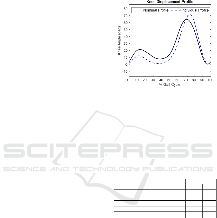
human subjects (Winter 2009). From Figure 5, it can
be seen that the approximate displacement profile for
the knee is close to the actual knee profile of an
individual.
Figure 5: Nominal and individual’s knee displacement
profiles.
Further, data in Table 1 shows that at each phase
of the gait, the approximate displacement profile is
within a small bound of the actual displacement
profile seen in a similar intact individual. Therefore,
in these simulation examples, the stance time is first
measured from the intact side and then used to
generate a desired displacement profiles using the
parametrization of naminal gait.
Table 1: Knee, Ankle and Foot angles for nominal and
individual’s gait profiles during stance phase. Nom. =
Nominal, Ind. = Individual. HS=Heel Strike, FF = Foot
Flat, MS = Mid Stance, HO = Heel Off, TO = Toe Off.
Gait
Ph.
Knee Angle Ankle Angle Foot Angle
Nom. Ind. Nom. Ind. Nom. Ind.
HS 3.48 1.47 -1.00 -4.67 17.35 7.68
FF 19.68 11.61 -2.46 1.64 0.00 1.05
MS 14.63 4.47 6.43 6.43 0.58 -1.09
HO 9.04 2.85 9.70 12.11 -9.99 -4.18
TO 58.39 62.69 -15.94 -6.84 -81.60 -71.19
5.2 Simulation Results
The parameters for model dynamics and design
values are given in the Appendix (Table 4-5). The
tracking performance of the knee and ankle joints and
foot position is shown in Figures (6-8). Figure 6
shows that the proposed NDP controller is able to
track the nominal knee and ankle profiles with very
little error. Actor network is able to accurately
estimate the non-linearities associate with knee and
ankle joints (Figure 7). As a result, the foot position
is maintained close to the desired position during
different gait phases. It is observed in Figure 8 that
the foot position in both stance and swing phase of the
ICINCO 2022 - 19th International Conference on Informatics in Control, Automation and Robotics
34
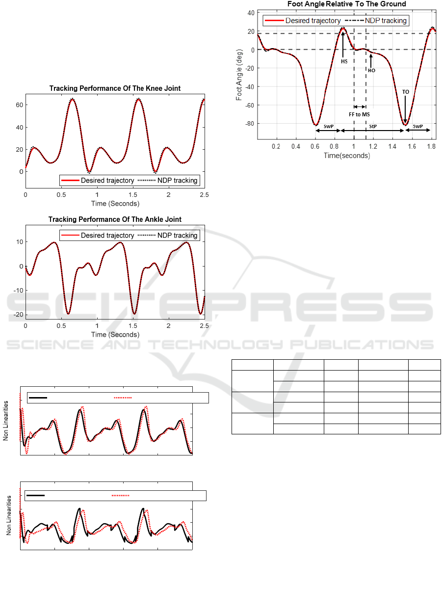
prosthesis is similar to that of an intact leg. Further
during the Foot Flat (FF) to Mid Stance (MS) phase,
the controller is able to maintain desired foot position
identical to an intact leg. This implies that the stance
on both intact and prosthetic side is similar leading to
the conclusion that the weight bearing is similar on
both sides.
Figure 6: Tracking performance of NDP for knee and ankle
joints.
Figure 7: Estimation of Nonlinearities for knee and ankle
joint.
Figure 8: Foot position of the prosthetic leg with NDP
controller. (HS=Heel Strike, FF = Foot Flat, MS = Mid
Stance, HO = Heel Off, TO = Toe Off, SwP = Swing Phase,
StP = Stance Phase).
To check the effect of variations in walking speed,
we calculate the long-term costs associated with knee
and ankle joints with the proposed control model. We
have tabulated the long-term cost for 3 steps with
medium, slow and fast cadence (Table 2). To
compare the proposed controller’s performance with
traditional PD and adaptive NN based controllers we
perform simulation with same set up and observe that
NDP based controller outperforms both PD and
Adaptive NN controllers (Table 2).
Table 2: Long-term cost for different walking cadence.
Gait Type Joint PD Adaptive NN NDP
Medium
Cadence
Ankle joint 1.05 0.4694 0.0082
Knee joint 5.05 1.3513 0.0083
Slow
Cadence
Ankle
j
oint 0.65 0.3728 0.0055
Knee
j
oint 5.59 0.9657 0.0055
Fast
Cadence
Ankle
j
oint 1.8698 0.6981 0.0984
Knee joint 6.0650 2.0096 0. 0985
To investigate the performance of the proposed
controller with noise, uniformly distributed
measurement and actuator noises are added into the
system. System is affected with 2% added
measurement noise to 𝜃 and 𝜃
and 20% actuator noise
to 𝜏. Considering the individual is walking in a
medium cadence, we analyze the long-term cost for
the proposed NDP, PD and Adaptive NN controllers
in noisy environment. It is observed from the
simulation results tabulated in Table 3 that NDP
based controller is less susceptible to added noise and
performs better than the rest controllers in terms of
long-term cost.
Knee Angle (deg)
Ankle Angle (deg)
00.511.522.5
Time (Seconds)
-10
0
10
20
30
40
Estimation of Knee Joint Non-Linearities with NDP
Actual non-linearities Estimated non-linearities
00.511.522.5
Time (Seconds)
-1
0
1
2
3
4
Estimation of Ankle Joint Non-Linearities with NDP
Actual non-linearities Estimated non-linearities
Neuro-dynamic Control of an above Knee Prosthetic Leg
35

Table 3: Long term cost with increasing measurement and
actuator noise.
Noise Join
t
PD Adaptive NN NDP
2% measurement
Noise
Ankle join
t
1.34 0.4845 0.0227
Knee join
t
5.5678 1.3868 0.0127
20% actuator
noise
Ankle join
t
1.2686 0.4917 0.0241
Knee join
t
5.2235 1.1219 0.0242
6 CONCLUSIONS
In this paper, a novel neuro-dynamic control
approach for above-knee prosthetic system was
developed to reduce gait asymmetry and achieve near
natural gait. Using a filtered tracking error system and
an actor-critic network, the controller was shown to
be able to track synthesised displacement profiles for
the knee and ankle joints while reducing the long-
term cost. As a result, the performance of the
controller improves after each step, i.e., after each
stance phase of the gait. Data collected in the lab
indicates that the synthesised gait profiles are close to
the knee and ankle displacements in an intact
individual while walking at self-selected pace.
Simulation results demonstrate that the knee and
ankle joints as well as the angle the foot makes with
the ground track the corresponding profiles on the
intact side, thereby improving stance and reducing
assymetry. In the future, the performance of the
controller will be verified on a prosthetic device
mounted on a gait simulator.
REFERENCES
Bertsekas, D. P. a. T. J. N. (1995). Neuro-dynamic
programming : an overview Proceedings of 1995 34th
IEEE Conference on Decision and Control, New
Orleans, LA, USA.
Bhat, S. G., Redkar, S., & Sugar, T. G. (2018).
Development of a Passive Prosthetic Ankle With Slope
Adapting Capabilities. ASME 2018 International
Mechanical Engineering Congress and Exposition,
Bugeja, M. K. a. F. S. G. (2008). Neuro-adaptive
dynamic control for mobile robots: Experimental
validation 2008 3rd International Symposium on
Communications, Control and Signal Processing, Saint
Julian's, Malta.
Carney, M. E. a. H. H. (2020). Electric-Energetic
Consequences of Springs in Lower-Extremity Powered
Prostheses on Varied Terrain 2020 8th IEEE
RAS/EMBS International Conference for Biomedical
Robotics and Biomechatronics (BioRob), New York,
NY, USA. 10.1109/BioRob49111.2020.9224458
Carney, M. E. a. S. T. a. S. R. a. D. J.-F. a. H. H. M. (2021).
Design and Preliminary Results of a Reaction Force
Series Elastic Actuator for Bionic Knee and Ankle
Prostheses. IEEE Transactions on Medical Robotics
and Bionics, 3(3), 542-553. https://doi.org/10.1109/
TMRB.2021.3098921
Chen, T., Babanin, A., Muhammad, A., Chapron, B., &
Chen, C. (2020). Modified Evolved Bat Algorithm of
Fuzzy Optimal Control for Complex Nonlinear
Systems. Romanian Journal Of Information Science
And Technology, 23, 28-40.
Fleming, A. a. H. S. a. B. E. a. H. F. a. H. H. H. (2021).
Direct continuous electromyographic control of a
powered prosthetic ankle for improved postural control
after guided physical training: A case study. Wearable
Technologies, 2, e3. https://doi.org/10.1017/wtc.2021.2
Lu, C., Si, J., & Xie, X. (2008). Direct heuristic dynamic
programming for damping oscillations in a large power
system. IEEE Transactions on Systems, Man, and
Cybernetics, Part B: Cybernetics, 38(4 ,), 1008--1013.
https://doi.org/10.1109/TSMCB.2008.923157
Mahmud, S. M. N., Nivison, S. A., Bell, Z. I., &
Kamalapurkar, R. (2021). Safe Model-Based
Reinforcement Learning for Systems With Parametric
Uncertainties [Original Research]. Frontiers in
Robotics and AI, 8.
https://doi.org/10.3389/frobt.2021.733104
Mai, A., & Commuri, S. (2016). Intelligent control of a
prosthetic ankle joint using gait recognition. Control
Engineering Practice, 49, 1-13. https://doi.org/10.10
16/j.conengprac.2016.01.004
Mai, A. a. C. S. (2013). Intelligent Control of a Prosthetic
Ankle Joint International Conference on Informatics in
Control, Automation and Robotics, https://www.
scitepress.org/Papers/2013/44856/pdf/index.html
Mai, A. a. C. S. a. D. C. P. a. D. J. a. E. W. J. J. a. R. J. L.
(2012). Effect of Prosthetic Foot on Residuum-Socket
Interface Pressure and Gait Characteristics in an
Otherwise Healthy Man With Transtibial
Osteomyoplastic Amputation. JPO: Journal of
Prosthetics and Orthotics, 24(4).
Mielke, M. M., Roberts, R. O., Savica, R., Cha, R.,
Drubach, D. I., Christianson, T., Petersen, R. C. (2012).
Assessing the Temporal Relationship Between
Cognition and Gait: Slow Gait Predicts Cognitive
Decline in the Mayo Clinic Study of Aging. The
Journals of Gerontology: Series A, 68(8), 929-937.
https://doi.org/10.1093/gerona/gls256
Millard, M. a. M. J. a. K. E. (2008). Multi-Step Forward
Dynamic Gait Simulation (Vol. 12).
https://doi.org/10.1007/978-1-4020-8829-2_2
Myers, M., & Chauvin, B. (2021). Above the Knee
Amputations. In. Florida: StatPearls Publishing.
P. (1996). Adjustments to Zatsiorsky-Seluyanov's segment
inertia parameters. Journal of Biomechanics, 29(9),
1223-1230. https://doi.org/https://doi.org/10.1016/00
21-9290(95)00178-6
Pagel, A. a. R. R. a. R. R. a. V. H. (2017). Bio-Inspired
Adaptive Control for Active Knee Exoprosthetics.
IEEE Transactions on Neural Systems and
Rehabilitation Engineering, 25(12), 2355-2364.
https://doi.org/10.1109/TNSRE.2017.2744987
ICINCO 2022 - 19th International Conference on Informatics in Control, Automation and Robotics
36

Peasgood, M., Kubica, E., & McPhee, J. (2006).
Stabilization of a Dynamic Walking Gait Simulation.
Journal of Computational and Nonlinear Dynamics,
2(1), 65-72. https://doi.org/10.1115/1.2389230
Perry, J. (2010). Gait Analysis: Normal and Pathological
Function. Journal of Sports Science \& Medicine, 9(2),
353-353.
Pirker, W. a. K. R. (2017). Gait disorders in adults and the
elderly. Wiener klinische Wochenschrift, 129(3), 81-95.
https://doi.org/10.1007/s00508-016-1096-4
Ranavolo, A. a. D. L. M. a. M. S. a. S. M. a. S. A. a. I. S. a.
C. E. a. A. R. a. P. A. (2012). Lower-Limb Joint
Coordination Pattern in Obese Subjects. BioMed
Research International.
Recinos, E., Abella, J., Riyaz, S., & Demircan, E. (2020).
Real-Time Vertical Ground Reaction Force Estimation
in a Unified Simulation Framework Using Inertial
Measurement Unit Sensors. Robotics, 9(4), 88.
Rigatos, G. a. S. P. a. S. D. a. P. R. E. (2017). Nonlinear
Optimal Control of Oxygen and Carbon Dioxide Levels
in Blood. Intelligent Industrial Systems, 3(2), 61-75.
https://doi.org/10.1007/s40903-016-0060-y
Ryan, H. P., Husted, C., & Lewek, M. D. (2020). Improving
Spatiotemporal Gait Asymmetry Has Limited
Functional Benefit for Individuals Poststroke. Journal
of Neurologic Physical Therapy, 44(3), 197-204.
https://doi.org/10.1097/npt.0000000000000321
Stolyarov, R. a. C. M. a. H. H. (2021). Accurate Heuristic
Terrain Prediction in Powered Lower-Limb Prostheses
Using Onboard Sensors. IEEE Transactions on
Biomedical Engineering, 68(2), 384-392.
https://doi.org/10.1109/TBME.2020.2994152
Versluys, R., Beyl, P., Damme, M. V., Desomer, A., Ham,
R. V., & Dirk, L. (2009). Prosthetic feet: State-of-the-
art review and the importance of mimicking human
ankle–foot biomechanics. Disability and
Rehabilitation: Assistive Technology, 4(2), 65-75 , year
= 2009. https://doi.org/10.1080/17483100802715092
Wen, Y. a. S. J. a. G. X. a. H. S. a. H. H. H. (2017). A New
Powered Lower Limb Prosthesis Control Framework
Based on Adaptive Dynamic Programming. IEEE
Transactions on Neural Networks and Learning
Systems, 28(9), 2215-2220. https://doi.org/10.1109/
TNNLS.2016.2584559
Windrich, M. a. G. M. a. C. O. a. R. S. a. B. P. (2016).
Active lower limb prosthetics: a systematic review of
design issues and solutions. BioMedical Engineering
OnLine, 15(3), 140. https://doi.org/10.1186/s12938-
016-0284-9
APPENDIX
Dynamics Matrices: 𝑀
𝜃
𝑀
,
𝑀
,
𝑀
,
𝑀
,
𝑀
,
𝑚
𝑚
𝑙
𝑚
𝑙
2𝑚
𝑙
𝑙
cos𝜃
𝑀
,
𝑀
,
𝑚
𝑙
𝑚
𝑙
𝑙
cos𝜃
𝑀
,
𝑚
𝑙
𝑉
𝜃,𝜃
𝑚
𝑙
𝑙
2𝜃
𝜃
𝜃
sin𝜃
𝑚
𝑙
𝑙
𝜃
sin𝜃
𝐺
𝜃
𝑚
𝑚
𝑔𝑙
cos𝜃
𝑚
𝑔𝑙
cos𝜃
𝜃
𝑚
𝑔𝑙
cos𝜃
𝜃
𝐹
𝜃𝜅
𝑠𝑔𝑛
𝜃
𝜃
𝜃
𝜃
; 𝜃
𝜃
𝜃
; 𝜃
𝜃
𝜃
.
𝜏
𝜏
𝜏
; 𝜏
𝜏
𝜏
; 𝜏
𝜏
𝜏
Subscripts ‘k’ and ‘a’ denotes knee and ankle joints
respectively.
Table 4: Plant parameters.
𝑚
𝐾𝑛𝑒𝑒 𝑡𝑜𝑎𝑛𝑘𝑙𝑒 𝑙𝑖𝑛𝑘𝑆ℎ𝑎𝑛𝑘 𝑚𝑎𝑠𝑠
3.16 kg
𝑚
𝐴𝑛𝑘𝑙𝑒 𝑎𝑛𝑑
𝑓
𝑜𝑜𝑡 𝑚𝑎𝑠𝑠
1.001 kg
𝑙
𝐾𝑛𝑒𝑒𝑡𝑜𝑎𝑛𝑘𝑙𝑒 𝑗𝑜𝑖𝑛𝑡 𝑙𝑒𝑛𝑔𝑡ℎ
0.07 m
𝑙
𝐴𝑛𝑘𝑙𝑒 𝑗𝑜𝑖𝑛𝑡 𝑡𝑜ℎ𝑒𝑒𝑙 𝑙𝑒𝑛𝑔𝑡ℎ
0.093 m
𝑔 𝐺𝑟𝑎𝑣𝑖𝑡𝑎𝑡𝑖𝑜𝑛𝑎𝑙 𝑎𝑐𝑐𝑒𝑙𝑒𝑟𝑎𝑡𝑖𝑜𝑛
9.8 ms-2
𝜅
𝐷𝑦𝑛𝑎𝑚𝑖𝑐𝐹𝑟𝑖𝑐𝑡𝑖𝑜𝑛 𝐶𝑜𝑒𝑓𝑓𝑖𝑐𝑖𝑒𝑛𝑡
0.2
Assuming that the individual is an average male
weighing 73.0 kilograms (kgs) and of height 1.741
meters (m), 𝑚
, 𝑚
, 𝑙
, 𝑙
are collected from (P,
1996)
Table 5: Design values.
𝜆𝐷𝑒𝑠𝑖𝑔𝑛 𝑝𝑎𝑟𝑎𝑚𝑒𝑡𝑒𝑟
6
𝐾
𝐷𝑒𝑠𝑖𝑔𝑛𝑝𝑎𝑟𝑎𝑚𝑒𝑡𝑒𝑟
4
ύ
𝐷𝑒𝑠𝑖𝑔𝑛 𝑃𝑎𝑟𝑎𝑚𝑒𝑡𝑒𝑟
0.3
𝛼 (Discount factor)
0.95
F (NN tuning gain)
22 0
0
22
κ (NN design parameter)
1
𝑘
(Spring coefficient to measure
GRF)
210
N𝑚
𝑆𝑝𝑒 (Spring exponent to measure
GRF)
2.2
µ
(Friction coefficient to measure
GRF
)
0.2
Network structure for actor and
critic
Input node: 10
Hidden layer: 30
Output layer: 2
Neuro-dynamic Control of an above Knee Prosthetic Leg
37
