Mutual Relative Localization in Heterogeneous Air-ground Robot Teams
Samet G
¨
uler
a
,
˙
I. Emre Yıldırım
b
and H. Halid Alabay
c
Dept. Electrical and Electronics Eng., Abdullah G
¨
ul University, Barbaros, Kayseri, 38080, Turkey
Keywords:
Heterogeneous Multi-robot Systems, Relative Localization, Bayesian Filtering.
Abstract:
Air and ground robots with distinct sensing characteristics can be combined in a team to accomplish de-
manding tasks robustly. A key challenge in such heterogeneous systems is the design of a local positioning
methodology where each robot estimates its location with respect to its neighbors. We propose a filtering-
based relative localization algorithm for air-ground teams composed of vertical-take-off-and-landing drones
and unmanned aerial vehicles. The team members interact through a sensing/communication mechanism rely-
ing on onboard units, which results in a mutual connection between the air and ground components. Exploiting
the supplementary features of omnidirectional distance sensors and monocular cameras, the framework can
function in all environments without fixed infrastructures. Various simulation and experiment results verify
the competency of our approach.
1 INTRODUCTION
Heterogeneous multi-robot systems (HMRS) offer
unparalleled advantages in various tasks which re-
quire a collection of distinct sensing and manipulation
capabilities such as area coverage, search and rescue,
collaborative transportation, and signal source local-
ization (Kushleyev et al., 2013; Staub et al., 2017;
Tokekar et al., 2016; Manyam et al., 2016; Grochol-
sky et al., 2006; Vidal et al., 2002; Yu et al., 2015).
In a HMRS, each individual robot acquires a local
sensory information from the environment with its
unique sensing capabilities. For instance, for a map-
ping objective, a set of aerial robots can collect vi-
sual representation of the environment while the lo-
cal occupancy properties can be sensed by a group of
ground robots. Then, the acquired data can be fused
online to build a unified map, improving the efficiency
and robustness compared to the homogeneous MRS
approaches (Li et al., 2016; Mueggler et al., 2014;
Kaslin et al., 2016).
Estimation of relative positions between team
members in a MRS has been an active research area
in the last decade. Traditional localization methods
for HMRS rely on the existence of infrastructures
which provide an absolute frame such as GPS and
motion capture (mocap) systems. Such approaches
lose validity in several real-life conditions, e.g., in
GNSS-denied environments or rooms without mocap
a
https://orcid.org/0000-0002-9870-166X
b
https://orcid.org/0000-0001-8035-0569
c
https://orcid.org/0000-0001-5360-3655
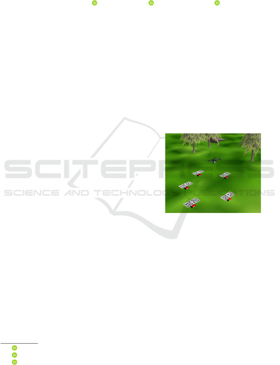
Figure 1: A sample heterogeneous team composed of five
UGVs and a drone.
systems. To remove this fundamental necessity, the
relative quantities between the team members should
be estimated with the onboard perception capabili-
ties. A common approach is to fuse distance sensors
with proprioceptive onboard sensors such as IMU
(Kia et al., 2016; Wallar et al., 2018; Prorok et al.,
2011; Hepp et al., 2016; Kim and Kim, 2013; Nguyen
et al., 2021). Since most distance sensors (e.g., ultra-
sonic and laser-based) provide one-directional mea-
surement data with limited FOV, a collection of those
sensors are implemented on the robots or in the en-
vironment to enlarge the operation zone of the robots
in a MRS (Kim and Kim, 2013). On the other hand,
ultrawideband (UWB) sensors offer unparalleled ad-
vantages in mobile robot localization thanks to their
omnidirectional distance measurement with high ac-
curacy and precision (Hepp et al., 2016; Wallar et al.,
2018). However, one may lose the observability of
304
Güler, S., Yıldırım,
˙
I. and Alabay, H.
Mutual Relative Localization in Heterogeneous Air-ground Robot Teams.
DOI: 10.5220/0011267800003271
In Proceedings of the 19th International Conference on Informatics in Control, Automation and Robotics (ICINCO 2022), pages 304-312
ISBN: 978-989-758-585-2; ISSN: 2184-2809
Copyright
c
2022 by SCITEPRESS – Science and Technology Publications, Lda. All rights reserved

the relative position with the distance only approaches
in leader-follower formations (van der Helm et al.,
2019).
Several works employed vision-based approach
for relative localization in MRSs. Early works in this
direction used tags with specific patterns mounted on
robots to discriminate the robots from the background
in camera images (Krajn
´
ık et al., 2014; Saska et al.,
2016; Roelofsen et al., 2015). With the recent devel-
opments in computer vision methods and computa-
tional units, the time required to detect sophisticated
object models has reduced significantly, which en-
abled onboard detection of drones with deep learn-
ing techniques (Vrba and Saska, 2020). Although
high detection rates for onboard drone detection using
convolutional neural network (CNN) methods are re-
ported in several tasks, the distance estimation mech-
anisms show poor performance with vision-only ap-
proaches. These results call for the need for an inte-
gration of the distance and vision sensors for reliable
relative localization.
We address the relative localization objective in an
air-ground team which consists of a team of drones
and unmanned ground vehicles (UGV). We develop
a filtering algorithm to estimate online the relative
positions between the UGVs by utilizing the percep-
tion feedback of the drones. Our algorithm relies
on the mutual interaction between the drone and the
UGVs, established by the robots’ onboard perception
and local inter-robot communication. Particularly, the
drones are commanded to hover around the desig-
nated locations on the UGV formation to provide the
UGVs with the bearing measurements required to per-
form estimation. We performed several simulations
and experiments with varying number of drones and
UGVs. The main contributions of the work are as fol-
lows. We propose a complete localization and co-
ordination framework for an air-ground robot team
by integrating the onboard distance and vision sens-
ing capabilities. Second, we propose a multi-rate ex-
tended Kalman filtering (EKF) algorithm which man-
ages three measurement cases which occur as a re-
sult of the varying formation geometry of the HMRS.
Finally, we illustrate several simulation and exper-
iment results for the externally commanded UGVs
case and formation control case. Our work differs
from the previous HMRS applications (Staub et al.,
2017; Tokekar et al., 2016; Grocholsky et al., 2006;
Manyam et al., 2016; Vidal et al., 2002; Yu et al.,
2015) in two aspects. First, the main objectives in the
aforementioned works are path planning, map build-
ing or target tracking objectives with several infras-
tructure aids. Since our ultimate goal is to build safe
and efficient swarms with arbitrary number of robots,
we aim at improving the situational awareness of the
robots in the swarm and focus on relative localization.
Second, we utilize communication and sensor fusion
by incorporating a visual sensor, UWB distance sen-
sors, and IMUs onboard of the robots for an improved
coordination between the air and ground entities. In
(Cognetti et al., 2014), a drone equipped with vision
sensors localizes a team of UGVs without any on-
board tags exploiting the vertical motion capability
of the drone. However, drones may lose tracking of
the UGVs in an operation. In our framework, UWB
sensors on board of the UGVs adds resiliency to the
HMRS by pursuing the localization when the drones
lose the UGVs in their image views.
The rest of the work is organized as follows. In
Section 2, we define the HMRS model and formulate
the localization problem. In Section 3, we propose
the filtering and motion control algorithms. Section 4
demonstrates the simulation and experimental results
as well as a discussion on the applications. Finally,
Section 5 concludes the work.
2 OBJECTIVE
We consider a heterogeneous multi-robot system
(HMRS) of N + M + 1 robots, comprised of N +
1 non-holonomic UGVs R
i
, i ∈ {0,...,N} and M
drones D
j
, j ∈ {1, ... ,M}. The robots are desired
to move in coordination to accomplish a given ob-
jective. We focus on the design of a practical coor-
dination mechanism between the robots. Designing
such mechanisms in the absence of an infrastructure
such as motion capture (mocap) systems remains a
big challenge. Our goal is to devise a scalable and ro-
bust localization algorithm for the swarm that enables
the realization of the typical practical distributed for-
mation control algorithms.
To realize such a scheme without the aid of a GPS
or mocap system, each robot should utilize its on-
board capabilities and achieve a certain level of sit-
uational awareness. We assume that each UGV R
i
is equipped with UWB sensors to acquire the inter-
UGV distance measurements. Consider the common
motion model for a non-holonomic UGV R
i
as fol-
lows:
p
i
k+1
= p
i
k
+
cos(θ
i
k
),sin(θ
i
k
)
>
v
i
k
T
s
, (1)
θ
i
k+1
= θ
i
k
+ ω
i
k
T
s
, (2)
where p
i
=
x
i
,y
i
>
∈ ℜ
2
is the 2D position, θ
i
is the
heading angle, v
i
,ω
i
are the linear and angular speed
commands of R
i
, i ∈ {0,. .., N}, k ∈ N
+
is the time
step, and T
s
is the sampling time constant.
Mutual Relative Localization in Heterogeneous Air-ground Robot Teams
305
We assume that each drone D
i
is equipped with a
monocular camera together with a flight control unit
for the low-level control. Assuming that the motion
in the roll and pitch axes are stabilized by the low-
level controller, we denote by ζ =
x
i
d
,y
i
d
,ψ
i
>
∈ ℜ
3
the state vector of a drone D
i
, where x
i
d
,y
i
d
are the 2D
coordinates and ψ
i
is the heading angle with respect
to a fixed frame F
G
.
Our main objective is to design a robust localiza-
tion algorithm for the system components such that
each robot will be able to estimate or receive by com-
munication the relative quantities required for a coor-
dinated motion. We define the localization objective
as follows. A UGV R
i
, i = (1,. .., N) should esti-
mate the relative positions r
i
to its neighbors defined
by an underlying constraint graph in the UGV team
in the fixed frame F
G
. Simultaneously, the drones
should move in coordination with the UGVs and pro-
vide them with a perspective view and absolute sensor
measurements to be used in the relative position esti-
mations. Therefore, we aim at designing a Bayesian
filtering algorithm and a formation control algorithm
for the UGVs so that they can estimate their relative
positions to their neighbors to move in coordination.
3 APPROACH
Our approach is divided in two parts below. First, we
design the localization algorithm for the UGVs stating
the assumptions on the drones’ motion. Second, we
present the drones’ formation control mechanisms.
3.1 Ground Robot Localization
We assign UGV R
0
as the leader which moves with
external commands or based on a path planning al-
gorithm. Typically, the leader UGV is equipped with
a better sensor suite than the other UGVs and deter-
mines suitable paths or waypoints for the entire team.
For instance, it can build a collision-free path for the
team with an onboard LIDAR sensor by assuming the
entire team constructs a disc with certain radius. Not-
ing that various path planning algorithms can be inte-
grated, we focus on the design of our relative local-
ization framework below.
Each follower UGV, R
i
, i ∈ {1,..., N}, uses the
inter-robot distance measurements and the feedback
signal received from the drones D
i
to estimate its rel-
ative position r
i
towards R
0
. Assuming that all UGVs
move on a 2D plane, we define the relative position
system model between R
0
and R
i
, i ∈ {1,..., N}, as
follows:
x
i
k+1
= x
i
k
+
u
3
k
cos(x
4
k
) − u
1
k
cos(x
3
k
)
u
3
k
sin(x
4
k
) − u
1
k
sin(x
3
k
)
u
2
k
u
4
k
T
s
, (3)
where x
i
=
(r
i
)
>
,θ
i
,θ
0
>
is the state vector, u =
v
i
,ω
i
,v
0
,ω
0
>
is the input vector for the two-robot
system
{
R
0
,R
i
}
, and r
i
=
r
i
x
,r
i
y
>
∈ ℜ
2
is the rela-
tive position seen by R
i
in the fixed frame F
G
.
Furthermore, the objective of a drone
D
j
, j ∈ {1,...,M}, is to detect and follow the
pair {R
0
,R
i
} where i ∈ {1, ...,N} (Fig. 2).
Drone D
j
changes the index i in its leader
list {R
0
,R
i
} with a certain time period such as
({R
0
,R
1
},{R
0
,R
2
},. .., {R
0
,R
N−1
},{R
0
,R
1
},. ..)
based on a schedule which will be designed in
Section 3.2. During an operation, all drones fly with
a fixed heading in the fixed frame F
G
, i.e., ψ
i
k
=
¯
ψ
for some arbitrary constant
¯
ψ. Thus, the constant
orientation of the drones serves as the absolute
coordinate frame provider for the entire MRS. That
is, the x − y plane of the drone’s body coordinate
frame is utilized as the global frame. To maintain
the constant heading during an operation, the drones
may utilize their onboard magnetometers or a set
of patterns in the environment. For instance, if the
team is intended to operate in a certain environment
with low magnetic deviation, the drones may trust
their magnetometers which are available in most
commercial flight control units.
Denote the bearing angles between R
0
and R
i
, i ∈
{1,..., N}, by φ
i
= atan(r
i
y
,r
i
x
). A drone D
i
aims at
calculating and broadcasting the bearing angles φ
i
and
heading angles θ
i
of the UGVs. For this purpose, the
ground robots are equipped with certain patterns over-
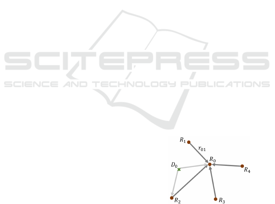
Figure 2: The proposed localization graph among a team of
five UGVs and a drone projected onto a 2D plane. UGV
R
0
serves as the leader for the team while each of the other
UGVs R
i
, i ∈ {1,...,N}, acts as the first follower and de-
tects and estimates their relative positions toward R
0
. Each
drone D
j
, j ∈ {1,..., M}, acts as the second follower and
estimates its relative positions toward R
0
and a follower
R
i
, i ∈ {1, ..., N} at any time.
ICINCO 2022 - 19th International Conference on Informatics in Control, Automation and Robotics
306

head, e.g., qr code, so that their heading and bear-
ing angles can be acquired by the drone’s camera
(Fig. 1). For convenience, drone D
i
is assumed to
fly at a sufficiently high altitude ¯z so that it can de-
tect a pair of robots {R
0
,R
i
} by its camera. Such a
suitable margin for ¯z can be found empirically. More-
over, each follower UGV R
i
, i ∈ {1,...,N}, measures
the distances d
0i
= kr
i
k and the inter-UGV distances
d
ij
= kr
i j
k = kp
i
− p
j
k from the onboard UWB sen-
sors. Therefore, the observed variables are the dis-
tances d
0i
, the heading angles θ
i
, and the bearing an-
gles φ
i
.
To estimate r
i
by robot R
i
, i ∈ (1,...,N), we use
a multi-rate EKF algorithm with three measurement
models. Based on the availability of the measure-
ments broadcast by drone D
i
, robot R
i
performs the
update stage using one of the following models:
y
i
=
d
0i
,φ
i
,θ
i
,θ
0
>
, if sw = 1
d
0i
,
¯
φ
i
,θ
0
>
, if sw = 2
d
0i
, if sw = 3
(4)
where the switching signal sw denotes the drone’s
measurement mode. Denote the set of the pairs of
UGVs detected by the drones at any time instant by
S =
{
.. .{R
0
,R
i
}. ..
}
, i ∈ {1, ...,N}. Then, the mea-
surement model of UGV R
i
, i ∈ {1,..., N}, at that
time instant is determined based on the following
rules:
• (sw=1) If {R
0
,R
i
} ∈ S , we set sw = i, which im-
plies the bearing φ
i
is measured. Thus, the de-
tected robot R
i
uses the first measurement model
which includes the distance d
0i
and bearing φ
i
to-
ward R
0
, the self heading θ
i
, and the heading θ
0
of R
0
.
• (sw=2) If {R
0
,R
i
} /∈ S and S 6=
/
0, the UGV
R
i
uses the second measurement model where
the bearing
¯
φ
i
toward R
0
is calculated artifi-
cially by using the formation geometry as fol-
lows. Consider Fig. 3 where two UGVs R
j
,R
i
follow a leader UGV R
0
. Denote the internal
angles formed by the triangles T
R
0
,R
j
,R
i
and
T
R
0
,R
i
,R
j
by α
1
and α
2
, respectively. By as-
sumption, we exclude the collinear robots case,
thus α
1
,α
2
are well-defined. If {R
0
,R
j
} ∈ S and
thus β
j
is measured at a given time instant, then
the bearing angle β
i
for all robots R
i
,i 6= j that
are on the right half plane of the line l
i
(the green-
shaded area in Fig. 3) can be calculated as follows:
β
i
= β
j
+ π − α
1
− α
2
,
where
α
1
= arctan(
q
1 − γ
2
,γ), γ =
d
2
0j
+ d
2
ij
− d
2
0i
2d
0j
d
ij
.
Figure 3: Calculation of the bearing angles for the UGVs
not detected by the drones.
Similarly, α
2
can be calculated. Likewise, the
bearing angles which lie on the left-half-plane
of the line l
i
can be calculated using the same
method.
• (sw=3) If S ≡
/
0, i.e., none of the drones can
see a UGV pair {R
0
,R
i
} for any i ∈ {1, ...,N},
then all drones broadcast a Null message, mean-
ing that all UGVs perform the iteration with the
third measurement model by using the UWB dis-
tances only.
A pseudocode for the estimation algorithm of
robot R
i
is given in Algorithm 1. This algorithm har-
monizes the sensing, communication, and filtering ca-
pabilities of the robots. To summarize, each UGV
performs the usual EKF prediction step followed by
the selection of the measurement model at the time
instant k which determines the update step. Particu-
larly, the linearized measurement model matrix is up-
dated based on the measurement model of the UGV.
We omit the details of the EKF algorithm for the sake
of space, which can be found in (Thrun et al., 2005).
In the proposed system, each UGV R
i
estimates its
relative position to R
0
independently. In this sense,
our application differs from the collaborative local-
ization in which all team members update the same
state vector estimate in a centralized manner.
Algorithm 1: EKF for robot R
i
.
Require: Previous state and covariance estimate
Ensure: Current state and covariance estimate
1: Prediction step
2: if Measurement model 1 then
3: y
k
=
d
0i
k
,φ
i
k
,θ
i
k
,θ
0
k
4: else if Measurement model 2 then
5: y
k
=
d
0i
k
,
¯
φ
i
k
,θ
0
k
6: else if Measurement model 3 then
7: y
k
= d
0i
k
8: end if
9: Update step
10:
ˆ
x
k
← New state estimate
11: Σ
k
← New covariance estimate
Mutual Relative Localization in Heterogeneous Air-ground Robot Teams
307
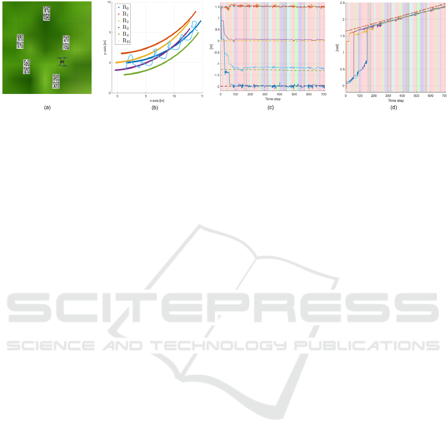
Figure 4: (a) A top view of the simulation setup; (b) traces of the robots; (c) relative position estimate; (d) heading angle
estimations.
3.2 Drone Localization and Control
Each drone D
j
, j ∈ {1,..., M} estimates its planar po-
sition with respect to the UGVs by using its onboard
camera sensor. As the second follower in the un-
derlying graph, a drone D
j
aims at hovering on the
midpoints m
i
between the pair of UGVs {R
0
,R
i
}, i ∈
{1,..., N} with respect to the following schedule. At
the initial time step k = 0, the drones are commanded
to track the midpoints m
1
,m
2
,. .., m
M
. To provide ev-
ery R
i
with its bearing toward R
0
, it is desired to visit
all midpoints m
i
, i ∈ {1,...,N} periodically by the
drones. We denote the time spent at a midpoint by
k
m
and set it as a design constant. Therefore, at the
time instants k = bk
m
, b ∈ N
+
, the drones switch their
commanded midpoints to m
b+1
,m
b+2
,. .., m
b+M
until
N = b+ M, where N is the total number of the UGVs.
When N = b + M + 1, the commanded midpoints for
the drones is switched back to m
1
,m
2
,. .., m
M
.
When hovering on the midpoints m
i
, the drones
uses computer vision techniques to detect the spe-
cial patterns on the UGVs. When the drone detects
a pair {R
0
,R
i
}, it calculates and broadcasts the head-
ing angles θ
0
,θ
i
and the bearing angle φ
i
and sets
the parameter sw accordingly. Remarkably, since the
drone maintains a constant heading
¯
ψ during an oper-
ation, the bearing angle φ
i
is calculated with respect
to
¯
ψ which serves as the absolute north for the entire
team. Furthermore, the drones use the desired forma-
tion geometry to calculate the control signal required
to move between the midpoints. In the next section,
we apply the typical proportional controller to control
the drones’ motions on the horizontal plane, noting
that more advanced control algorithms can be applied
to control the drones’ motions with higher precision.
4 RESULTS
We evaluated the proposed framework both in simula-
tions and real experiments. We aimed at demonstrat-
ing the applicability of the framework and its integra-
tion into formation control algorithms.
4.1 Simulations
We used a Gazebo environment including Rosbot
UGVs and Iris drones integrated to the ROS inter-
face. We mounted two qr code patterns on each
Rosbot to be able to detect its heading angle by a
mono camera attached at the bottom of the drone.
The UGVs were accepting linear and angular veloc-
ity inputs and placed in a hexagon formation with
the leader (R
0
) in the front (Fig. 4a). Each follower
UGV performed relative position estimation indepen-
dently obeying the state and observation models given
in Section 3.1. The drone implemented the px4 soft-
ware which accept the high-level planar velocity and
yaw commands by handling the low-level control. All
robots ran their estimation code at 20 Hz. We ac-
quired the inter-UGV distances from the simulation
model, emulating the UWB distance measurements.
We show the traces of the robots and the relative
position and heading estimation results of a simula-
tion in Fig. 4. In this simulation, the UGVs moved
on an arc with constant linear and angular veloci-
ties, and the drone followed the midpoints periodi-
cally for t
m
= 8 seconds per robot with the sequence
(m
4
,m
1
,m
2
,m
3
,m
4
,. ..) by utilizing a custom control
algorithm. In Fig. 4b and Fig. 4c, the green back-
ground shows the time instants where the drone ob-
serves the pair {R
0
,R
1
}, the blue background for
{R
0
,R
2
}, the black background for {R
0
,R
3
}, and the
cyan background for {R
0
,R
4
}. The UGV R
4
cor-
rected its relative position estimation to the leader
(green colored robot) successfully when the drone de-
tected the robot pair {R
0
,R
4
} and broadcast φ
4
at
the start of the operation (Fig. 4c). Meanwhile, the
other UGVs R
1
,R
2
, and R
3
calculated their bearing
angles φ
1
,φ
2
, and φ
3
, respectively, by using the for-
mation geometry (as given in Section 3.1) and cor-
rected their relative position estimations accordingly.
ICINCO 2022 - 19th International Conference on Informatics in Control, Automation and Robotics
308
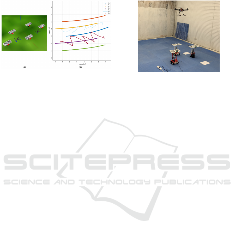
Figure 5: (a) A simulation setup with two drones; (b) Paths
of the robots in an arc motion test.
On the other hand, every follower UGV corrects its
own heading estimation once the drone visits its cor-
responding midpoint (Fig. 4d). The main reason for
the undetected time zones (red background) was the
switching motion of the drone between the midpoints.
Remarkably, although the total time without UGV de-
tection was almost half of the simulation time, the
framework showed high performance in estimating
the actual relative positions.
Next, we used two drones and five UGVs in 11
simulations to demonstrate the scalability of our ap-
proach (Fig. 5). The first drone is assigned to de-
tect the UGVs R
0
,R
1
, and R
2
, and the second drone
aims at detecting the UGVs R
0
,R
3
, and R
4
. The fol-
lower UGVs R
i
, i ∈ {1, ...,4}, used the EKF outcome
to maintain their desired relative positions toward the
leader R
0
in a hexagon formation. We define the esti-
mation root mean square errors (RMSE) by
e
j
i
=
"
1
K
K
∑
k=1
ˆ
r
i j
k
− r
i j
k
2
#
1
2
, (5)
where K is the total time steps during an experi-
ment,
ˆ
r
i
1
,
ˆ
r
i
2
are the relative pose estimations of the
ith UGV’s EKF for the x and y axes, respectively,
with j ≡ {x,y} denoting the coordinate axis. We ob-
served that e
j
i
remained below 0.1 meters for all i, j
in all tests. We did not observe significant perfor-
mance variation with the change in the drone’s fol-
low time t
m
. Compared to the first set of simulations,
the lower estimation errors stemmed from the fact that
each drone is responsible for two UGVs, which in-
creased the time duration spent on top of each UGV.
4.2 Experiments
The experimental setup consisted of a custom-built
drone with an F450 frame and three non-holonomic
UGVs (two Rosbots and a Turtlebot) (Fig. 6). A Ros-
bot was assigned as the leader (R
0
), and the other
Figure 6: The experimental setup consisted of a custom-
built drone of diameter 45cm equipped with a Pixhawk
flight controller together with two Rosbot and a Turtlebot
UGVs.
UGVs were to estimate the relative positions r
1
,r
2
.
Each UGV was equipped with calibrated Decawave
ultrawideband distance sensors at the center and two
qr code patterns on the top. A Raspberry Pi4 with
a camera performed UGV detection and high-level
computations on the drone while the low-level con-
trol was handled by a Pixhawk 4 flight controller.
We collected the ground truth position data and con-
trolled the drone’s low-level motion with a Vicon mo-
tion capture system. We used the traditional com-
puter vision techniques and packages to detect the
qr code patterns. We observed that the camera de-
tected reliably the patterns at the distance interval
1.4 < h < 1.85 meters, and thus we flew the drone
at the altitude h = 1.75 m.
In the first set of experiments, the UGVs were
steered with exogenous velocity commands, and the
drone was controlled to follow the midpoints m
1
,m
2
.
An experiment’s result is given in Fig. 7 where the
UGVs followed a straight path with v
i
= 0.05 m/s and
ω
i
= 0 rad/s. The drone was commanded to follow
each midpoint for t
m
= 4 seconds before switching
to the other midpoint. In Fig. 7b and Fig. 7c, the
green background shows the time instants where the
drone observes both R
0
and R
1
, the blue background
for both R
0
and R
2
, and the black background for
all R
0
,R
1
and R
2
. Finally, the light red background
shows that the drone cannot detect any UGV. Once
the drone detected the pair {R
0
,R
1
} for the first time
(the first green time instant), the EKF of UGV R
1
uses
the first measurement model in (4) which corresponds
to the locally observable instant, and the correct rela-
tive position and heading
ˆ
θ
1
are estimated. However,
ˆ
θ
2
could not be estimated until the drone could detect
the heading of R
2
at the time step 400 (the first time
instant the blue background is seen in Fig. 7d). No-
tably, this time instant corresponds to the unobserv-
able mode, which we aim at studying in our future
Mutual Relative Localization in Heterogeneous Air-ground Robot Teams
309
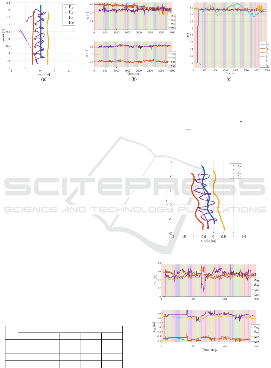
Figure 7: Results of an experiment with externally commanded UGVs: (a) Traces of the robots; (b) relative position estimates
ˆ
r
1
,
ˆ
r
2
; (c) heading angle estimations
ˆ
θ
i
. Background color codes: Green: {R
0
,R
1
} detected; Blue: {R
0
,R
2
} detected; Black:
{R
0
,R
1
,R
2
} detected; Red: No pair detected.
works. We emphasize that the relative position and
heading estimations were initiated far from their cor-
rect values in this experiment. Nevertheless, the fil-
ter succeeded to approach the correct values. Table 1
shows the RMSE for the relative position estimations
(5) in five experiments. We observed that the aver-
age error remained below 0.16 meters in all experi-
ments. We note that the drone’s high-level controller
was tuned to follow smoothly the midpoints m
1
,m
2
.
In the second set of experiments, we used the per-
ception layer output as feedback to a formation con-
trol layer. Particularly, the follower UGVs tried to
maintain the desired relative positions r
des
1
,r
des
2
to-
ward the leader R
0
by using the estimation outcomes
ˆ
r
1
,
ˆ
r
2
. We illustrate a formation control experiment in
Fig. 8 and Fig. 9 where R
1
and R
2
use custom con-
trol algorithms to maintain the desired relative poses
r
des
1
= [0.5,0.5]
>
,r
des
2
= [−0.5,0.5]
>
m toward the
leader R
0
which is commanded externally to follow an
S-shaped path. Similar to the previous case, the drone
was controlled to switch between the midpoints m
1
and m
2
. We observed that the estimation performance
sufficed to maintain the desired formation as long as
the drone tracks the midpoints smoothly. We provide
further insights and a detailed discussion in the next
part.
In Fig 10, we show the RMSE for the formation
errors in eight experiments, which are defined as fol-
Table 1: Relative position estimation RMSEs of five exper-
iments in meters.
Experiment No
1 2 3 4 5
e
x
1
0.133 0.132 0.135 0.104 0.157
e
y
1
0.099 0.188 0.115 0.089 0.137
e
x
2
0.109 0.098 0.105 0.106 0.135
e
y
2
0.110 0.191 0.115 0.120 0.155
lows:
f
i, j
=
"
1
K
K
∑
k=1
r
i j
k
− r
i j,des
2
#
1
2
,
where K is the total time steps during an experiment,
i is the follower UGV identity, and j ≡ {x,y} denotes
Figure 8: Traces of the robots in a formation control exper-
iment.
Figure 9: Relative position estimates
ˆ
r
1
,
ˆ
r
2
in a for-
mation control experiment. Background color codes:
Green: {R
0
,R
1
} detected; Blue: {R
0
,R
2
} detected; Black:
{R
0
,R
1
,R
2
} detected; Red: No pair detected.
ICINCO 2022 - 19th International Conference on Informatics in Control, Automation and Robotics
310
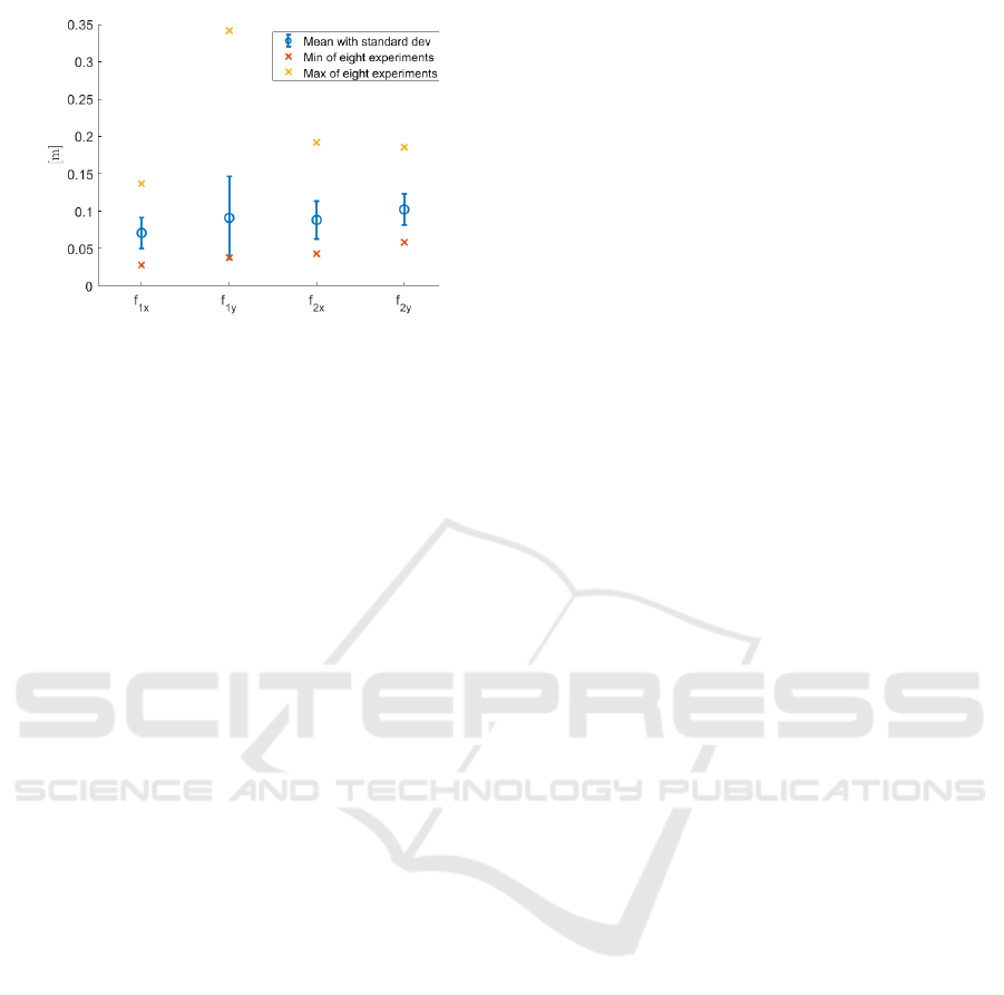
Figure 10: RMSE of eight formation control experiments.
the coordinate axis. Although we did not observe a
direct correlation between the error levels and the co-
ordinate axes or robots’ identities, we observed that
the average error in each axis remained below 0.12
meters, which proves the efficiency of the proposed
method.
We emphasize the unique difficulty of the relative
localization problem in a HMRS, particularly when
combined with a formation control algorithm. In con-
trast to the traditional localization objective where a
set of anchors located at known locations serve as bea-
cons to find the location of a group of tag sensors, rel-
ative localization systems try to generate hypothesis
in the absence of an anchor. For this reason, the rel-
ative position estimators usually cannot generate cen-
timeter level accuracy as in the case of the traditional
estimators (Vrba and Saska, 2020). Nevertheless, we
observed satisfactory results both in the localization
and formation control simulations and experiments.
To overcome the issue of deviating drones due
to unobserved patterns, we developed a custom con-
trol algorithm for the UGVs that make use of the
leader velocity, which proved useful when the forma-
tion moved on arcs. In our primary tests, the drone
tended to deviate from the midpoints of the UGV
pairs, which we overcame by designing a control law
for the drone that utilized the single UGV detection as
well. Therefore, we emphasize that a designer should
fine tune the drone controller before implementing the
proposed framework.
5 CONCLUSIONS AND FUTURE
WORK
We have addressed the relative localization in het-
erogeneous multi-robot systems, a key challenge for
the realization of such systems in a variety of ap-
plications. We have proposed a Bayesian filter
which estimates the relative positions among the
UGVs in certain configurations by utilizing their on-
board sensing and communication mechanisms to-
gether with the drones’ perception. We have demon-
strated through simulations and experiments that the
proposed method yields sufficient estimation perfor-
mance under the case of intermittent perception feed-
back acquired from the aerial vehicle. A comprehen-
sive set of simulations and experiments have proven
that the estimation outcome yield sufficient accuracy
for the formation maintenance without external in-
frastructures.
Future work may include a realization of the pro-
posed model with more UGVs and drones both in-
doors and outdoors. Also, a more robust control algo-
rithm design for the drone can improve the estimation
performance. Furthermore, we aim at carrying out
a detailed observation analysis for the system model
to investigate the observable and unobservable modes
for the varying cases of drone detection.
ACKNOWLEDGEMENTS
This paper has been produced benefiting from
the 2232 International Fellowship for Outstanding
Researchers Program of T
¨
UB
˙
ITAK (Project No:
118C348). However, the entire responsibility of the
paper belongs to the owner of the paper. The financial
support received from T
¨
UB
˙
ITAK does not mean that
the content of the publication is approved in a scien-
tific sense by T
¨
UB
˙
ITAK.
REFERENCES
Cognetti, M., Oriolo, G., Peliti, P., Rosa, L., and Stegagno,
P. (2014). Cooperative control of a heterogeneous
multi-robot system based on relative localization. In
2014 IEEE/RSJ International Conference on Intelli-
gent Robots and Systems. IEEE.
Grocholsky, B., Keller, J., Kumar, V., and Pappas, G.
(2006). Cooperative air and ground surveillance.
IEEE Robotics & Automation Magazine, 13(3):16–25.
Hepp, B., N
¨
ageli, T., and Hilliges, O. (2016). Omni-
directional person tracking on a flying robot using
occlusion-robust ultra-wideband signals. In 2016
IEEE/RSJ International Conference on Intelligent
Robots and Systems (IROS), pages 189–194.
Kaslin, R., Fankhauser, P., Stumm, E., Taylor, Z., Mueg-
gler, E., Delmerico, J., Scaramuzza, D., Siegwart, R.,
and Hutter, M. (2016). Collaborative localization of
aerial and ground robots through elevation maps. In
2016 IEEE International Symposium on Safety, Secu-
rity, and Rescue Robotics (SSRR). IEEE.
Mutual Relative Localization in Heterogeneous Air-ground Robot Teams
311

Kia, S. S., Rounds, S., and Martinez, S. (2016). Coopera-
tive localization for mobile agents: A recursive decen-
tralized algorithm based on kalman-filter decoupling.
IEEE Control Systems, 36(2):86–101.
Kim, S. J. and Kim, B. K. (2013). Dynamic ultra-
sonic hybrid localization system for indoor mobile
robots. IEEE Transactions on Industrial Electronics,
60(10):4562–4573.
Krajn
´
ık, T., Nitsche, M., Faigl, J., Van
ˇ
ek, P., Saska, M.,
P
ˇ
reu
ˇ
cil, L., Duckett, T., and Mejail, M. (2014). A
practical multirobot localization system. Journal of
Intelligent & Robotic Systems, 76(3-4):539–562.
Kushleyev, A., Mellinger, D., Powers, C., and Kumar, V.
(2013). Towards a swarm of agile micro quadrotors.
Autonomous Robots, 35(4):287–300.
Li, J., Deng, G., Luo, C., Lin, Q., Yan, Q., and Ming,
Z. (2016). A hybrid path planning method in un-
manned air/ground vehicle (UAV/UGV) cooperative
systems. IEEE Transactions on Vehicular Technology,
65(12):9585–9596.
Manyam, S. G., Casbeer, D. W., and Sundar, K. (2016). Path
planning for cooperative routing of air-ground vehi-
cles. In 2016 American Control Conference (ACC).
IEEE.
Mueggler, E., Faessler, M., Fontana, F., and Scaramuzza,
D. (2014). Aerial-guided navigation of a ground
robot among movable obstacles. In 2014 IEEE Inter-
national Symposium on Safety, Security, and Rescue
Robotics (2014), pages 1–8.
Nguyen, T. H., Nguyen, T.-M., and Xie, L. (2021). Range-
focused fusion of camera-IMU-UWB for accurate and
drift-reduced localization. IEEE Robotics and Au-
tomation Letters, 6(2):1678–1685.
Prorok, A., Tom
´
e, P., and Martinoli, A. (2011). Accom-
modation of nlos for ultra-wideband tdoa localization
in single- and multi-robot systems. In 2011 Interna-
tional Conference on Indoor Positioning and Indoor
Navigation, pages 1–9.
Roelofsen, S., Gillet, D., and Martinoli, A. (2015). Recipro-
cal collision avoidance for quadrotors using on-board
visual detection. IEEE.
Saska, M., Baca, T., Thomas, J., Chudoba, J., Preucil,
L., Krajnik, T., Faigl, J., Loianno, G., and Kumar,
V. (2016). System for deployment of groups of un-
manned micro aerial vehicles in GPS-denied environ-
ments using onboard visual relative localization. Au-
tonomous Robots, 41(4):919–944.
Staub, N., Mohammadi, M., Bicego, D., Prattichizzo, D.,
and Franchi, A. (2017). Towards robotic MAGMaS:
Multiple aerial-ground manipulator systems. In 2017
IEEE International Conference on Robotics and Au-
tomation (ICRA). IEEE.
Thrun, S., Burgard, W., and Fox, D. (2005). Probabilistic
Robotics. MIT press.
Tokekar, P., Hook, J. V., Mulla, D., and Isler, V. (2016).
Sensor planning for a symbiotic UAV and UGV sys-
tem for precision agriculture. IEEE Transactions on
Robotics, 32(6):1498–1511.
van der Helm, S., Coppola, M., McGuire, K. N., and
de Croon, G. C. H. E. (2019). On-board range-based
relative localization for micro air vehicles in indoor
leader–follower flight. Autonomous Robots, 44(3-
4):415–441.
Vidal, R., Shakernia, O., Kim, H., Shim, D., and Sastry, S.
(2002). Probabilistic pursuit-evasion games: theory,
implementation, and experimental evaluation. IEEE
Transactions on Robotics and Automation, 18(5):662–
669.
Vrba, M. and Saska, M. (2020). Marker-less micro aerial
vehicle detection and localization using convolutional
neural networks. IEEE Robotics and Automation Let-
ters, 5(2):2459–2466.
Wallar, A., Araki, B., Chang, R., Alonso-Mora, J., and Rus,
D. (2018). Foresight: Remote sensing for autonomous
vehicles using a small unmanned aerial vehicle. In
Hutter, M. and Siegwart, R., editors, Field and Ser-
vice Robotics, pages 591–604, Cham. Springer Inter-
national Publishing.
Yu, H., Meier, K., Argyle, M., and Beard, R. W. (2015).
Cooperative path planning for target tracking in ur-
ban environments using unmanned air and ground ve-
hicles. IEEE/ASME Transactions on Mechatronics,
20(2):541–552.
ICINCO 2022 - 19th International Conference on Informatics in Control, Automation and Robotics
312
