
Shore based Control Center Architecture for Teleoperation of Highly
Automated Inland Waterway Vessels in Urban Environments
Arne Lamm
1a
, Janusz A. Piotrowski
2b
and Axel Hahn
1c
1
Institute of Systems Engineering for Future Mobility, DLR e.V., Oldenburg, Germany
2
Department of Computing Science, Carl von Ossietzky Universität Oldenburg, Oldenburg, Germany
Keywords: Shore based Control Center, Remote Control, Situational Awareness, Autonomous Shipping, Inland
Waterways.
Abstract: The following paper presents an SCC architecture that allows to take over the remote control of one or more
ships from the shore side, especially in critical situations, in order to present a concrete solution of a remote
control center as proposed in the MASS levels for autonomous navigation. Particular attention was paid to
the technical and functional components and requirements specified by the regulations, and the practicability
based on decision-making and action execution was investigated. In particular, the three levels of situational
awareness were taken into account and the remote control center was finally implemented as a prototype. For
the evaluation, the practicability based on the RTT was assessed and the completeness based on the design
specifications of common INS was examined.
1 INTRODUCTION
In the context of automation in the maritime domain,
remote control is also increasingly important as a
fallback solution for such systems. Furthermore,
different approaches address the remote control as a
pre-step of autonomous vessels or as fallback system
for unexpected situations that cannot be handled.
With this understanding the term remote control
covers both the direct control of the remote-controlled
ship and the instruction of an autonomous system that
controls and steers the ship. This remote control
should be provided by a shore-based control center
(SCC), which combines all necessary components for
a stable and reliable remote control. Such an SCC can
be governed by, for example authorities or authorized
operators (IMO, 2018). Further, more than one
institution could operate their own SCCs, where for
example the shipping company as well as the
government have own SCCs, which are used to
monitor, control, or ensure the correct and legal
operating of a ship. Especially when shipping
companies are regarded, the ability of controlling
more than one ship is required (MacKinnon et al.,
a
https://orcid.org/0000-0002-8815-3444
b
https://orcid.org/0000-0001-8934-7040
c
https://orcid.org/0000-0003-2240-5351
2015). But when remote control is considered, not
only the control itself, but also the situation awareness
of the remote operator and the communication
between the SCC and the ship needs to be considered
(Dittmann et al., 2021). The situation awareness
addresses the environment perception as well as the
internal state of the ship. This situation awareness is
provided by using different sensors which are located
onboard. While the perception sensors are used to
measure the environment, detect target ships,
obstacles and ship specific metrics like speed and
course. The internal state sensors are used to measure
different information about the internal state of the
ship like the propulsion system or about the cargo.
Derived from this, the SCC should include the
capability of providing a situation awareness and
control functionality, to the remote operator.
Especially regarding these functions, the Vessel
Traffic Service (VTS) at the first impression has
similar capabilities. The VTS is a service, which is
provided in areas with high traffic, where the VTS
uses globally available perception sensor information
as well as information from the crew and is authorized
to control, manage, and support navigational tasks.
Lamm, A., Piotrowski, J. and Hahn, A.
Shore based Control Center Architecture for Teleoperation of Highly Automated Inland Waterway Vessels in Urban Environments.
DOI: 10.5220/0011266000003271
In Proceedings of the 19th International Conference on Informatics in Control, Automation and Robotics (ICINCO 2022), pages 17-28
ISBN: 978-989-758-585-2; ISSN: 2184-2809
Copyright
c
2022 by SCITEPRESS – Science and Technology Publications, Lda. All rights reserved
17

The difference between the VTS and the SCC is, that
the SCC has all internal and perception information
from the ship (Dittmann et al., 2021). So, the SCC
employee is in an extended understanding a part of
the crew (not located onboard), while the VTS is an
external authority. Further, a VTS has the ambition to
have a macroscopic view of certain situations and
areas whereas an SCC has a more microscopic view
of the traffic situation, in particular the view from one
of the involved vessels within a specific (encounter)
situation.
This description shows the need for an SCC that
provides both the control function and situational
awareness for the remote operator. Furthermore, the
SCC need to embed into an overall architecture that
enables the remote control and monitoring for several
parties.
This paper provides a generic architecture, which
enables different parties to remote control and
monitor one or more ships, by ensuring the remote
control as well as all needed information for situation
awareness. Chapter 2 describes the current state of
remote control and SCCs in the research domain. This
is followed by the detailed definition of situation
awareness and their levels, as well as the remote-
control functionality. After this the concept for a SCC
architecture is presented. In the evaluation the test
setup is described, and the delay of control commands
are evaluated, followed by the architecture evaluation
based on use cases from the AVATAR research
project, where the architecture was applied within
physical maritime testbed environment called
eMaritime Reference Platform (eMIR).
2 RELATED WORK
In the context of remote control and SCCs different
approaches exist, which differs in scope and
functionality. In particular, the various approaches
focus either on remote control and situational
awareness or on SCC. In the following, remote
control will be discussed first, followed by situational
awareness, and then SCC.
2.1 Remote-control and Situation
Awareness
Two approaches can be distinguished when
considering remote control. One is the control of an
autonomous system, and the other is the direct control
of a ship. Zhang & Zhang (2021) design a power and
remote-control system for monitoring ships in lakes
and reservoirs. The remote-control was designed to
steer the vessel directly by the operator. In contrast,
Son et al. (2004) design an operational control and
monitoring system for small unmanned observation
ships (UOV). The system was designed to instruct the
autonomous system on the UOV by sending
navigational and control data. In addition, there also
exist approaches which combine both, the control of
an autonomous system as well as the direct control.
The following approaches include both control
possibilities. Dittmann et al. (2021) present an
approach for remote-control, using the international
regulations of watch-keeping. In their approach the
remote control is provided by an autonomous
supervisor, which can be instructed from the remote-
control-center. Stateczny & Burdziakowski (2019)
present an overall architecture for small unmanned
surface vessels (USV), where they show the modules
of the USV accordingly to (IMO, 2018). They show
the hardware architecture with all modules which are
needed on the USV. Furthermore, they present the
software architecture which include the control and
monitoring of the USV. In this architecture the USV
is controlled by a mission control system, which is
already controlled by the autonomous system and can
be overwritten by the control mode. Furthermore, the
remote-control can instruct the autonomous system as
well as the mission control system. A second
architecture, which support the controlling of the
autonomous system onboard as well as the direct
control, was presented by Guo et al. (2015). The
authors design the remote control with two different
set of commands. The first set contains commands to
send waypoints, or a start and destination point for the
autonomous system. The second set include
commands where propulsion parts can be steered
directly from the remote operator.
The situation awareness, as second part, can be
considered from two different viewpoints. The first
viewpoint from the remote-control perspective and
the second from the SCC perspective. Zhang & Zhang
(2021), Stateczny & Burdziakowski (2019) and Guo
et al. (2015) determined internal sensor readings and
condition of the systems as data which need to be
provided to the remote operator. In contrast the
MUNIN project, which has developed a technical
concept for operation of unmanned merchant ship
(Fraunhofer CML, 2016), determined the ECDIS,
should be provided for situation awareness for the
remote operator in addition to the temporal overview
and the internal ship conditions as the main data
(Porathe, 2014). Where the ECDIS, by providing the
same functionality as onboard, include at least the
perception sensors. Further in some situations
additional data can be used, including a camera
ICINCO 2022 - 19th International Conference on Informatics in Control, Automation and Robotics
18

system (Porathe et al., 2014). Dittmann et al. (2021)
determined the voyage information (including
waypoints), the navigational information including
for example weather, position, speed, and distance to
next waypoint. Further the object detection from the
autonomous system, dynamic information, safety and
emergency, propulsion system status, cargo and
stability have been identified as relevant information
for situation awareness.
2.2 (Shore based) Control Centers
Control centers are basically stations from which
remote control can be performed. The concept itself
is location-independent and can also be located within
direct sight of the remotely controlled object. The
SCC is a special control center, which is located on
shore and out of sight of the ship. Most approaches
address the location-independent remote-control-
center, like Zhang & Zhang (2021), Son et al. (2004),
Stateczny & Burdziakowski (2019) and Guo et al.
(2015). While the MUNIN project design a SCC,
which is able to control the vessel from a static
location (Fraunhofer CML, 2016). But the remote-
control stations in their project are basically used for
monitoring and instructing the vessels, while the parts
of steering are made in a separate so called situation
room, which is designed as a regular ship bridge and
allows the operator to steer the vessel directly
(Porathe et al., 2014). In general, however, only rough
functionality is discussed; in particular, the technical
architecture of the control center or SCC is not
addressed.
2.3 Integrated Navigation System (INS)
Integrated navigation systems (INS) are increasingly
being installed on modern ship bridges. These
integrate the tasks such as route monitoring, collision
prevention, location determination, voyage planning,
but also object identification through radar and AIS
target data, as well as ECDIS and ENC reference
objects. INS increase the safety of navigation through
the improved overall view and a quality and process
control. Intelligent alarm management also reduces
the number of false alarms and thus the workload of
nautical personnel. The goal is no longer to bundle
data in one place, but to provide better data. The data
provided goes through an integrity check before being
displayed in the system. Data (e.g., speed) is
measured at multiple points and checked for
correctness. Since INS is a collective term, the
various versions differ in type and scope.
Accordingly, different (multifunctional) workstations
can be provided for the various task areas (IMO,
2007) (IEC, 2007).
Since the INS architecture is finding an
increasingly broad field of application in shipping and
can therefore be regarded as a reference and state of
the art. It is characterized by extensibility and
compatibility of the components and functionalities.
it is crucial that the INS can be used reliably in ship
management. The goal of an INS is therefore to
bundle and harmonize the heterogeneity and
complexity of the systems on the ship and, in
particular, on the bridge. The aim is to reduce the
range of functions to the essentials and to evaluate the
information load in advance. Accordingly, the
principles of INS as a state-of-the-art approach to the
design of today's ship bridges must also be taken into
account in SCCs in order to do justice to the findings
of the INS movement to an appreciative extent.
Accordingly, the INS should essentially be integrable
and replicable in the SCC. For this reason, the
functional scope of the SCC architecture is compared
to the evaluation of the SCC in order to examine this
core requirement and determine the coverage.
2.4 Summary
Regarding the current research in the remote-control
domain, two different alternatives can be differed.
The first direction addresses the direct steering or
instructing autonomous systems of vessels, which are
controlled from a mothership or a place in the line of
sight, like described by Son et al. (2004), Zhang &
Zhang (2021), Guo et al. (2015) and Stateczny &
Burdziakowski (2019). In this direction remote-
control systems are realized and tested but the
situation awareness is not really considered, because
the environment is constrained, and the remote-
controlled vessel is monitored by the mothership or
the remote operator directly. So, the situation
awareness is provided using the sensors of the
mothership or the remote-control station by the line
of sight. The second direction addresses the remote
operating of commercial shipment, especially
merchant ships, like in the MUNIN project
(Fraunhofer CML, 2016) and described by Dittmann
et al. (2021). Here the SCC plays a much more
important role, but here the remote operator and the
human machine interface is more regarded than the
technical architecture of the SCC. Accordingly with
the architecture, the situation awareness is regarded
on a flat level. Summarized, the research lacks in an
overall technical architecture concept for the SCC
with the integration in the whole remote-control
environment, where the vessel can be steered and
Shore based Control Center Architecture for Teleoperation of Highly Automated Inland Waterway Vessels in Urban Environments
19
instructed like described by Son et al. (2004), Zhang
& Zhang (2021), Guo et al. (2015) and Stateczny &
Burdziakowski (2019) from a SCC, which can be far
away, without losing any advantages existing on the
mother ship or by operating in line of sight. Further
this SCC should be able to provide the remote
operator the same situation awareness as on the vessel
itself. This can be done regrading parts from Porathe
et al. (2014), Porathe (2014) and Dittmann et al.
(2021), but needed to extend them, by defining
necessary sensors and information.
3 CHALLENGES OF CONTROL
CENTER OPERATION
In the following, the challenges that appear with the
operation and construction of control centers will be
identified and derived. The two functions that have
already been defined in the previous chapters and will
be taken up and systematically applied to the use case
of the (shore based) control center. First, the situational
awareness perspective will be highlighted, and the
corresponding technical systems will be identified.
Finally, the remote-control perspective is highlighted
and the conditions for safe operation are defined.
3.1 The Situational Awareness
Perspective
To provide consistency in the information relevant for
situational awareness (SA), it is necessary to form a
unified understanding of the term situational
awareness. Several definitions of SA exist. In order to
be able to use the definition of terms used by authors
such as Endsley (1988), Bedny & Meister (1999) or
Smith & Hancock (1995) the terms environment, time
and actor are crucial. Situational awareness is
therefore about understanding the environment to be
interacted with (for a specific and predefined area)
through the present conditions by interpreting the
conditions from the past and drawing conclusions and
forecasts for the future. It is always a matter of taking
an individual view and deriving decisions from it.
According to Endsley & Smolensky (1998)
situational awareness can be divided into three levels.
These levels then lead to a decision that results into
an action. All three levels must be supported by a
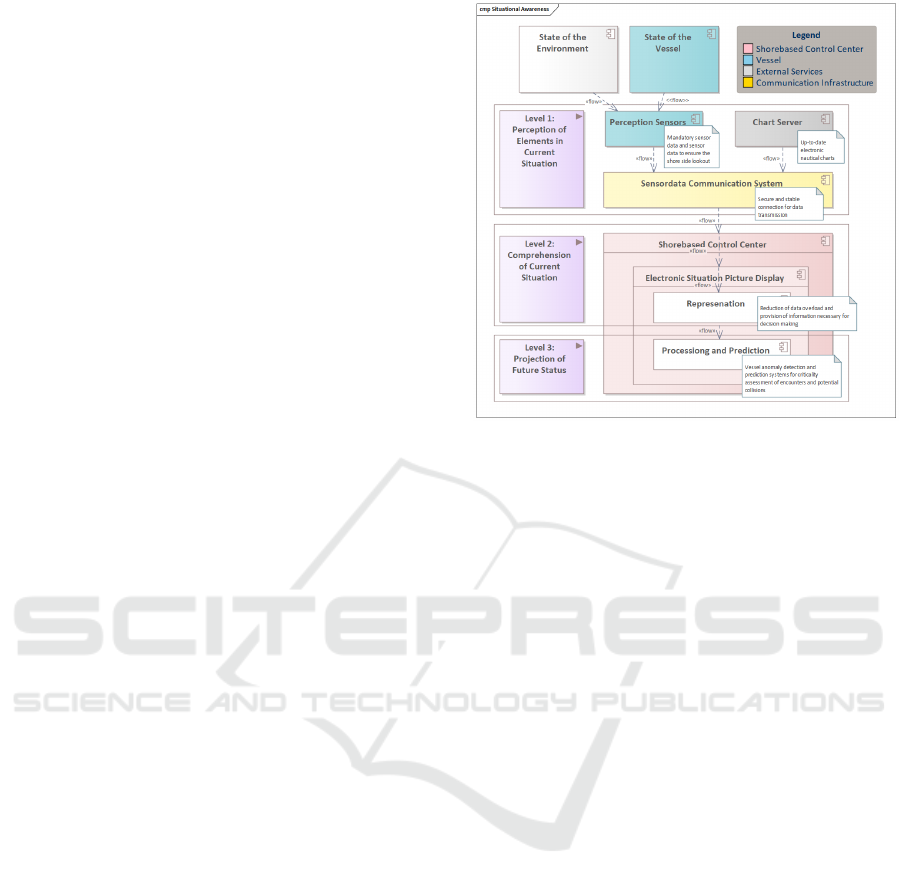
control center (Figure 1).
Accordingly, the maritime domain already offers
a broad range of technologies and sensors that are
necessary for SA and serve as the basis for the digital
representation of the different levels of SA.
Figure 1: The three levels of situation awareness with the
embedded SCC components for situation awareness.
The first level is the perception of surrounding
elements in current situation and the internal state and
condition of the vessel. Next to the existing sensor
information the selection of suitable sensor
technologies for the acquisition of relevant
information, as well as the processing and extraction
of essential attributes, is of primary importance.
During data acquisition, objective processing is
crucial to be able to represent the observations of
reality on a digital level and without loss of
information, and to enhance them with meaningful
meta-information. The goal is therefore to transmit
the (sensor) information that is normally available to
the bridge personnel on the ship in real time securely
to a remote decision-maker. Furthermore, the
question must be clarified which information about
the mentioned technologies is missing or necessary
for decision making.
In shipping, the assessment of an encounter is the
responsibility of the experts who monitor the
operation of the ship (Officer of the Watch; OOW)
and are accordingly responsible for the safety on
board, as well as the ship's command. For control
purposes, a situation assessment is made from shore,
by independent VTS, in order to contact the ships if
necessary. As these two areas of responsibility are
still clearly different from each other, a SCC cannot
be compared with a VTS center. As already
mentioned in the introduction, the SCC is responsible
for the microscopic view of a selected traffic user,
whereas a VTS center takes a macroscopic view of
the overall traffic and traffic management. It has a
regulating and controlling role.
ICINCO 2022 - 19th International Conference on Informatics in Control, Automation and Robotics
20

To standardize the procedure on the ship's bridge,
the International Chamber of Shipping (ICS) has
created the Bridge Procedure Guide (International
Chamber of Shipping (ICS), 1998). This contains
checklists and guidelines for safe action on the bridge,
including voyage planning and monitoring. The issue
of situational awareness is also addressed. According
to the Bridge Procedure Guide, situational awareness
on the ship's bridge includes "knowing where the ship
is, where it should be, and whether another ship, an
event, or conditions developing nearby pose a risk to
the safety of the ship." (International Chamber of
Shipping (ICS), 1998). In addition, the Guide
provides the following guidance on the use of
electronic aids:
- Use of lookout, ECDIS, radar, and visual
surveillance techniques to confirm the
navigational safety of the vessel and monitor
traffic
- Cross-checking information from multiple
sources.
Care should be taken to ensure that information
available on electronic navigation devices remains
clear and relevant to the current situation. Relying
purely on electronic aids is not recommended by the
guide. From these statements, however, conclusions
can be drawn for the second level of the situational
awareness framework the comprehension of the
current situation. A look-out is crucial in order to get
a picture of the current situation via unfiltered
representations. Further, a data fusion of the
underlying sensor information is crucial to avoid
sources of error and missing data.
Based on this information, the navigator evaluates
the current situation and checks for anomalies and
prospective critical conditions that need to be dealt
with and have a direct impact of the own vessel. This
process seamlessly transitions to third level, the
projection of future status. Based on this information,
the navigator can make a decision which results in an
action, usually a maneuver, i.e. a steering operation
on the vessel.
The essential technologies and their components
for efficient ship navigation as well as for the
situational awareness levels are largely listed in
Regulation 19 ("Carriage requirements for shipborne
navigational systems and equipment") of SOLAS
Chapter V (IMO, 2020). These technologies should
also be available for decision-making of the remote
operator.
The following are the essential technologies,
without redundancies, for safe and efficient
navigation, the components of which are largely
based on Regulation 19 ("Carriage requirements for
shipborne navigational systems and equipment") of
SOLAS Chapter V (IMO, 2020) based on the
requirements for all possible vessels:
Accurate positioning is necessary for navigation
on the water. Position information is provided using
a coordinate system (orthogonal grid), divided into
longitude and latitude. GNSS is a collective term for
existing or future satellite-based navigation support.
The most common implementation of these services
is the U.S. proprietary Global Positioning System
(GPS) project. To increase the accuracy of
positioning, the differential global positioning system
(DGPS) method can further help. A reference station
(fixed GNSS antenna), whose position has been
accurately determined beforehand, calculates the
error of the orbit and time system and sends
correction data to the available receivers (IMO,
2015). The position navigation and timing (PNT)
system must be designed to be resilient to interference
for the safety of the ship. For this purpose, position
data from various sources are checked and merged
into secured information. In addition to the satellites,
motion data which might be given out by an inertial
measurement units (IMUs) are synchronized with the
satellite signals to compensate disconnections or
interference (IMO, 2017).
In addition to the ship's position, the ship's course
is also crucial for navigation. The two tools approved
for determining the north direction in SOLAS are the
magnetic compass and the gyro compass. By means
of the direction of movement (compass) and speed
(log), the ship's command can also perform the
approximate location determination without direct
measurement (dead reckoning). Furthermore, the
heading needs to be provided as well as the rate of
turn (ROT), which indicates how the ship is aligned
and shows the speed perpendicular to the vessels
direction of travel.
On the ship's bridge, all information necessary for
safe navigation will be provided. Assistance systems
will complement existing systems to relieve
personnel and increase safety and efficiency of ship
operations. Nautical charts are essential for safe
navigation in (unknown) sea areas. Important
information such as water depth, coast lines or
buoyage, which nautical personnel need for route
planning, is recorded in the nautical chart and is
constantly updated. Electronic Navigational Charts
(ENC) have become established in commercial
shipping. These ENCs are available in the IHO-S-57
standard and can be displayed using an Electronic
Chart Display and Information System (ECDIS). For
the exchange and standardization of hydrographic
data, the S-100 standard version 1.0 was published in
Shore based Control Center Architecture for Teleoperation of Highly Automated Inland Waterway Vessels in Urban Environments
21

2010. From this product family, for example, the S-
101 standard will replace the S-57 in the long term.
S-100 is a framework document intended for the
development of digital products and services for
hydrographic, maritime, and GIS (geographic
information systems) communities.
Probably the most established technical tool for
collision avoidance on the bridge is the radar system,
which today is predominantly used in combination
with a radar image evaluation device (Automatic
Radar Plotting Aid; ARPA). In addition to manual
and automatic target detection and tracking, ARPA
also determines the course and speed (target
movement) of other traffic users. Based on this,
Closest Point of Approach (CPA), Time to Closest
Point of Approach (TCPA), and Distance at/to
Closest Point of Approach (DCPA) are determined
and warnings are issued if necessary (IMO, 1995).
Since 2000, AIS has been firmly anchored in
SOLAS as an additional system for protection against
collisions. Radar data are enriched by electronically
exchanged information. AIS is a ship-based radio
system that allows ships to exchange detailed
information with each other (ship-to-ship).
Communication to VTS (ship-to-shore) is also
possible.
All information occurring on the ship's bridge
must be bundled and displayed in addition to the
ENC. By combining the various input devices AIS,
charts, radar, echo sounding device and log, the
system can process the available information in
advance and, if necessary, communicate acoustic and
visual alarms to the bridge personnel (automatic
voyage monitoring). The functions of an ECDIS
system range from general chart management and
various planning functions to voyage monitoring.
GMDSS refers to all technical facilities, services
and rules for worldwide assistance in emergencies
and for securing navigation. This includes the marine
radio and NAVTEX (Navigational Text Messages),
as well as emergency transponders, satellite systems
with ground stations and worldwide emergency
response centers (Maritime Rescue Coordination
Centers; MRCC). Safety information and immediate
weather warnings (high winds, storms or hurricanes)
are communicated via NAVTEX to all ships within a
radius of approximately 400 nautical miles. In
addition to weather warnings, navigation warnings
and SAR information are also transmitted via this
information system.
Additional to maintain completeness, the ship
should be equipped with a daylight signal lamp, a
telephone, a bridge navigational watch alarm system
and a heading or track control system.
In addition to the sensors, which are used for
monitoring the environment of the vessel as well as
the navigational situation picture there are several
sensors which monitor the internal state and condition
of the vessel. In general, they monitor the whole
propulsion system, including the engine, rudder,
thruster and other operational related systems of the
vessel. Regarding the complexity of the engine itself
and the existing engine monitoring of vessels in the
commercial shipping, the representation and scope of
the monitoring of the engine need to be determined
for each vessel independently. Same applies for the
rest of the propulsion system, like the rudder and the
thrusters. The complexity of the monitoring is
influenced by the size of the vessel as well as the
types of the propulsion parts. While the propulsion
monitoring of a small research vessel could be simple
the complexity of monitoring the propulsion of a
container ship cannot be compared to the small
research vessel. So further the propulsion as well as
its monitoring is seen as black box, whose complexity
differs from ship to ship.
3.2 The Remote-control Perspective
In order to move the control of highly automated and
autonomous vehicles to the shore side, not only ship
to shore communication needs to be discussed and
clarified, but especially shore to ship communication.
To propagate possible commands to the ship, a
unified and standardized interface must be designed
that can be addressed by different entities to take
control of remote-controlled vessels at any time and
any place. Since the motorization in shipping is
characterized by a high degree of heterogeneity, the
interface for controlling ships must be completely
rethought and the response of the steering system
must be interpreted directly on the ship and monitored
by the remote operator. According to the MUNIN
project results (Fraunhofer CML, 2016), one operator
can be used for up to six different vessels, if the
operator just instructs and monitors the autonomous
system. As a consequence, the operator needs a
uniform control interface that works independently of
the vessel characteristics, this is also the case in the
situation room. The situation room is a specific room
which can be used to steer the vessel directly inside
the approach of the MUNIN project. This means that
for example, instead of the rudder angle, the change
in the ship's course or heading is controlled as a
steering command and the translation to the ship must
be made internally. But further the SCC should
include the ability to work on each level of remote
control to allow the remote operator instructing the
ICINCO 2022 - 19th International Conference on Informatics in Control, Automation and Robotics
22

system (if exists) which provide the autonomous
functionality or to directly steer the ship. External
intervention within a safety-critical system requires
that the communication and the ship can be reliably
controlled. The challenge is, on the one hand, to
secure the authentication between the ship to be
remotely controlled and the control center and, on the
other hand, to make the communication reliable.
Furthermore, if the communication is not reliable as
expected, the remote-controlled vessel needs
procedures to handle communication interruptions or
disconnections. Accordingly, to the Bridge Procedure
Guide the remote operator like the OOW should ensure
compliance with the COLREGs and should not hesitate
to use the different propulsion parts as well as other
signalling apparatus to ensure this compliance
(International Chamber of Shipping (ICS), 1998).
Based on these requirements the one-way transmission
time is a special key factor of the remote control, and
in an extended understandings also the round-trip time.
Regarding the one-way transmission time from the
International Telecommunication Union (ITU), which
was defined as 400 ms for the upper limit
(Telecommunication Standardization Sector of ITU,
2003), sending control commands should not take
longer to ensure the fast execution of transmitted
commands. Further to ensure the remote operator gets
feedback from the remote-control system the round-
trip time of the message should not exceeded 800 ms.
4 CONCEPT FOR A SHORE
BASED CONTROL CENTER
The previous chapters have provided the basis for the
following concept. The insights from the related work
and also the derived challenges clearly show that for a
shore based control system three subsystems are
essential: The ship, the communication infrastructure,
and the control center. Since the control and decision
center are decoupled from the vehicle, it is mandatory
that the system to be controlled (ship) can provide all
necessary information by itself and can also process
and execute the necessary commands. In the following,
the required functions of the individual subsystems of
the overall system architecture will first be explained
and described in more detail. Finally, the overall
architecture is presented (cf. Figure 2).
4.1 Communication Infrastructure
The basis for the reliable remote-control capability is
the communication link between the ship and the
SCC. This communication link is provided using a
centralized communication infrastructure (CCI). This
CCI has several advantages, while the most important
is that through the centralization of the
communications infrastructure, ships can be
controlled from multiple SCCs and, conversely, the
SCC should be able to remotely control multiple
vessels. A distribution also has different advantages
like avoiding a single point of failure in this
infrastructure, when one SCC crashes. Moreover, the
CCI allows several SCCs to monitor and control more
than one ship at the same time. The CCI links the
vessels with the SCCs and allows the communication
of control commands as well as transfer data, which
can be monitored. In addition to the system which
provides the distribution of messages, the CCI should
include a sensor observation service (SOS). The
Sensor Observation Service (SOS) is a service for
querying real-time sensor data. The offered sensor
data includes descriptions of sensors
themselves (using SensorML as Modelling
Language), as well as the measured values, (in
Observations&Measurements (O&M) format). All
three solutions are concepts of the Sensor Web
Enablement Framework (SWE) defined by the Open
Geospatial Consortium (OGC). The SOS can also be
implemented transactionally (SOS-T), so that new
sensors can be registered via the service interface and
subsequently measured values can be inserted. This
service should enable the SCC to filter and adjust
received sensor data for a specific use case or task,
while all other SCC are not affected by this
configuration.
4.2 Vessel
The second system to be described is the vessel,
which should be remotely controlled. The vessel
needs to contain components, which fulfill the
requirements to assure the situational picture creation
and decision making as well as the remote-control.
The vessel first needs to provide each relevant data
for the situation awareness. This data should contain
the measurements from the navigational, perception,
and internal state sensors, in short, each data which can
be measured on the vessel itself and can be used to get
the situation awareness. This collection should include
each relevant sensor on the vessel, like described in the
situational awareness section.
The vessel needs to accept incoming messages
and further process them into actuation, depending on
the available and provided remote-control level. For
this purpose, as a basis the vessel needs to be able to
control the propulsion, the engine as well as other
Shore based Control Center Architecture for Teleoperation of Highly Automated Inland Waterway Vessels in Urban Environments
23
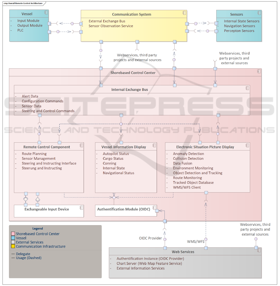
actuators on ship. These additional actuation elements
can be for example the trim control to adjust the
stability of the vessel. The actuation components can
be steered with programmable logic controllers
(PLC) which are used as an interface between the
actuation elements and the system which process the
control commands. The system which processes
incoming commands, in the architecture called input
module, can represent a system with a concrete logic
or intelligence that makes decisions and decomposes
the commands to the control level and performs a
comparison between in- and output, or it can pass the
control commands directly to the actuation instance.
So, it could be an autonomous function, which
navigates and controls the ship fully autonomous, as
well as an interface, which just forwards incoming
commands to the specific PLCs.
4.3 Shore based Control Center
The architecture of the SCC can be divided into four
main components, which ensure the functionality of
the SCC. These components are the internal exchange
Figure 2: Overall architecture of the shorebased control center and the interfaces, connections and functions between ship and
shore.
ICINCO 2022 - 19th International Conference on Informatics in Control, Automation and Robotics
24

bus, the remote-control component, the vessel
information display (VID) and the electronic situation
picture display (ESPD). The internal exchange bus
provides a communication infrastructure within the
SCC. This allows the different components to interact
with each other. Further the remote-control
component provides the necessary functionalities to
steer a vessel and planning the journey. The VID and
ESPD provide together the situational picture, where
the remote operator can observe the navigational,
perceptional, and internal situation and state of the
vessel. All components should use the same
authentication module (e.g., OpenID Connect), to
ensure authentication within the whole infrastructure.
The authentication can be provided by external
services and should not be further regarded.
The internal exchange bus (IEB) provides the
inter process communication for the SCC. The IEB is
used by the several components inside the SCC to
communicate with each other as well as the interface
between the CCI and the remote-control center.
Messages are forwarded from the remote-control
component to the CCI and data from the CCI is
distributed to the existing components inside the
SCC. Further the actions inside the SCC could be
monitored and analyzed.
The second component addresses the remote-
control. It must provide a steering and instructing
interface, which should be able to process inputs of
the remote operator. Further the remote-control
component uses an interface for external input
devices, to have the ability to connect different input
devices to the remote control and also to integrate and
expand new steering devices. External input devices
can be any kind of physical or virtual controllers, like
joysticks, azimuth levers, ship consoles or touchpads,
while the external input device component provides
the interface between the physical and virtual layer.
The steering and instruction interface forward the
instructions or steering commands into the main
logic, which is provided by the steering and
instruction component. The component processes the
given inputs and forward them using the IEB. By
decoupling the control component from the
processing component, it is possible to take over
control at different levels. For example, at the
strategic planning level, routes can be specified for
the vehicle to follow. At a lower level, it is possible
to define maneuvers to be performed by the vehicle,
for example to avoid an obstacle or to change or
adjust the heading by a defined degree. Alternatively,
at the controller level, it is possible to actuate the
rudder or engine systems directly.
The second part of the remote-control component
is the sensor management. The SCC must be able to
manage the sensors, from which they get information.
At least the steering and instructing interface need to
provide the strategic planning, like the route planning.
The route planning provides the functionality to
create routes, which can be send as strategic
command to a remote-controlled vessel. For the
consistent route planning nautical data is need, which
leads to the second main component of the SCC, the
Electronic Situation Picture Display (ESPD).
As mentioned, the situational picture is provided
by two components, the ESPD and the VID. The
ESPD provides a visualization and the same
functionalities as an ECDIS on the ship. The used
ENC can be accessed via an external web map
services (WMS), there additional information can be
retrieved using web feature services (WFS). Using
ENC from external services allows the remote
operator to access the latest information, warnings, or
rules. Additionally, the planning from the remote-
control component can be performed using the
available data. Further the ESPD can be used for
anomaly and collision detection after the data from
the IEB is processed. This processing is necessary to
improve the quality of the measurements through
sensor fusion and use a database to store the tracked
objects afterwards. These objects can be used for
further analysis or for prediction and planning
purposes. The ESPD can be extended to several other
services which can use the data to support the remote
operator by controlling the vessel and during the
decisions making process. Also, the monitoring of the
environment must be provided by the ESPD. The
information could be provided by the vessel but in
addition other information sources could be used, as
already mentioned with ENC data. For further
measurements different sources can be used and
integrated into the architecture.
The Vessel Information Display (VID) visualizes
the state information from the vessel, which includes
the several measurements. It should provide all
information which were described in the situational
awareness chapter. Further the navigational as well as
the autopilot status can be displayed. The monitoring
of cargo is also considered here.
5 EVALUATION
The overall architecture developed is evaluated in
several steps. First, the technical feasibility is
demonstrated, and the implemented setup is briefly
shown. Second, the delay measurements are
Shore based Control Center Architecture for Teleoperation of Highly Automated Inland Waterway Vessels in Urban Environments
25

evaluated. While the MUNIN project already
evaluates the applicability of streaming sensor data
using the different communication technologies, the
evaluation only considers the control commands.
Finally, the SCC is evaluated against the function of
an INS. The evaluation took place in the maritime
testbed environment eMIR in the context of the
AVATAR research project. The AVATAR research
project is about reactivating strategically useful
waterways to relieve road traffic as a transport route.
In order to make waterways visible as a more
attractive alternative, it is necessary to increase the
degree of autonomy for this mode of transport. To
demonstrate the feasibility of autonomous inland
waterway vessels, the practical feasibility of the
various automation levels will be demonstrated. Since
the first step towards an autonomous waterborne
vessel is teleoperation, and that the remote-control is
reliably carried out over land. The used maritime
testbed environment eMIR consists of a physical and
a virtual testbed (Rüssmeier et al., 2019). The
physical testbed contains the research platforms that
was used for testing the systems under test.
Furthermore, the physical test field also includes the
reference waterway, which enables monitoring of the
research platforms during tests.
5.1 Setup for Implementation and
Testing
To implement the architecture shown, RabbitMQ
4
is
used as the basic communication infrastructure.
RabbitMQ is a message broker that can provide
configurable queues to forward messages to the
connected consumers. Here it is possible to create
multiple queues for the sensor data as well as remote-
control commands. Since it is necessary to keep the
bandwidth and the data volume as low as possible, the
messages can be serialized with the help of Protocol
Buffers
5
. In addition, Remote Procedure Calls (RPC)
can be used, so that it can be ensured that the
commands were received by the client, and the
remote operator receives feedback. For the collection
of sensor data, sensors can be used, which in turn can
be connected in an NMEA2000 network, for
example. NMEA2000 is a bus based on the CAN
protocol and can be used to connect devices to the
vessels network. From this network, the
measurements can be retrieved and read out using
libraries such as CANBoat
6
, which can be wrapped,
4
https://www.rabbitmq.com/
5
https://github.com/protocolbuffers/protobuf
6
https://github.com/canboat/canboat
and the received messages can be published on the
RabbitMQ exchange bus. The IPC of the SCC can be
implemented by another RabbitMQ server, both
RabbitMQ servers can then be connected to each
other using a shoveling approach. In this case, the
messages from individual queues are forwarded to the
queues of the other server. The authentication can be
implemented using OpenID Connect, which can be
provided by a Keycloak
7
instance. With the help of
Keycloak, identity and access management can be
performed. An alternative could be the use of the
Maritime Connectivity Platform
8
(MCP), which
would provide a token in the same way as Keycloak.
The components within the SCC were implemented
using Java and JavaFX
9
for the frontend.
As remotely controlled vehicle a small research
boat was used. This has the sensor technology
required for the evaluation. The flexible, sustainable
architecture of the research boat enables the
integration and expansion of the functions required
for the evaluation, such as the measurement of the
round-trip time (RTT) timestamp. In addition, the
experimental vehicle provides the possibility of
processing incoming control commands using RPC
over RabbitMQ that can be processed and interpreted
directly by the motor and control unit. The control
interface of the research boat was developed to realize
the teleoperation of inland ships and formations
(platooning). The connection from the research boat
was provided via mobile network (4G), while the
implementation was focused on coastal areas as well
as inland areas, where the coverage of 4G meets the
requirements. The implemented VID was able to
display all relevant data from the vessel. While the
size of the used vessel was small, also the number of
installed sensors were limited and manageable. The
ESPD within the SCC was able to display the map
from an external web map service and to show all
detected objects. Further with the remote-control
component it was possible to directly control the ship
by setting the rudder angle and the relative thrust.
5.2 Applicability Evaluation of the
Remote-control
Like described in the remote-control chapter, the
overall one-way transmission time of the remote
control should not exceed 400ms, while the RTT,
should not exceed 800ms considering the one-way
transmission time. Several different field tests were
7
https://github.com/keycloak/keycloak
8
https://maritimeconnectivity.net/
9
https://github.com/openjdk/jfx
ICINCO 2022 - 19th International Conference on Informatics in Control, Automation and Robotics
26

made in a coastal area. The one-way transmission
time as well as the RTT was measured performing
different maneuver tasks, like turning, evading and
driving forward with course adjustments. Further the
measurements were performed on several days with
different climate conditions. In total 1475 command
executions were made, where 584 executions were
engine commands and 891 were rudder commands.
The size and length of the commands was the same.
The allocation between the one-way transmission
time from and to the vessel is nearly in all executed
commands the same, so it is not further regarded. The
allocation of the RTT can be seen in Figure 3.
Figure 3: Deviation of control command RTT of different
field tests, evaluating 1475 command executions.
The Figure 3 shows that the most command RTT
is below 500 ms, which match the requirements of
800 ms for the RTT. Further about 10 percent of the
engine as well as the rudder commands are outliers,
where a part can be seen as measurement deviations.
The RTT of the most command was approx. 105 –
260 ms, which is much lower than the requirement
value.
5.3 Comparison with INS
As mentioned earlier, an SCC should include the
functionalities and components that are specified by
INS so that the essential properties are also available
on the shore side. The work of Lund et al. (2018) , has
summarized the core components of common INS
solutions from various works. The essential seven
parts are compared to the SCC architecture in the
following to show the completeness of the solution.
The seven components are: existing workstations, an
overall operating system, sensor integration,
networking, radar information, an ECDIS controlled
autopilot and a stable internet connection. The first
component, workstation, comprises the hardware,
which must be seen in connection with the operating
system, which is also the second component. In order
to mitigate the point of the operation system, it is
recommended to use operating system-independent
solutions when selecting the software solutions to be
used. That results in the fact, that for the SCC it is not
required to have a specific operating system allowing
safety and time-critical processes to run on real-time
capable systems. Visualization solutions of the SCC
can run on less critical systems. In a broader sense,
the SCC could provide a multi-function display. The
sensor integration is provided via the CCI, as well as
all other information flows such as radar or steering
commands. Steering commands including the
activation and control of the autopilot function as well
as autonomous systems. Accordingly, the
components of the sensor integration, the radar and
the ECDIS controlled autopilot are also provided. For
the SCC concept a stable internet connection is
essential. The connectivity to the internet in the SCC
architecture is also considered as well. The seventh
and last component addresses the on-board network
connection. In the context of the SCC, this takes place
on the ship's side and is therefore not considered in
the SCC. The connection of the various components
on the SCC side is regulated by the internal exchange
bus, which can be based on an Ethernet network.
Accordingly, it can be seen that the SCC contains all
the required components of an INS insofar as they are
located in the SCC according to the concept. In
summary, it can be said that the SCC fulfills the
requirements as a remote INS.
6 CONCLUSION
In the paper, an architecture focusing on the
technologies and functions for the realization of a
shore-based control center was presented. It was
defined based on the requirements derived from the
regulations and the decision-making processes on the
ship's bridge. In order to support the decision-making
process, special attention was paid to the levels of
situational awareness to ensure the provision of
information at all levels. It was found that essential
information could be prepared and accessed in a
location-independent manner to support the ship's
command and control, which is an essential necessity
when decoupling the control center from the ship. It
turned out that the existing communication
infrastructure is already sufficient to realize a shore-
based control center. Only the reliability of the
transmission or more concrete the guaranteed
transmission and communication between ship-to-
shore and vice versa, as well as the resulting concepts
Shore based Control Center Architecture for Teleoperation of Highly Automated Inland Waterway Vessels in Urban Environments
27

for the fallback level are crucial for the realization. In
order to validate the completeness of the functional
scope, a comparison with the INS was aimed to
ensure that the design specifications can also be
applied to an SCC. Accordingly, further work
consists of testing the edge cases in remote control
with meaningful scenarios and creating and
presenting further technical framework conditions for
the reduction of automation risks associated with
operation phase.
ACKNOWLEDGEMENTS
The research presented in this paper is funded by the
European Union and the European Regional
Development Fund, as part of the Interreg
North Sea Region project AVATAR
(https://northsearegion.eu/avatar/).
REFERENCES
Bedny, G., & Meister, D. (1999). Theory of Activity and
Situation Awareness. International Journal of Cognitive
Ergonomics, 3(1), 63–72. https://doi.org/10.1207/s153
27566ijce0301_5
Dittmann, K., Hansen, P. N., Papageorgiou, D., Jensen, S.,
Lützen, M., & Blanke, M. (2021). Autonomous Surface
Vessel with Remote Human on the Loop: System Design
for STCW Compliance. IFAC-PapersOnLine, 54(16),
224–231. https://doi.org/10.1016/j.ifacol.20 21.10.097
Endsley, M. R. (1988). Design and Evaluation for Situation
Awareness Enhancement. Proceedings of the Human
Factors Society Annual Meeting, 32(2), 97–101.
https://doi.org/10.1177/154193128803200221
Endsley, M. R., & Smolensky, M. W. (1998). Situation
awareness in air traffic control: The picture. In Human
factors in air traffic control. (S. 115–154). Academic
Press.
Fraunhofer CML. (2016). Research in maritime autonomous
systems project Results and technology potentials.
Guo, W., Wang, S., & Dun, W. (2015). The Design of a
Control System for an Unmanned Surface Vehicle. The
Open Automation and Control Systems Journal, 7(1),
150–156. https://doi.org/10.2174/18744443015070101
50
IEC. (2007). Maritime navigation and radiocommunication
equipment and systems – Integrated navigation systems
– Part 2: Modular structure for INS – Operational and
performance requirements, methods of testing and
required test results.
IMO. (1995). Performance Standards for Automatic Radar
Plotting Aids (ARPAs)—A.823(19).
IMO. (2007). Adoption of the Revised Performance
Standards for Integrated Navigation Systems (INS)—
MSC 83/28/Add.3.
IMO. (2015). Performance Standards for Multi-System
shipborne Radionavigation Receivers—MSC
401(95)/22/Add.2.
IMO. (2017). Guidelines For Shipborne Position, Navigation
And Timing (Pnt)Data Processing—MSC.1/Circ.1575.
IMO. (2018). E-Navigation Srategy Implementation Plan –
Update 1. IMO.
IMO (2020). SOLAS: Consolidated Edition 2020
(Consolidated edition 2020, seventh edition).
International Chamber of Shipping (ICS). (1998). Bridge
Procedure Guide, 3rd ed.
Lund, M. S., Gulland, J. E., Hareide, O. S., Jøsok, . &
Weum, K. O. C. (2018). Integrity of Integrated
Navigation Systems. 2018 IEEE Conference on
Communications and Network Security (CNS), 1–5.
https://doi.org/10.1109/CNS.2018.8433151
MacKinnon, S. N., Man, Y., & Baldauf, M. (2015). D8.8:
Final Report: Shore Control Centre. http://www.unman
ned-ship.org/munin/wp-content/uploads/2015/09/MUNI
N-D8-8-Final-Report-Shore-Control-Centre-CTH-final.
pdf
Porathe, T. (2014). Remote Monitoring and Control of
Unmanned Vessels –The MUNIN Shore Control Centre.
8.
Porathe, T., Prison, J., & Man, Y. (2014). Situation
Awareness in Remote Control Centres for Unmanned
Ships. Human Factors in Ship Design & Operation, 105–
114. https://doi.org/10.3940/rina.hf.2014.12
Rüssmeier, N., Lamm, A., & Hahn, A. (2019). A generic
testbed for simulation and physical-based testing of
maritime cyber-physical system of systems. Journal of
Physics: Conference Series, 1357(1), 012025.
https://doi.org/10.1088/1742-6596/1357/1/012025
Smith, K., & Hancock, P. A. (1995). Situation Awareness Is
Adaptive, Externally Directed Consciousness. Human
Factors: The Journal of the Human Factors and
Ergonomics Society, 37(1), 137–148.
https://doi.org/10.1518/001872095779049444
Son, N. S., Kim, S. Y., & Van, S. H. (2004). Design of an
operation control and remote monitoring system of small
unmanned ship for close-range observations. Oceans ’04
MTS/IEEE Techno-Ocean ’04 (IEEE Cat.
No.04CH37600), 2, 1093–1101. https://doi.org/10.11
09/OCEANS.2004.1405663
Stateczny, A., & Burdziakowski, P. (2019). Universal
Autonomous Control and Management System for
Multipurpose Unmanned Surface Vessel. Polish
Maritime Research, 26(1), 30–39. https://doi.org/
10.2478/pomr-2019-0004
Telecommunication Standardization Sector of ITU. (2003).
International telephone connections and circuits –
General Recommendations on the transmission quality
for an entire international telephone connection—One-
way transmission time (G.114; Series G: Transmission
Systems And Media, Digital Systems And Networks).
https://www.itu.int/rec/T-REC-G.114-200305-I/en
Zhang, H., & Zhang, Z. (2021). Design of the Power System
and Remote Control System for the Unmanned Ship.
Journal of Physics: Conference Series, 2121(1), 012021.
https://doi.org/10.1088/1742-6596/2121/1/01 2021
ICINCO 2022 - 19th International Conference on Informatics in Control, Automation and Robotics
28
