
Design and Modeling of a Numerical Simulator of a
Mini-hydropower for Performance Characterization of the
Turbine Type of Francis, Cross-flow and Pelton
Francis Kifumbi
1
, Guyh Dituba Ngoma
1
, Python Kabeya
2
and Clement N'zau Umba-di-Mbudi
3
1
University of Quebec in Abitibi-Témiscamingue, School of Engineering, Rouyn-Noranda, Canada
2
University of Kinshasa, Faculty of Polytechnic, Kinshasa, Democratic Republic of the Congo
3
University of Kinshasa, Faculty of Science, Kinshasa, Democratic Republic of the Congo
Keywords: Hydraulic Turbine, Blades, Buckets, Draft Tube, Cavitation, ANSYS-CFX, Computational Fluid Dynamic
(CFD).
Abstract: This research work deals with the design of a numerical simulator which consists of an upstream reservoir, a
penstock, a Francis turbine, a cross-flow turbine, a Pelton turbine, and a draft tube. This simulator can allow
to better study the performance of a mini-hydroelectric plant while investigating the parameters involved
with the cavitation phenomenon for the Francis turbine. From existing reference data of the gross head, the
flow rate and the rotating speed for the Francis turbine, the cross-flow turbine and the Pelton turbine, the
geometrical parameters of the turbine runners were calculated using inter alia the specific speeds, the
turbines diagrams and the empirical equations. Moreover, the equations of continuity and Navier-Stokes are
applied to obtain by means of the ANSYS-code the fields of the liquid flow velocity and the pressure. The
numerical results achieved for the turbine output power and the efficiency were compared with the
experimental results from the existing test benches of turbines in the turbomachinery facility of the
Engineering School at the University of Quebec in Abitibi-Témiscamingue (UQAT). Also, the effect of the
cavitation on the efficiency of the Francis turbine account for the draft tube height is analyzed. The impact
of the draft tube height of the Francis turbine and the jet width of the cross-flow turbine on the output power
and the efficiency is examined.
1 INTRODUCTION
The decentralized production of electricity from
renewable sources is evolving very significantly and
is constantly increasing day by day, reducing the
dependency on fossil fuels and the production of
greenhouse gases. The realization of the big
hydroelectric power stations having become difficult
due inter alia to the scarcity of sites and
environmental restrictions on a world scale. That
brings out the necessity to develop mini-hydropower
plants with power lower to 10 MW.
Several research works that made objects of
publication have been achieved on the morphology
of the turbine components of the mini hydroelectric
power stations. A review of low head micro-
hydropower turbines was done focusing on the
categories, the performance, the operation and the
cost (Elbatran et al., 2015). The geometrical and
structural study of the mechanical constraints that
the blades of a cross-flow turbine undergo in full
charge was done (Zanette, 2010). It was found that
the mechanical stress sustained by the blades
depends on the basic geometrical specifications of
the cross-flow turbine, the rotating speed, the exact
geometry of the blades and the velocity of the
upstream water current. In addition, the author
(Bartle, 2002) presented the current role that
hydropower is playing in the world, along with some
its inherent benefits, and then looks at the remaining
potential, and some specific development plans in
various regions of the world. Attention was drawn to
the advantages of developing hydropower as part of
a multipurpose water resources scheme, often
enabling it to subsidize other valuable functions of a
reservoir or river system. In the article (Olgun,
2000), it was investigated the effects of shape of
guidance tubes to the interior of the cross-flow
turbine and they achieved another parametric study
226
Kifumbi, F., Ngoma, G., Kabeya, P. and Umba-di-Mbudi, C.
Design and Modeling of a Numerical Simulator of a Mini-hydropower for Performance Characterization of the Turbine Type of Francis, Cross-flow and Pelton.
DOI: 10.5220/0011265000003274
In Proceedings of the 12th International Conference on Simulation and Modeling Methodologies, Technologies and Applications (SIMULTECH 2022), pages 226-233
ISBN: 978-989-758-578-4; ISSN: 2184-2841
Copyright
c
2022 by SCITEPRESS – Science and Technology Publications, Lda. All rights reserved

on the influence of the nozzle width according to the
width of the runner and the blade number (Olgun,
1998).
Moreover, the study of Pelton turbines was
deeply developed (Zhang, 2016) inter alia in terms
of the injector characteristics, the interaction
between the jet and Pelton runner, the hydraulic
design of Pelton turbines, and the bucket mechanical
strength and similarity laws. In the article (Panthee
et al, 2014), the CFD analysis of scaled Pelton
turbine Hydropower was performed using ANSYS
CFX software to determine the torque generated by
the turbine and the pressure distributions in the
bucket. It was found that the torque results obtained
from the single bucket can be replicated over time to
predict the total torque transferred by the Pelton
turbine. The study of (Židonis et al., 2015) was
based on the influence of the bucket number of a
Pelton turbine for the mini-hydropower plant, the
interaction of the water jet on the runner in rotation
and finally to make a comparison between the
numerical results of the Ansys-CFX and ANSYS-
Fluent codes. Furthermore, in the article (Kaewnai et
al., 2011), the study to improve the runner design of
Francis turbine and analyze its performance using
Computational Fluid Dynamics was accomplished.
In the article (Alligne et al., 2014), it was
investigated the cavitation surge modelling in
Francis turbine draft tube. Thus, the parametric
analysis of the draft tube model was carried out to
examine the influence of turbine variables on the
cavitation surge onset identified by the hydraulic
system stability. In addition, The Francis turbine was
studied considering the speed variation (Trivedi et
al., 2020). A particular focus was given to the
inception of cavitation. The work showed specific
instances of cavitation, where the large part of the
turbine was cavitating intensely, including stay vane
and guide vane passages. It was found that the
cavitation becomes intense while crossing the
threshold value of rotating speed.
Despite the described previous works, a
numerical model of hydroelectric mini-power
stations provided with the Francis turbine, cross-
flow turbine and Pelton turbine being able to serve
as a numerical test bench is not investigated.
Therefore, in this research work, it is to develop a
numerical simulator to study turbine characteristics
under different operating conditions for the turbine
type of Francis, cross-flow and Pelton. The first step
of the research is focused on the turbine runners as
presented in this paper.
2 MODEL DESCRIPTION
The model of the mini-hydropower considered in
this work is illustrated in Figure 1. It is composed,
inter alia, of an upstream reservoir, a downstream
reservoir, a penstock and one of the three types of
the turbine: Francis, Cross-flow and Pelton.
The solid models of the turbine runners are
shown in Figure 2.
Figure 1: Model of the mini-hydropower.
a) Francis b) Cross-flow c) Pelton
Figure 2: Solid models of the turbine runners.
3 MATHEMATICAL
FORMULATION
To determinate the field of the liquid flow
velocity and the field of the pressure in the
hydraulic turbines, the following assumptions are
considered for the liquid flow: (a) a steady state,
three-dimensional and turbulence flow using the
k-
ε
model is assumed; (b) the liquid is an
incompressible liquid; (c) it is a Newtonian liquid;
and (d) the liquid’s thermophysical properties are
constant with the temperature.
3.1 Equation of the Continuity
The equation of the continuity (Malonda et al.,
2021) is given by:
uvw
0
xyz
∂∂∂
++ =
∂∂∂
(1)
where u(x,y,z), v(x,y,z) and w(x,y,z) are the
components of the liquid flow velocity U(u,v,w).
Design and Modeling of a Numerical Simulator of a Mini-hydropower for Performance Characterization of the Turbine Type of Francis,
Cross-flow and Pelton
227

3.2 Equations of Navier-Stokes
The equations of the Navier-Stokes (Malonda et al.,
2021) are written as follows:
222
eff
222
2
zx z x
222
eff
222
uu u uuu
uvw
xy z
xyz
p
( r 2 v) g
x
vv v vvv
uvw
xy z
xyz
∂ ∂ ∂ ∂∂∂
ρ++ =μ ++
∂∂ ∂
∂∂∂
∂
−+
ρ
ω+ω+
ρ
∂
∂∂ ∂ ∂∂∂
ρ++ =μ ++
∂∂ ∂
∂∂∂
2
zy z y
222
eff
222
z
p
( r 2 u) g
y
ww w www
uvw
xy z
xyz
p
g
z
∂
−+ρω−ω+ρ
∂
∂ ∂ ∂ ∂∂∂
ρ++ =μ ++
∂∂ ∂
∂∂∂
∂
−+ρ
∂
(2)
where g (g
x
,g
y
,g
z
) is the gravity acceleration, p is the
pressure; ρ is the density; μ
eff
is the effective
viscosity accounting for turbulence, it is defined as
.
eff t
μμμ
=+
μ is the dynamic viscosity and μ
t
is the
turbulence viscosity. It is linked to turbulence
kinetic energy k and dissipation ε.
Equations 1 and 2 are solved by means of the
ANSYS CFX-code (ANSYS inc., 2022) to obtain
the fields of liquid flow velocity and pressure in
hydraulic turbines.
4 DESIGN PARAMETERS OF
THE HYDRAULIC TURBINES
4.1 Turbine Runners
To design the turbine runners, several parameters
must be taken in account, inter alia, the water head,
the flow rate, the rotating speed, the specific speed,
the speed triangles and the cavitation factor. The type
of the turbine runner depends on the specific speed
(Peng, 2008). Moreover, the synchronous rotating
speed of the turbine when the generator is directly
coupled with the turbine can be determined by:
1
p
N 120fn
−
=
(3)
where f is the electrical frequency and n
p
is the even
number of the generator poles.
The specific speed is the parameters that
characterize the hydraulic turbines. It is expressed
with the help of the Equations 4 and 5 according to:
a) the output power
1
2
s
s
5
4
P
NN
H
=
(4)
b) the flow rate
1
2
q
3
4
Q
NN
H
=
(5)
where P
s
is the output power, N is the rotating speed,
H is the net water head and Q is the flow rate.
Using Equation 4, the turbine type is found in
Table 1.
Table 1: Turbine type (Peng, 2008).
Turbine type
Specific speed
Ns [rpm(m
3
/s)
0,5
/m
0,75
]
Pelton
1 - 20 (with one jet)
Francis 20 - 140
In addition, the speed number is given by:
()
()
1
2
q
3
4
Q/
= 0,00633N
2gH
π
ν=ω
(6)
where ω is the angular speed.
The hydraulic power can be expressed as follows:
h
PgHQ=
ρ
(7)
The output power of the turbine is given by:
s
PT=ω
(8)
The turbine efficiency is formulated as follows:
s
h
P
P
η=
(9)
4.1.1 Francis Turbine
The Francis turbine is dimensioned accounting for
the reference data of the
existing test bench of the
Francis turbine (School of Engineering, 2022) and,
inter alia, the book (Peng, 2008). The blade number
of the Francis turbine runner is determined:
1
3
s
Z250N
−
=
(10)
Moreover, the jet flow velocity at the outlet of the
penstock can be formulated as follows:
n
v2gH=η
(11)
where η
n
is the velocity coefficient accounting of the
losses through the penstock.
The outer diameter of the Francis turbine is
determined using the method described in (Peng,
2008).
SIMULTECH 2022 - 12th International Conference on Simulation and Modeling Methodologies, Technologies and Applications
228

Concerning the cavitation phenomenon of the
Francis turbine, it takes place at the turbine
discharge, where the pressure is minimum. The
Thomas cavitation factor (Peng, 2008) is used and it
can be written by:
1.8
sp
N
0.006 0.55
100
σ= +
(12)
Furthermore, the critical cavitation factor for the
Francis turbine is formulated as follows:
2
s
c
N
0.625
380.78
σ=
(13)
Thus, to avoid the cavitation, the Thomas cavitation
factor must be more than the critical cavitation
factor.
4.1.2 Cross-flow Turbine
The dimensioning of the runner of the cross-flow
turbine is accomplished basing on the reference data
of the existing test bench (School of Engineering,
2022) and using the developed approaches in
(Birhanu et al., 2017; Desai et al., 1994; Mockmore
et al., 1949). The relevant reference data for the
cross-flow turbine are given in Table 3.
The dimensioning of the runner of the cross-flow
turbine is accomplished basing on the reference data
of the existing test bench (School of Engineering,
2022) and using the developed approaches in
(Birhanu et al., 2017; Desai et al., 1994; Mockmore
et al., 1949). The inner diameter of the turbine
runner is selected between 55 % and 66 % of the
outer diameter. In this study 66% of the outer
diameter is chosen. Figure 3 illustrates the blades
including the main parameters of the runner of the
cross-flow turbine that can be calculated using
Equations 14-20:
()
22
12 12 12
cRR2RRcos =+− β+β
(14)
()
212
Rsin
arcsin
c
β+β
ε=
(15)
()
12
ξ = 180°- β +β +ε
(16)
()( )
12
180 2
φ
=
β
+
β
−°−
ξ
(17)
()
()
1
1
Rsinf
d = = 180°-2 β +ε
2sin 180°-ξ
(18)
()
b
1
d
r
cos
=
β
+ε
(19)
22
p
b1b1 1
rrR2rRcos=+−
β
(20)
Figure 3: Runner blade (Mockmore et al., 1949).
4.1.3 Pelton Turbine
The Pelton turbine parameters are determined basing
on the reference data of the existing test bench
(School of Engineering, 2022) and the articles
(Dandekar et al., 1979; Inversin, 1981; Jeffery,
1989; Eisenring, 1991; Santolin et al., 2009; and
Zidonis, 2015). The relevant parameters of the
Pelton turbine shown in Figure 4 (Eisenring, 1991)
can be written as follows:
The absolute jet speed:
1n
c2gH=η
(21)
where η
n
is the velocity coefficient.
The jet diameter:
()
1
1
d4Qc
−
=π
(22)
The blade width:
b
2.5d à 3.2d=
(23)
The bucket height including h
1
and h
2
:
1
2
h=2.1d to 2.7d
h =0.1d to 0.35d
h =0.85d à 1.5d
(24)
The bucket depth:
t0.9d
(25)
The runner diameter:
()
1
1G
D=60u i πn
−
(26)
where i is the transmission ratio.
The rotating speed:
()
1
G1
n =60u i πD
−
(27)
The blade opening:
a = 1.2d
(28)
The allowance radium:
()
k 0.1 ... 0.17 D
(29)
The bucket number :
()
-1
z = πD 2d
(30)
The outer diameter of turbine runner:
0
D = D + 1.2h
(31)
Design and Modeling of a Numerical Simulator of a Mini-hydropower for Performance Characterization of the Turbine Type of Francis,
Cross-flow and Pelton
229
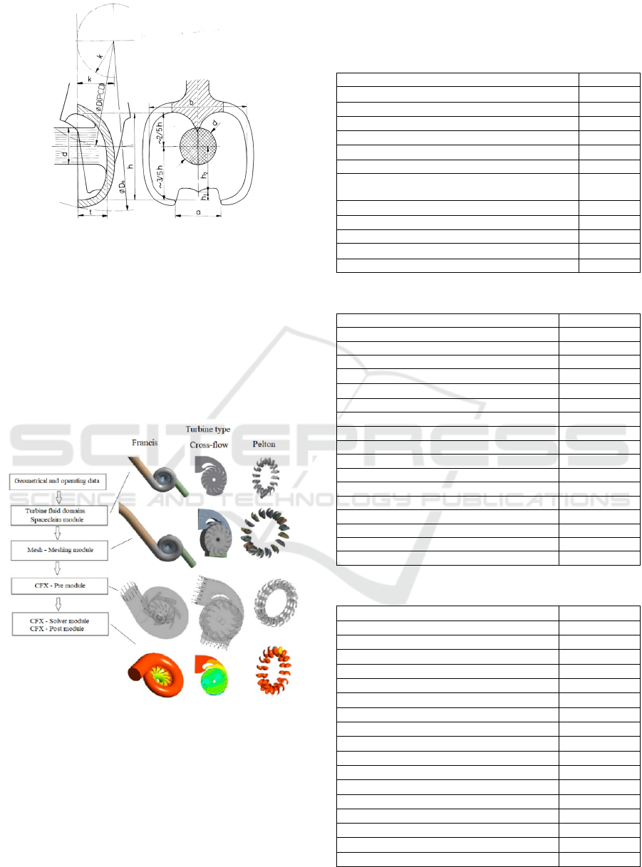
Figure 4: Bucket parameters (Eisenring, 1991).
4.2 Turbine Runner Modeling and
Simulation Steps
Figure 5 shows the modeling and the simulation
steps of the Francis turbine, the cross-flow turbine
and the Pelton Turbine using the Inventor and the
ANSYS softwares (modules: Spaceclain, CFX-Pre,
CFX-Solver and CFX-Post) and accounting for the
boundary conditions.
Figure 5: Turbine runner modeling and simulation steps.
5 RESULTS AND DISCUSSION
The numerical simulations are accomplished to
validate the developed approach, and to analyze the
effects of the draft tube length of the Francis turbine
and the jet width of the cross-flow turbine on the
output power and the efficiency. Tables 2-3 indicate
the parameter data used for the three turbine runners
after sizing.
Table 2: Parameter data for the Francis turbine.
Paramete
r
Value
Speed number 0.1344
Flow coefficien
t
0.1864
Energy coefficient 5.2095
Specific diamete
r
3.5
Outer diameter [m] 0.0819
Blade numbe
r
11
Height of the turbine center above the tail water
level [m]
8.8
Output power [kW] 0.5884
Hydraulic power [kW] 0.6194
Liquid flow velocity in the penstock [m/s] 14.6908
Specific speed in terms of the output power 76.0666
Specific speed in terms of the flow rate 21.2279
Table 3: Parameter data of the cross-flow turbine.
Paramete
r
Value
Outlet blade angle [º] 50
Inner diameter [m] 0.11088
Jet thickness [m] 0.009
Runner width [m] 0.06
Blade width [m] 0.01
Blade numbe
r
14
Injector width [m] 0.04
Blade arc radius r
b
[m]: Figure 3 0.027384
Radius
r
p
[m]: Figure 3 0.0618
Jet velocity [m/s] 14.0071
c [m] (Equation 14 ) 0.1154
ε [º] (Equation 15) 26.8385
ξ [º] (Equation 16) 43.1615
φ [º] (Equation 17) 16.3229
d [m] (Equation 18) 0.0173
r
b
[m] (Equation 19 ) 0.0188
r
p
[m] (Equation 20 ) 0.0667
Table 4: Parameter data of the Pelton turbine.
Parameter Value
Jet flow velocity
[m/s] 16.242
Nozzle coefficient 0.96 – 0.98
Jet diameter [m] 0.0229
Jet circumferential velocity
[m/s] 8.1210
Circumferential velocity coefficient 0.45 - 0.49
Bucket width [m] 0.0572
Bucket height [m] 0.0492
Lower height
[m] 0.0046
Upper height
[m] 0.0205
Bucket number 16
Transmission ratio 0.85
Bucket depth [m] 0.0206
Tangent diameter [m] 0.2198
Bucket opening [m] 0.0274
Allowance radius [m] 0.0264
Approximate bucket number 15.0938
Runner outer diameter [m] 0.2788
SIMULTECH 2022 - 12th International Conference on Simulation and Modeling Methodologies, Technologies and Applications
230
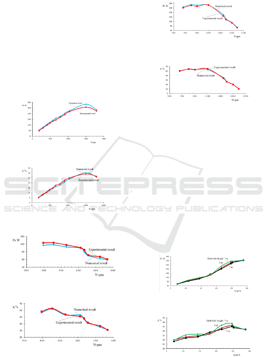
5.1 Validation of the Developed
Approach
The developed approach is validated using the
expérimental resultats from the existing test benches
for the Francis turbine, the cross-flow turbine and
the Pelton turbine (Engineering School, 2022).
Figures 6-11 illustrate the result comparison for the
three turbines between the numerical results
obtained and the experimental results for the output
power and the efficiency as a function of the rotating
speed. From these figures, a good agreement is
found between the numerical and experimental
curves.
Figure 6: Output power of the Francis turbine versus
rotating speed.
Figure 7: Efficiency of Francis turbine versus flow turbine
versus rotating speed.
Figure 8: Output power of the cross-flow turbine versus
rotating speed.
Figure 9: Efficiency of the cross-flow turbine versus
rotating speed.
Figure 10: Output power of the Pelton turbine versus
rotating speed.
Figure 11: Efficiency of the Pelton turbine versus rotating
speed.
Furthermore, the gaps achieved between both results
can be explained by the fact that the numerical
simulations don't take in account, inter alia, the
mechanical and volumetric losses.
5.2 Effect of the Draft Tube Height of
the Francis Turbine
To examine the impact of the draft tube height on
the output power and the efficiency of the Francis
turbine, the values of the draft tube height of 5 m, 6
m and 7 m are selected. Figures 12 and 13 show that
the turbine output power and the efficiency vary
little with increasing draft tube height. The increase
of the height draft tube modifies the pressure
difference between the inlet and the outlet of the
turbine runner. This leads to rise flow velocity at the
turbine runner outlet.
Figure 12: Output power of the Francis turbine versus
flow rate.
Figure 13: Efficiency of the Francis turbine versus flow
rate.
Design and Modeling of a Numerical Simulator of a Mini-hydropower for Performance Characterization of the Turbine Type of Francis,
Cross-flow and Pelton
231
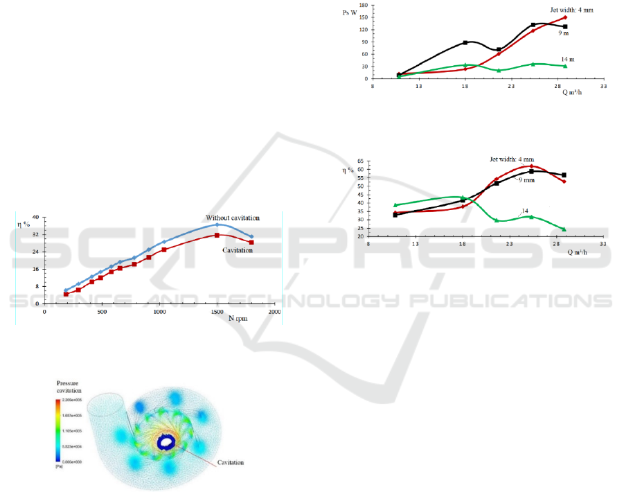
5.3 Effect of the Cavitation on the
Efficiency
To analyze the effect of the cavitation on the
efficiency of the Francis turbine, the draft tube
heights of the Francis turbine of 8.8 m without
cavitation and 9.6 m with cavitation are chosen.
Figure 14 illustrates the turbine efficiency curves as
a function of the rotating speed. It is observed that
the appearance of cavitation in the liquid flow in the
turbine runner leads to the sensitive reduction of the
efficiency. At the best efficiency point (B.E.P.)
corresponding to 1500 rpm the relative gap is 14 %
between the results with and without cavitation.
Indeed, the increase of the draft tube height
causes the reduction of the static pressure due to the
rise velocity of the liquid flow in the runner of the
Francis turbine. This can lead to the change of the
phase of the liquid water once its vapor pressure is
reached. The cavitation can damage the runner of the
Francis turbine in an irreversible manner. Moreover,
Figure 15 depicts a high liquid flow velocity at the
level of the turbine runner outlet for the case of the
draft tube height of 9.6 m.
Figure 14: Efficiency of the Francis turbine versus rotating
speed.
Figure 15: cavitation onset.
5.4 Effect of the Jet Width of the
Cross-flow Turbine
To examine the effect of the jet width of the cross-
flow turbine, the values of the jet width of 4 mm, 9
mm and 14 mm are selected. Figures 16 and 17
illustrate respectively the turbine output power and
the efficiency as a function of the flow rate. From
these figures, it is remarked that the output power
and the efficiency with the jet width of 14 mm
decrease with increasing flow rate from about 19
m³/h in comparison of the results for the jet width of
4 mm and 9 mm. The phenomenon can be explained
by the fact that the water jet exerts a force on the
turbine blade in rotation that is transformed in
couple and in mechanical power. If the jet width
varies, the flow rate changes due to the dependence
of the flow rate with the section of the jet and the
velocity of liquid flow. This causes the fluctuations
to the level of the velocity and the jet pressure.
Figure 16: Output power of the cross-flow turbine versus
flow rate.
Figure 17: Efficiency of the cross-flow turbine versus flow
rate.
6 CONCLUSIONS
The goal pursued in the within the framework of this
research was to establish a numerical tool that would
help towards the design and the modelings of the
Francis turbine, cross-flow turbine and Pelton
turbine for mini-hydropower stations, while based
on the existing test benches for the turbine type of
Francis, cross-flow and Pelton. From the reference
data of the test benches in terms of the net head, the
flow rate, the rotating speeds of the turbines and the
equations of continuity and Navier-Stokes that
govern the liquid flow in the hydraulic turbines; the
numerical models of the Francis turbine, the cross-
flow turbine and the Pelton turbine were designed.
The numerical resolution of the equations links to
the liquid flow in the turbines and the numerical
simulations have been accomplished using the
ANSYS-CFX code. The numerical results obtained
of the output power and the efficiency were
compared with those of the test benches. Thus, a
good agreement was achieved between numerical
SIMULTECH 2022 - 12th International Conference on Simulation and Modeling Methodologies, Technologies and Applications
232

and experimental curves. In addition, the results for
the effect of the draft tube height on the output
power and efficiency show slight variations of the
output power and efficiency. The effect of the
cavitation on the efficiency of the Francis turbine
was examined using the height draft tube as
parameter. The highest gap of 14% was observed at
the B.E.P. considering the cases with and without
cavitation. Furthermore, the impact of the jet width
of the cross-flow turbine on the output power and
the efficiency reveals that for the higher flow rate
the output power and the efficiency decrease with
augmentation jet width.
ACKNOWLEDGEMENTS
The authors are grateful to the Turbomachinery
Facility of the Engineering School of the University
of University of Quebec in Abitibi-Témiscamingue
(Rouyn-Noranda, Quebec, Canada).
REFERENCES
Alligne S., Nicolet, C., Tsujimoto, Y. et Avellan, F., 2014.
Cavitation surge modelling in Francis turbine draft
tube, Journal of Hydraulic Research, vol. 52, pp. 399-
411.
ANSYS inc., 2022. www.ansys.com.
Bartle, A., 2002. Hydropower potential and development
activities, Energy policy, vol. 30, pp. 1231-1239.
Birhanu Oliy G., Ramayya, A. V., 2017. Design and
Computational Fluid Dynamic Simulation Study of
High Efficiency Cross Flow Hydro-power Turbine,
International Journal of Science, Technology and
Society, vol. 5, pp. 120-125.
Dandekar, M., Sharma, K., 1979. Water Power
Engineering: Vikas Publishing House.
Inversin, A. R., 1981. Pelton micro-hydro prototype
design, ATD Research Series. vol. 1, ed: ATDI.
Desai V. R., Aziz, N. M. , 1994. An experimental
investigation of cross-flow turbine efficiency,"
Transactions-American Society of Mechanical
Engineers Journal of Fluids Engineering, vol. 116, pp.
545-545.
Eisenring M., 1991. MHPG Series, harnessing water
power on small scale, Micro Pelton turbines, Volume
9. SKAT, Swiss Center for Appropriate Technology,
St Gallen Switzerland and GATE, Germann
Appropriate Technology Exchange, Eschborn,
Germany.
Elbatran, A. H. , Yaakob, O. B., Ahmed, Y. M. et
Shabara, H. M., 2015. Operation, performance and
economic analysis of low head micro-hydropower
turbines for rural and remote areas: A review.
Renewable and Sustainable Energy Reviews, vol. 43,
pp. 40-50.
Kaewnai S., and S. Wongwises, S., 2011. Improvement of
the runner design of Francis turbine using
Computational Fluid Dynamics, American J. of
Engineering and Applied Sciences, vol. 4, pp. 540-
547.
Malonda, P. Z., Dituba Ngoma, G., Ghié, W., Erchiqui, F.,
Kabeya, P., 2021, Characterization of a Vertical
Submersible Six-Stage Pump: Accounting for the
Induced Forces and Stresses. 11
th
International
Conference on Simulation and Modeling
Methodologies, Technologies and Applications
(SIMULTECH).
Mockmore, C. A., Merryfield, F.,1949. The Banki Water-
turbine: Engineering Experiment Station, Oregon State
System of Higher Education, Oregon State College.
Jeffery N., 1989. Local Experience with Micro-Hydro
Technology, ed: Alternative Technology Association.
Olgun, H., 1998. Investigation of the performance of a
cross‐flow turbine, International journal of energy
research, vol. 22, pp. 953-964.
Olgun, H., 2000. Effect of interior guide tubes in
cross‐flow turbine runner on turbine performance,
International Journal of Energy Research, vol. 24, pp.
953-964, 2000.
Panthee, A., Neopane, H. P., and Thapa, B., 2014 "CFD
Analysis of Pelton Runner," International Journal of
Scientific and Research Publications, vol. 4, pp. 1-6.
Peng, W. W., 2008. Fundamentals of turbomachinery:
John Wiley & Sons.
Santolin, A., Cavazzini, G., Ardizzon G., Pavesi, G.,
2009. Numerical investigation of the interaction
between jet and bucket in a Pelton turbine,
Proceedings of the Institution of Mechanical
Engineers, Part A: Journal of Power and Energy, vol.
223, pp. 721-728.
School of Engineering, Turbomachinery laboratory (E-
216), 2022. University of Quebec in Abitibi-
Témiscamingue (UQAT), www.uqat.ca.
Trivedi, C., Iliev, I., Dahlhaug, O. G., Markov Z.,
Engstrom, F., Lysaker, H., 2020. Investigation of a
Francis turbine during speed variation: Inception of
cavitation. Renewable Energy 166, 147-162.
Zanette, J., Imbault D., and Tourabi, A., 2010. A design
methodology for cross flow water turbines, Renewable
Energy, vol. 35, pp. 997-1009.
Zhang, Z., 2016, Pelton Turbines: Springer.
Zidonis, A., 2015. Optimisation and efficiency
improvement of pelton hydro turbine using
computational fluid dynamics and experimental
testing, Thesis, Lancaster University.
Židonis A. and Aggidis, G. A. , 2015. State of the art in
numerical modelling of Pelton turbines, Renewable
and Sustainable Energy Reviews, vol. 45, pp. 135-144.
Design and Modeling of a Numerical Simulator of a Mini-hydropower for Performance Characterization of the Turbine Type of Francis,
Cross-flow and Pelton
233
