
Comparative Study of a Vacuum Powered Upper Limb Exoskeleton
Dimitar Chakarov
a
, Ivanka Veneva
b
and Pavel Venev
c
Institute of Mechanics, Bulgarian Academy of Sciences, “Acad. G. Bonchev” str., Block 4, Sofia 1113, Bulgaria
Keywords: Exoskeleton, Pneumatic Drive, Positive Pressure, Vacuum Pressure, Simulations, Harmonic Motion,
Interaction Force, Safety, Transparency.
Abstract: In the present work, an exoskeleton of upper limb intended for rehabilitation and training is studied. The aim
of the work is to find and evaluate an appropriate design solution that provides performance on the one hand
and transparency and natural safety on the other. Therefore, a pneumatic drive is proposed and transparency
of the exoskeleton is investigated, where positive pressure actuation is compared with vacuum pressure
actuation. To assess transparency, the interaction force between the patient and the exoskeleton in passive
mode is examined. Simulations and estimates of the interaction force between the patient and the exoskeleton
as a result of exoskeleton gravity and the elastic forces from the pneumatic actuation are performed. In this
case, the forces in the closed chambers of the pneumatic actuators are used to compensate for the gravitational
forces. Simulations are performed with harmonic motion imposed by the patient at one joint of the
exoskeleton. The interaction force at the end effector is evaluated in two cases of pneumatic actuation: at
pressures higher than atmospheric pressure and at vacuum pressure. The simulation results are shown
graphically. A discussion is presented as well as conclusions and directions for future work.
1 INTRODUCTION
The use of exoskeletons for robotic rehabilitation
provides an alternative to conventional manual
therapy to improve motor function in post-stroke
patients (Manna, 2018). Rehabilitation exoskeleton
should be able to create great power to support, assist
and direct the patient's hand in the early stages of
recovery as well as to follow the human arm without
opposition or be able to respond to the movement
made by the patient in the full recovery stage.
(Jarrasse, 2014). For this reason, in the control design
of the rehabilitation exoskeletons in general, two
"extreme" ideal modes can be defined that cover the
whole spectrum of therapeutic interventions: "robot
in charge" and "patient in charge" (Veneman, 2006).
In the 'robot in charge' mode, it is important that the
robot has sufficient force and power to realize the
desired motion with relatively high impedance. In the
"patient in charge" manner, it is important that the
interaction forces between the exoskeleton and the
human are low; in other words, the perceived
a
https://orcid.org/0000-0002-2312-5725
b
https://orcid.org/0000-0001-5501-7668
c
https://orcid.org/0000-0001-7809-3540
impedance of the robot should be low. The key
feature here is transparency.
To provide security and transparency in the
interaction, there are two main approaches to change
the mechanical impedance of the structure: active and
passive. Electric motors and other active actuators are
used to control the impedance of rehabilitation
exoskeletons through an active approach. This control
is based on sensors and motor control algorithms. For
example, impedance control successfully manages
the interaction between the patient and the
exoskeleton in all regimens of therapeutic
interventions (Courtois G., 2021).
The passive approach involves natural and
inherently safe actuators. Pneumatic actuation has the
inherent flexibility and allows in a passive manner to
achieve inherent safety and transparency in all stages
of the rehabilitation process (Morales, 2011). There
are different types of pneumatic actuators. The most
widely known are conventional pneumatic cylinders
and rotary pneumatic motors. They are characterized
by large dimensions, high weight and rigidity of
construction, therefore they are not suitable for
Chakarov, D., Veneva, I. and Venev, P.
Comparative Study of a Vacuum Powered Upper Limb Exoskeleton.
DOI: 10.5220/0011260100003271
In Proceedings of the 19th International Conference on Informatics in Control, Automation and Robotics (ICINCO 2022), pages 403-410
ISBN: 978-989-758-585-2; ISSN: 2184-2809
Copyright
c
2022 by SCITEPRESS – Science and Technology Publications, Lda. All rights reserved
403
wearable devices. One of the oldest approaches to
implement inherent safety and natural compliance is
the use of pneumatic artificial muscles (PAMs)
(Daerden Fr., 2002). These have good power-to-
weight (volume) ratios for wearable systems. The
impedance is low over a wide frequency range due to
the low inertia and compliance of the gas. The
problem is that performance is reduced by poor
dynamic force response and poor positioning.
Various pneumatic actuators are known to be
used in the field of soft robotics, which stretch and
bend by inflating or deforming elastic chambers to
produce useful mechanical work (Nikolov S., 2016).
All of the pneumatic actuators discussed so far are
activated at pressures higher than atmospheric
pressure. Recently, some soft pneumatic actuators
have been developed that are activated by vacuum
(Yang D., 2017). Using the effect of mechanical
deformation to generate controlled force, vacuum
actuated mechanisms have been successfully
developed and used for soft robotic systems with
redundancy (Matthew A., 2017). Soft vacuum
actuators have many advantages over positive
pressure actuators. First, this type of actuator offers
implicitly safe operation where the actuation force is
limited by the magnitude of the atmospheric pressure.
Thus, in (Mendoza, 2021) a low-profile vacuum-
actuated artificial muscle has been developed and
proposed for infant rehabilitation. Second, vacuum
actuators contract upon activation similar to
biological muscle (Tawk Ch., 2019). This makes
them suitable for a bionic approach of actuation,
through the opposing action of antagonist actuators.
Finally, this actuation method improves the lifetime
and durability of actuators.
A pneumatically driven upper limbs exoskeleton
has been developed by the authors, which is designed
for training and rehabilitation assisted by interactions
in virtual scenes. Experiments on exoskeleton
propulsion have been performed using PAM bundles
included in an antagonistic scheme (Chakarov D.,
2019), as well as propulsion units integrating
pneumatic cylinders and parallel electric motors
(Chakarov D., 2021).
The aim of this article is to continue the previous
work by studying the case in which the exoskeleton is
driven by pneumatic cylinders with vacuum pressure
and to compare this approach with positive pressure
actuation. The aim of the work is to evaluate the
exoskeleton actuation in terms of transparency and
natural safety on the one hand, and in terms of
performance on the other.
2 MATERIALS AND METHODS
OF THE STUDY
As presented in our previous studies (Chakarov D.,
2019), (Chakarov D., 2021) a prototype of a
lightweight upper limb exoskeleton has been created
in which all the heavy components are added in a
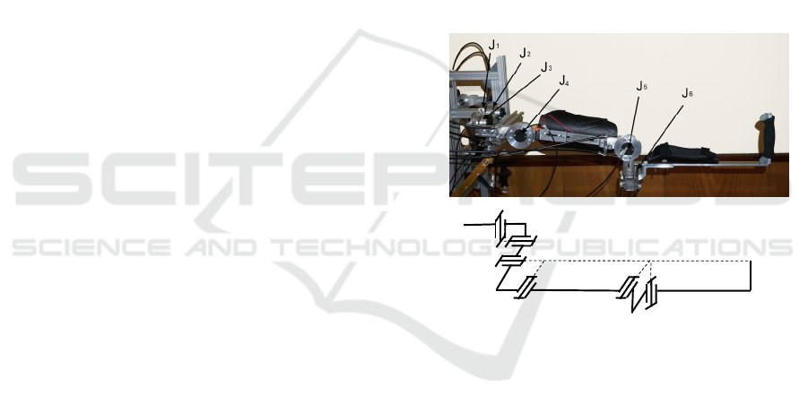
fixed base. The exoskeleton mechanical structure
includes two identical arms. Each arm includes pairs
of identical rotational joints for clavicle movements
J1, J2, shoulder movements J3, J4 and elbow
movements J5, J6 respectively, as shown in Figure 1
a), b). Each arm has a total of 6 degrees of mobility,
mimicking the natural movement of the human arm
from back to elbow. The structure of Figure 1 was
selected for designing the arm exoskeleton using
uniform universal joints and thus more complex
solutions involving circular guide and triaxial joints
are avoided.
a)
b)
6
2
0
J1
J2
J3
J4 J5
J6
1
3
4
5
EE
Figure 1: Exoskeleton right arm: a) prototype; b) structural
scheme.
Each arm of the exoskeleton consists of six
movable segments (1, 2, 3, 4, 5 and 6) made primarily
of aluminum alloy. Plastic shells with straps are
placed on the segments for attachment to the human
limb (Figure 1a). The generalized masses of the six
segments of the arm are M
1
= 0.463 kg, M
2
= 0.321
kg, M
3
= 0.497 kg, M
4
= 0.782 kg, M
5
= 0.510 kg and
M
6
= 0.793 kg. The arm and forearm lengths of the
exoskeleton were set with initial values L
1
= 0.286 m
and L
2
= 0.370 m. The range of motion in the joints is
as follows: J
1
(15°),J
2
(15°),J
3
(120°), J
4
(120 °), J
5
(150 °), J
6
(135 °). The range of movements in the
joints is tailored to that in the joints of the human arm,
as shown in (Abane, 2016).
Light drive units integrating pneumatic cylinders
and cable transmissions are used to drive the
ICINCO 2022 - 19th International Conference on Informatics in Control, Automation and Robotics
404
exoskeleton joints. The drive unit of each exoskeleton
joint is built as a separate unit located in the fixed
base. A diagram of the drive unit is shown in Figure
2. The base has a bearing wheel 1 with a cable reel R1
mounted thereon. Bowden cables T1, T2 are used to
connect the reel R1 and a similar reel R3, located in
the exoskeleton joint. A high-precision rotary sensor
is installed in the joint to measure the effective
deviation.
Figure: 2: Scheme of pneumatic drive of the exoskeleton
joints.
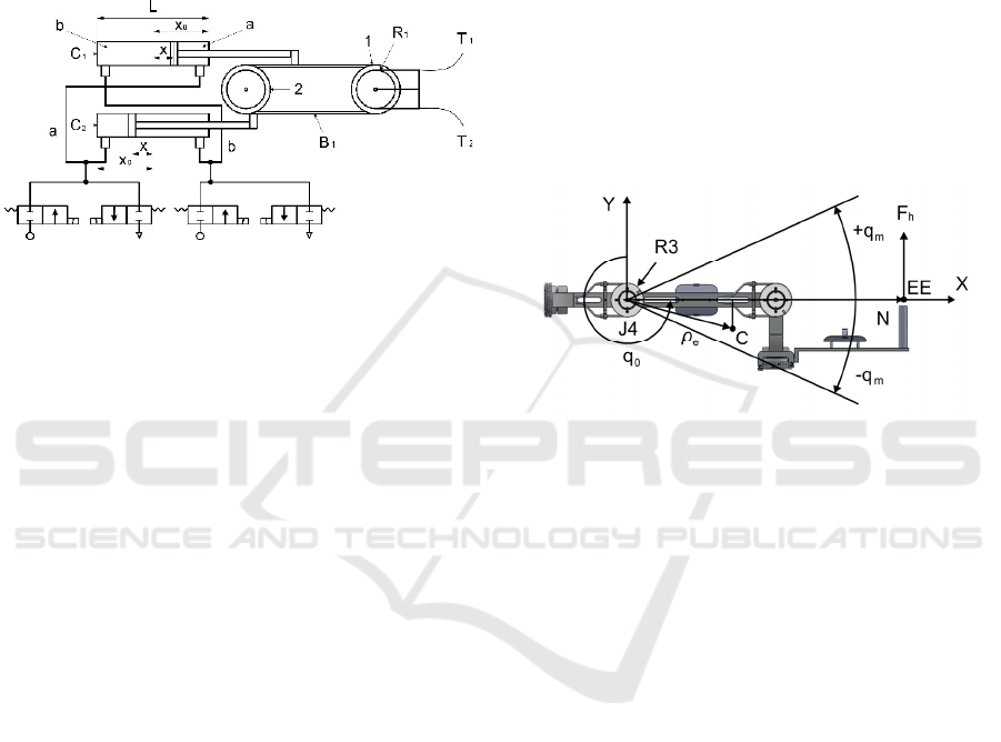
The pneumatic actuator consists of a pair of
pneumatic cylinders, C1 and C2, mounted in the base
as shown in Figure 2. Pneumatic cylinders with
diameter D = 0,02 m were used. A transmission was
used, including timing belt B1 and additional wheel 2
to transmit movement from pneumatic cylinders to
wheel 1. The cylinders simultaneously drive opposite
sides of the belt B1. The left-hand chamber of one
cylinder is connected to the right-hand chamber of the
other cylinder by piping, and the other right-hand and
left-hand chambers are connected by other piping
(Figure 2). The piping of each pair is connected to two
parallel valves, one of which supplies pressure air to
the chambers and the other of which connects the
chambers to atmospheric pressure. Pressure sensors
are mounted on each line.
In the work, the interaction between the patient
and the exoskeleton is evaluated in the so-called
"patient in charge" modes, when the patient is able to
initiate complex independent movement in a
relatively safe manner, where it is important that the
interaction forces between the exoskeleton and the
patient are low.
Different approaches are used to study human-
robot interaction. They are all built on the connection
between human behavior and the abilities of the
robot. For example, in (Melchiorre M., 2018) the
robot monitors the position of the human operator's
hand and moves its end effector to reach the operator's
hand.
To assess the interaction forces, experiments are
performed with motion in one joint of the
exoskeleton, similar to the approach used in (Bembli
S., 2019). All joints are locked and the J4 joint is
mobile where flexion-extension is performed in the
shoulder. The patient moves the arm on the
exoskeleton applying force in the end effector (EE)
normal to the arm. This force is the subject of
assessment in the present work.
The patient performs harmonic motions from an
initial position q
0
with uniform amplitude q
m
and
constant oscillation frequency ω. The angle q at joint
J4 determines the arm position, assuming q = 0 when
the arm is coincident with the y-axis (Figure 3). The
following law of motion is used to model the
harmonic motions
0m
q)tsin(qq
(1)
Figure: 3: Exoskeleton joint J4 performing harmonic
motion with amplitude q
m
from starting position q
0.
The assessment of the interaction forces is carried
out in a passive regime. In passive mode, the
exoskeleton does not generate active forces. The
resisting forces are determined only by the
mechanical impedance of the exoskeleton. The EE
force applied to the operator's arm, which overcomes
the mechanical impedance of the exoskeleton, is
determined by the inertial, frictional and gravitational
forces as well as the elastic forces of the pneumatic
actuation. In the present study, a low dynamic mode
is applied in which only the influence of gravitational
and elastic forces is considered. The EE force F
h
applied to the patient's arm is the sum of the forces
from gravity F
g
and the forces from the pneumatic
actuation F
p
applied to the end effector according to
equation:
pgh
FFF
(2)
where
N/QF
e
gg
(3)
N/QF
pp
. (4)
Above:
Q
e
g
is the torque created by the exoskeleton
gravity according to the equation
Comparative Study of a Vacuum Powered Upper Limb Exoskeleton
405

)qcossinqg(MQ
e2e1e
e
g
(5)
where: M
e
represents the mass of exoskeleton moving
parts 4, 5, 6; ρ
e
=[ρ
e1
; ρ
e2
]
T
represents the radius
vector of the mass center C in а local frame and g is
the gravity acceleration coefficient;
Q
p
is the torque produced by the forces in the two
pneumatic cylinders, represented by the sum
r))s(sp-)s(sp(Q
21b21ap
(6)
where p
a
and p
b
are the supply pressures in both
chambers, r is the radius of reel R1 and s
1
and s
2
are
the areas on both sides of the piston;
N is the value of the radius vector of the EE.
In the passive mode, to provide transparency of
gravity, the torque generated by the pneumatic
cylinder forces Q
p
is used to compensate the torque
from the gravitational forces Q
e
g
. For this reason, one
of the chambers of the pneumatic cylinders is
supplied with an appropriate pressure, after which the
inputs and outputs of this chamber are closed. The
second chamber of the pneumatic cylinders is open to
the atmosphere. In this case, the torque Q
p
is
determined by the elastic forces in the closed chamber
due to air compression.
Assuming that air is an ideal gas undergoing an
isothermal process (Czmerk, A., 2017), the rate of
pressure change p and volume change V in a closed
chambers of the cylinder can be expressed by the
polytrophic process equation
CVp
(7)
where C is a constant.
Once in the starting position of the cylinders X
0
(Figure 2), chamber a of the pneumatic cylinders is
closed with a pressure p
0
(a)
and the volume V
(a)
of the
chamber is represented as a function of piston area
and chamber length, equation (7) takes the form:
a210
0
(a)
C)ss(Xp
(8)
where s
1
and s
2
are the areas on both sides of the
piston and C
a
is a constant.
After the patient performs motions according to
the scheme of Figure 3, the piston makes a deviation
x from starting position X
0
(Figure 2) and the pressure
p
a
in the closed chamber changes. Then equation (8)
allows the new equality to be displayed:
a210a210
0
(a)
C)ss)(xX(p)ss(Xp
(9)
Then, equality (9) give the equation for the variation
of the pressure p
a
depending on the piston deviation x
xX
Xp
p
0
0
0
a
a
(10)
When chamber a is closed and chamber b open to
the atmosphere or p
b
= p
atm
, according to (6) and (10),
the equality of elastic actuator torque as a result of the
pistons deviation x from the starting position X
0
is
derived
)rs](sp-
xX
Xp
[Q
21atm
0
0
0
a
pa
(11)
When in the starting position of the cylinders X
0
chamber b is closed with a pressure p
0
(b)
and chamber
a is open to the atmosphere, after that the patient
performs motions and the piston makes a deviation x
from starting position X
0
, (Figure 2), еquation (7)
allows the following equalities to be compiled
b210
b
210
0
b
C)ss)(xXL(p
)ss)(XL(p
(12)
xX-L
)X-(Lp
p
0
0
0
b
b
(13)
where L is the cylinder length and C
b
is a constant.
In this case where p
a
= p
atm
according to (6) and
(13) the equality of elastic actuator torque is as
follows
)rs](s
xX-L
)X-(Lp
-p[Q
21
0
0
0
b
atmpb
(14)
As the initial position of the arm q
0
corresponds to
the starting position X
0
of the cylinders, the piston
deviation x, is determined by the deviation q of the
joint angle, as follows
q
r
x
(15)
The behavior of closed pneumatic cylinders
according to (11) and (14) behaves like a variable
compliance spring. The stiffness of the joint driven
by pneumatic cylinders can be determined as a
derivative of the joint torques (11) and (14) about the
joint deviation, according to the equality:
q
x
x
Q
q
Q
K
)b,a(p)b,a(p
)b,a(
( 1 6 )
After differentiating equations (11) and (14),
taking into account that p
atm
=const, p
a
0
=const,
p
b
0
=const and that piston displacement x is a linear
ICINCO 2022 - 19th International Conference on Informatics in Control, Automation and Robotics
406
function (15) of the articular displacements q, it
follows
2
21
2
0
0
0
a
a
)rs(s
x)(X
Xp
K
(17)
2
21
2
0
0
0
b
b
)rs(s
)xX-(L
)X-(Lp
K
(18)
The stiffness of the joint when a chamber is
closed and the other is open to the atmosphere
according to (17) and (18), represents a linear
function of the initial pressure in the closed chamber
and a nonlinear function of the piston displacements.
In the present study, the objective is to evaluate
the interaction force at the end effector as a result of
pneumatic actuation with pressures higher and lower
than atmospheric pressure. Therefore, two cases are
considered: first, when the pressure p
0
(a)
in chamber
a is greater than atmospheric pressure, and chamber b
is open to the atmosphere (p
b
= p
atm)
; second, when
chamber а is open to the atmosphere (p
a
= p
atm
), and
the pressure p
0
(b)
in chamber b is less than
atmospheric pressure or vacuum pressure.
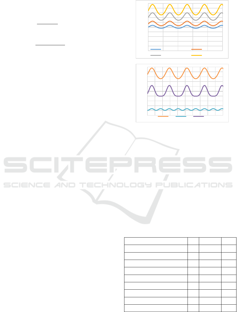
3 RESULTS
3.1 Interaction Force at the End
Effector as a Result of Pneumatic
Actuation with Pressure Higher
than Atmospheric Pressure
In this experiment, the initial pressure in chamber a
takes on the following values equal to or greater than
atmospheric pressure: p
0
(a)
= 100, 150, 250, 350 kPa.
Chamber b is open to the atmosphere and has a
constant pressure p
b
= p
atm
=100kPa. The other
parameters of the pneumatic drive are shown in Table
1. Since chamber a is closed, it is a generator of
elastic force. The initial position of the arm is q
0
=
270
0
(Figure 3) and the selected starting position of
the piston is X
0
= 0.0625 m. The maximum deviations
of the arm from the starting position equal to q
m
= 25
0
correspond to the deviations of the piston from the
starting position equal to x = 0.014 m. When the arm
oscillates according to (1), the elastic moment (11) is
calculated and is brought to the end effector, where it
forms the resistance force from the pneumatics (4).
The results of this experiment are shown graphically
in Fig.4 a).
a)
b)
Figure 4: Interaction force at the end effector as a result of:
a) pneumatic (F
p
) with pressures p
0
(a)
= 100, 150, 250, 350;
b) gravity (F
g
); pneumatic (F
p
) with pressure p
0
(a)
= 350
kPa and resulting force (F
p
+ F
g
).
In order to use the force from the pneumatic drive
as a balancer of the force from the exoskeleton gravity
according to (2), a pressure in chamber a equal to p
0
a
= 350 kPa is selected. The aim is to increase the
transparency or to bring the force applied to the
operator's arm closer to 0. At the same starting
position and the same arm movements as in the
previous experiment, the change in gravitational force
(3) and pneumatic force (4) was calculated. Graphs
with the variation of these forces, as well as with the
resulting force (2), are shown in Fig.4 b).
Table 1: Pneumatic drive parameters.
Piston area side 1
s
1
314 10
-6
m
2
Piston area side 2 s
2
264 10
-6
m
2
Pneumatic cylinder diameter D 0.020 m
Pneumatic cylinder stroke L 0.125 m
Piston starting position X
0
0.0625 m
Exoskeleton mass M
e
2.085 kg
Radius of EE N 0.660 m
Radius of pulley 1 r 0.0315 m
Coordinate 1 of mass center ρ
e1
0.256 m
Coordinate 2 of mass center ρ
e2
0.031 m
‐10
‐8
‐6
‐4
‐2
0
2
4
6
8
10
0246810
[N]
[s]
Fp
pa=100kPa pa=150kPa
pa=250kPa pa=350kPa
‐10
‐8
‐6
‐4
‐2
0
2
4
6
8
10
012345678910
[N]
[s]
Fp Fg Fp+Fg
Comparative Study of a Vacuum Powered Upper Limb Exoskeleton
407

3.2 Interaction Force at the End
Effector as a Result of Pneumatic
Actuation with Pressures Lower
than Atmospheric Pressure
In the experiment, the chamber a of the pneumatic
cylinders is connected to the atmosphere, therefore it
has a constant pressure p
a
= p
atm
=100 kPa. The initial
pressure in chamber b acquires the following values
less than or equal to atmospheric pressure: p
0
(b)
= 0,
14, 40, 70, 100 kPa. Since chamber b is closed, it is a
generator of elastic force. When p
0
(b)
= 0 (vacuum),
according to (14) the actuator torque reaches its
maximum value Q
p
max
which is constant and does not
depend on the deviations of the piston position.
.constr))s(spQ
21atm
max
p
(19)
The maximum torque determined by the constant
atmospheric pressure may not be sufficient to drive
the designed device. For this reason, the vacuum-
powered exoskeleton needs to change some of the
other parameters, such as the face of the pistons.
Thus, larger pneumatic cylinders with diameter D
= 0.035 m and piston area (s1 + s2) = 0.001840 m
2
were selected for vacuum pressure drive. The values
of the other parameters of the pneumatic drive are
those of Table 1.
The experiment was performed with the same arm
movements: starting position q
0
= 270
0
and maximum
deviations q
m
= 25
0
. When the arm oscillates
according to (1), the elastic moment (14) is
calculated, which is reduced to the end effector as the
interaction force from the pneumatic actuation (4).
The results of this experiment are shown graphically
in Fig.5 a).
In order to balance the gravity of the exoskeleton
with the pneumatic drive according to (2), chamber
pressure, p
0
b
=14 kPa is chosen, so that the force
applied to the operator's arm is equal to 0. At the same
starting position and arm movements the force (2) is
calculated. The change of this force, as well as of the
gravitational force (3) and of the pneumatic drive
force (4) are shown in the graph in Fig.5 b).
4 DISCUSSION
In the experiments performed, the interaction force in
the passive mode of interaction is evaluated, as this
force represents the initial reaction of the
exoskeleton, which can then be changed by the active
mode. Static forces in the interaction such as gravity
resistance and propulsion resistance are evaluated.
a)
b
)
Figure 5: Interaction force at the end effector as a result of:
a) pneumatic actuation (F
p
) with vacuum pressures p
0
(b)
= 0,
14, 40, 70, 100 kPa ; b) gravity (F
g
); pneumatic (F
p
) with
pressure p
0
(b)
= 14 kPa and resulting force (F
p
+ F
g
).
When the pneumatic drive uses positive pressure,
the compressed gas creates an elastic resistance force,
which is greater at higher pressures and is close to 0
when the pressure in the closed chamber is equal to
atmospheric (Fig. 4a). Pneumatic actuation can
compensate for gravity by appropriate pressure in the
chambers, but deviations from the equilibrium
position lead to resistance fluctuations due mainly to
the increased pressure and increased stiffness of the
compressed gas (Fig. 4b). The advantage here is the
theoretically unlimited magnitude of the driving
force.
When the pneumatic drive uses vacuum pressure,
the resistance force depends less on the imposed
deviations. In this case, when the vacuum pressure
approaches zero, the drive force increases, and the
stiffness of the drive decreases (Fig.5a). This leads to
a constant resistance force, independent of the
imposed deviations. If gravity is compensated by a
vacuum pressure close to 0, in the case of deviations
from the equilibrium position, the force of interaction
remains almost constant, and small deviations are the
result of changes in the moment of gravity (Fig.5b).
The main advantage of the vacuum drive is the low
stiffness of the drive, which reaches its minimum
when the driving force is highest. The disadvantage
of this approach is the limitation in the maximum
value of driving force. This can be corrected by
‐10
‐8
‐6
‐4
‐2
0
2
4
6
8
10
0246810
[N]
[s]
F
p
pb=0 pb=14kPa
pb=40kPa pb=70kPa
pb=100kPa
‐10
‐8
‐6
‐4
‐2
0
2
4
6
8
10
0246810
[N]
[s]
Fp Fg Fp+Fg
ICINCO 2022 - 19th International Conference on Informatics in Control, Automation and Robotics
408

increasing the active area of the pneumatic actuator
on which the atmospheric pressure acts. However, the
increased area leads to a change in other mechanical
parameters.
5 CONCLUSION
In the present work, an exoskeleton of the upper limb
intended for rehabilitation and training is studied. The
aim of the work is to find and evaluate an appropriate
exoskeleton solution that provides performance on
the one hand and transparency and natural safety on
the other. Therefore, a pneumatic drive is proposed in
the work, which is evaluated by comparing the
positive pressure drive with the vacuum pressure
drive. To assess transparency, the interaction force
between the patient and the exoskeleton in passive
mode is examined.
Simulations were performed with harmonic
movement imposed by the patient in one joint of the
exoskeleton. The interaction force between the
patient and the exoskeleton was assessed as a result
of the gravity of the exoskeleton and the pneumatic
force. In this case, the torque generated by the elastic
forces in the closed chamber of the pneumatic
actuators is used to compensate for the torque due to
gravity. The interaction force at the end effector is
estimated for cases of pneumatic propulsion with
pressure higher than atmospheric and with vacuum
pressure.
Assessments show that an increase in positive
pressure leads to increased stiffness and higher values
of the interaction forces. This allows for better
efficiency when performing operations in "robot in
charge" mode. Vacuum pressure reduces stiffness and
leads to small deviations in the interaction force and
from there to higher transparency and patient safety.
However, low stiffness is associated with a weak
force response and low efficiency.
The combination of safety requirements on the
one hand and the efficiency requirements on the other
can be achieved through pneumatic actuators that
allow a wide range of control pressures. The subject
of the future work of the authors is the development
and experimentation of pneumatic drive, which
allows adjusting the stiffness in a wide range.
ACKNOWLEDGEMENTS
This work has been accomplished with the financial
support by the Grant No BG05M2OP001-1.002-
0011-C02 financed by the Science and Education for
Smart Growth Operational Program (2014-2020) and
co-financed by the European Union through the
European structural and Investment funds.
REFERENCES
Manna S. K., Dubey V. N., (2018). Comparative study of
actuation systems for portable upper limb exoskeletons,
Medical Engineering and Physics, 60, 1–13.
Jarrasse, N., T. Proietti, et al., (2014). Robotic
Exoskeletons: A Perspective for the Rehabilitation of
Arm Coordination in Stroke Patients, Frontiers in
Human Neuroscience, Vol.8, Art.947, 1-13.
Veneman, J.F., R. Ekkelenkamp, et al., (2006). A series
elastic- and bowden-cable-based actuation for use as
torque actuator in exoskeleton-type robots, The Int.
Journ. of Rob. Research, vol. 25(3), 261-281.
Courtois G., Chevrie J., Dequidt A., Bonnet X. and Pudlo
P. (2021). Design of a Rehabilitation Exoskeleton with
Impedance Control: First Experiments. Proc.of the
18th Int. Conf. on Informatics in Control, Automation
and Robotics – ICINCO 2021, 469-476. DOI:
10.5220/0010580004690476.
Morales R., et al., (2011). Pneumatic robotic systems for
upper limb rehabilitation, Med. Biol. Eng. Comput. 49,
1145–1156.
Daerden Fr. and Lefeber D., (2002). Pneumatic Artificial
Muscles: actuators for robotics and automation. Europ.
J. of Mech. and Environmental Engineering; 47,1:1–11.
Nikolov S., V. Kotev, K. Kostadinov, F. Wang, C. Liang,
and Y. Tian, (2016). Model-based design optimization
of soft fiber-reinforced bending actuators," in Proc.
IEEE Int. Conf. Manipulation, Manuf. Meas.
Nanoscale, pp. 136-140.
Yang D., M. S. Verma, E. Lossner, D. Stothers, G. M.
Whitesides, (2017). Negative-pressure soft linear
actuator with a mechanical advantage. Adv. Mater.
Technol., vol.2, issue 1, pp.1600164 1-6.
Matthew A., Robertson and Jamie Paik, (2017). New soft
robots really suck: Vacuum-powered systems empower
diverse capabilities. Science Robotics, vol. 2, no.9, 30.
August 2017, doi: 10.1126/scirobotics.aan6357.
Mendoza Mijaíl Jaén, Samuel Dutra Gollob, Diego Lavado,
Bon Ho Brandon Koo, Segundo Cruz, Ellen T. Roche
and Emir A. Vela, (2021). A Vacuum-Powered
Artificial Muscle Designed for Infant Rehabilitation.
Micromachines, 12 (8), 971. doi: 10.3390/mi12080971.
Tawk, C., Spinks, G. M., in het Panhuis, M. & Alici, G.
(2019). 3D Printable Linear Soft Vacuum Actuators:
Their Modeling, Performance Quantification and
Application in Soft Robotic Systems. IEEE/ASME
Transactions on Mechatronics, 24 (5), 2118-2129.
Chakarov D., Veneva I., Tsveov M., Mitrouchev P., Venev
P. (2019), Design of a Two Arms Exoskeleton as Haptic
Device for Virtual Reality Applications, Lecture Notes
in Mech. Eng., Springer Nature, Chapter 25, 252-262.
Comparative Study of a Vacuum Powered Upper Limb Exoskeleton
409

Chakarov, D., Veneva, I., Venev, P., Tsveov M, (2021).
Evaluation of the capabilities of a hybrid driven
exoskeleton in passive mode of interaction. Pros of the
18th Int. Conf. on Informatics in Control, Automation
and Robotics, ICINCO 2021, 442-449. DOI:
10.5220/0010569004420449
Abane A., Guiatni M., Fekrache D., Merouche S., Otmani
A., Tair M. and Ababou N. (2016). Mechatronics
Design, Modeling and Preliminary Control of a 5 DOF
Upper Limb Active Exoskeleton. Proc. of the 13th Int.
Conf. on Informatics in Control, Automation and
Robotics – Vol. 2: ICINCO 2016, 398-405. DOI:
10.5220/0005984203980405.
Melchiorre M., Sabatino Scimmi L., Mauro S. and
Pastorelli S. (2018). Influence of Human Limb Motion
Speed in a Collaborative Hand-over Task. Proc. of the
15th Int. Conf. on Informatics in Control, Automation
and Robotics – Vol. 2: ICINCO 2018, 349-356. DOI:
10.5220/0006864703490356
Bembli, S., Haddad, N. and Belghith, S., (2019). A
Terminal Sliding Mode Control using EMG Signal:
Application to an Exoskeleton- Upper Limb System.
Proc. of the 16th Int. Conf. on Informatics in Control,
Automation and Robotics, Vol.2: ICINCO 2019, 559-
565. DOI: 10.5220/0008071905590565
Czmerk, A., A. Bojtos, (2017). Stiffness investigation of
pneumatic cylinders, 59th Ilmenau Scientific
Colloquium, Technische Universität Ilmenau, 11 – 15
September, 2017, 1-7, URN: urn:nbn:de:gbv:ilm1-
2017iwk-148:6.
ICINCO 2022 - 19th International Conference on Informatics in Control, Automation and Robotics
410
