
Study on Effect of Material Layer Thickness on Pollutant Emissions
from Sintered Flue Gas
Chen Zhang
a
, Yutao Cui
b
, Yun Shu
c
, Li Yang
*d
and Jinwei Zhu
*e
Chinese Research Academy of Environmental Sciences, Beijing 100012, China
Keywords: Sintered, Flue Gas, Emission, Material Layer.
Abstract: Herein, a 210-m
2
sintering machine was tested under different material layer thickness conditions to
investigate the effect of the thick layer sintering technology on the emissions of flue gas pollutants from the
sintering machine. The relationship between the material layer thickness and pollutant emission
concentration, sinter output and drum index was studied using a flue gas analyser (MH3200). The results
show that the discharge of gaseous pollutants has a positive linear correlation with the material layer
thickness during the sintering process of SO
2
, NO and CO. Furthermore, the emission of pollutants per
tonne of product decreases as the layer thickness increases. When the thickness of the material is increased
from 550 to 650 mm, the emissions of SO
2
, NO and CO per tonne of the sintered ore can be reduced by
0.22, 0.07 and 1.7 kg/t, respectively.
1 INTRODUCTION
1
As a major steel country, China’s steel industry
output has ranked first in the world for many years.
According to statistics from the China Iron and Steel
Association, China’s steel output exceeded 900
million tonnes in 2018, accounting for 50% of the
world’s steel output. The iron and steel industry is
an industry with high energy consumption and high
pollution. Besides, environmental pollution has
received much attention. With the continuous
deepening of pollution control work requirements in
China’s iron and steel industry, the industry has
shifted from the traditional mode of re-production
and high-efficiency to the direction of production
and environmental protection. However, the steel
industry has become the largest source of gaseous
pollutants due to several companies, the large
amount of pollutant emissions and the uneven level
of corporate management and environmental
protection. In 2017, sulphur dioxide (SO
2
), nitrogen
oxide (NOx) and particulate matter (PM) emissions
a
https://orcid.org/0000-0003-1347-1824
b
https://orcid.org/0000-0003-0091-7612
c
https://orcid.org/0000-0002-7575-5956
d
https://orcid.org/0000-0003-0021-0166
e
https://orcid.org/0000-0003-4034-736X
from the iron and steel industry accounted for 7%,
10% and 20% of the total national emissions (Li
2018, Yan 2015, Yu 2017). For this reason, in 2019
the ‘Opinions on Promoting the Implementation of
Ultra-Low Emissions in the Iron and Steel Industry’
jointly issued by the Ministry of Ecology and
Environment and other five ministries and
commissions included access to new reconstruction
and expansion projects of iron and steel enterprises,
the promotion of ultra-low emission transformation,
the elimination of outdated production capacity and
the strengthening of pollution emission monitoring
and monitoring new corresponding requirements put
forward in other aspects.
The iron and steel industry mainly adopts the
conventional blast furnace converter technology in
China. The sintering process, which is an important
link in steel production and also the main process for
emitting gaseous pollutants in iron and steel
enterprises (Liao 2018, Wang 2013, Zhu 2014),
provides more than 70% of the charge to the blast
furnace. Sintering flue gas has the characteristics of
large flue gas volume and high pollutant
concentration. According to relevant literature
reports, the emission of SO
2
, NOx and PM in the
sintering process can account for ~60%, 50% and
20% of the total emissions of iron and steel
enterprises (Wang 2017, Chen 2015, Taira 2019).
Among them, SO
2
in the flue gas of the sintering
448
Zhang, C., Cui, Y., Shu, Y., Yang, L. and Zhu, J.
Study on Effect of Material Layer Thickness on Pollutant Emissions from Sintered Flue Gas.
DOI: 10.5220/0011215600003443
In Proceedings of the 4th International Conference on Biomedical Engineering and Bioinformatics (ICBEB 2022), pages 448-454
ISBN: 978-989-758-595-1
Copyright
c
2022 by SCITEPRESS – Science and Technology Publications, Lda. All rights reserved

machine mainly comes from the sulphides (such as
FeS
2
and CuFeS
2
) and sulphates (such as BaSO
4
and
CaSO
4
) in the iron ore, and partly comes from the
elemental and organic sulphur in the fuel. Note that
the elemental sulphur is the main component.
Sulphide reacts with organic sulphur and oxygen to
generate SO
2
, which is released after sulphate
decomposition. The NO
x
from the combustion
process is mainly divided into three types: thermal,
fuel and fast types. (1) Thermal-type nitrogen oxides
are generated by the reaction of N
2
and O
2
in air
during combustion. (2) Fuel-type nitrogen oxides are
generated by the oxidation of N in the fuel during
combustion. (3) Rapid nitrogen oxides are produced
by the reaction of N
2
in air with hydrocarbon groups
in the fuel to generate HCN, CN and other NO
precursors, which are then further oxidised. During
sintering, the combustion temperature is <1500°C,
and the thermal NO
x
is minute. Therefore, the NO
x
in the flue gas of the sintering machine mainly
comes from the combustion process of solid fuel,
that is, fuel-based NO
x
, usually >90% of NO
x
. CO
generation mainly comes from the incomplete
combustion of solid fuels in the sintering process,
mainly in the combustion zone and the preheating
drying zone. Also, the reaction of C with CO
2
and
Fe will also generate CO (Liu 2013, Williams 2012,
Li 2014).
Presently, treatment technology for sintering
machine flue gas is mainly divided into three
categories: raw material control, sintering process
control and end flue gas treatment technology (Chun
2017, Xing 2014). The end treatment technology
mainly adopts the FGD + SCR denitrification
technology. Among them, the desulphurisation
technology mainly applies to wet desulphurisation
and semi-dry desulphurisation. A few companies
adopt the activated carbon adsorption-integrated flue
gas purification technology. These treatment
technologies can effectively control the SO
2
and
NO
x
emission in the flue gas. However, with the
implementation of ultra-low emission standards in
the steel industry, the ultra-low emission of sintering
flue gas through the upgrading and transformation of
desulphurisation and denitrification facilities will
significantly increase the production of enterprises.
Operating costs are not conducive to the long-term
development of enterprises (Long 2016, Wang 2020,
Cheng 2019). Faced with dual pressures of
production and environmental protection, several
new sintering technologies for energy saving and
emission reduction have emerged, such as thick
material layer sintering technology, combustible gas
auxiliary combustion technology, fuel distribution
technology, material surface steam injection
technology and low-temperature sintering
technology, Hot air circulation sintering technology
has been widely used in the actual production
(Huang 2019, Zhang 2019, Fan 2014, Lu 2015).
Herein, the influence of the material layer thickness
changes on the emission of pollutants is studied
using the actual flue gas. The current research in this
direction is mainly focused on the impact of the
material layer thickness on the production cost of the
sintering machine and the improvement of the
quality of the sintered ore. However, few studies
exist on the gaseous pollutant emission of the
sintering machine, and the research is mainly limited
to the sinter cup test—actual on-site monitoring. To
deeply analyse the influence of the material layer
thickness on the air pollutant emission from the
sintering machine, a sintering machine with a scale
of 210 m
2
of a certain enterprise was selected as the
experimental platform, and the NO, SO
2
, CO and
other pollution in the airbox and sintering flue of the
sintering machine. The changes in the concentration
of the substances and O
2
before and after the
changes in the material layer thickness are
monitored and analysed to clarify the changing law
of gaseous pollutant emissions from the sintering
machine under different material layer thicknesses
and provide data support for the subsequent
environmental protection of the flue gas of sintering
machines.
2 MATERIALS AND METHODS
2.1 Sintering Machine Parameters
Herein, a 210-m
2
sintering machine was selected as
the research object for industrial testing. The
composition analysis of 22 wind boxes and sintering
flue gas on one side of the sintering machine was
performed. Figure 1 shows the monitoring points.
By changing the material layer thickness of the
sintering machine (550 mm × 600 mm × 650 mm),
the pollutant emission was analysed. Table 1
presents the main chemical components of the
sintering raw materials.
Study on Effect of Material Layer Thickness on Pollutant Emissions from Sintered Flue Gas
449
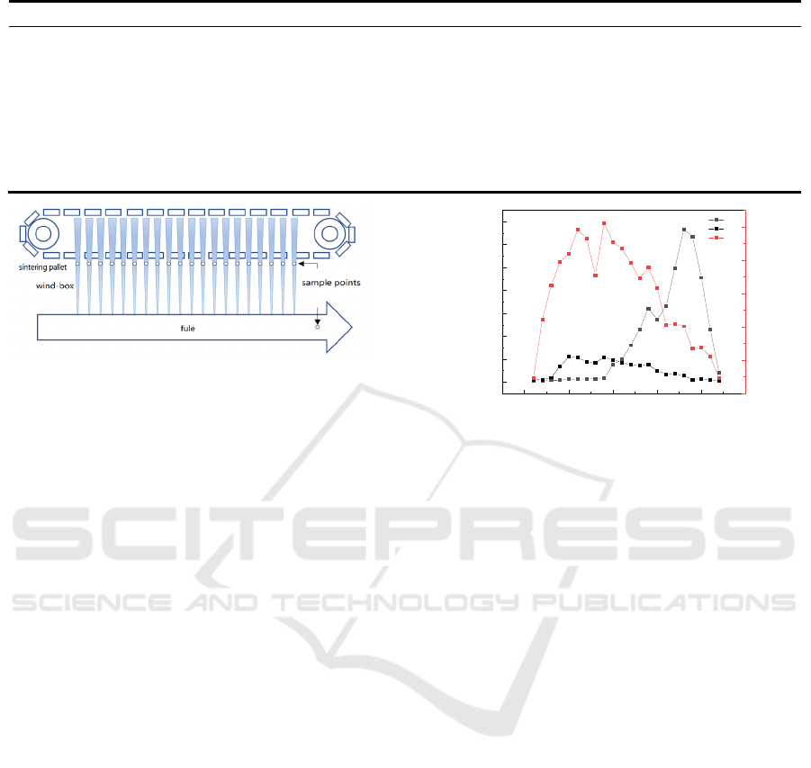
Table 1: Chemical composition of main raw materials.
Raw material TFe SiO
2
CaO Al
2
O
3
MgO H
2
O
Iron sheet 71.00 0.80 - 0.00 - 8.00
Dolomite powder - 2.50 30.00 - 20.00 3.00
Limestone powder 0.00 3.00 47.00 0.00 4.50 3.00
Miscellaneous 50.00 6.60 12.80 2.60 2.80 6.00
Mixed return mine 54.60 5.40 10.60 2.60 2.80 2.00
Steel slag 35.00 12.00 35.00 - 9.93 6.00
Coke breeze 0.00 40.00 7.00 1.60 - 10.00
Figure 1: Schematic of monitoring locations.
2.2 Detection Equipment and Methods
Qingdao Minghua Electronic Instrument Co., Ltd.
MH3200 ultraviolet differential method flue gas
analyser was was used. It adopts ultraviolet
differential absorption spectroscopy measurement.
The principle is thermal wet method, the whole
process of the gas chamber-heating design, the flue
gas is extracted from the flue after several grades of
filtration, enter the optical detection gas chamber,
the entire gas path is heated at high temperature, and
the water vapour is completely vaporised, avoiding
the interference of moisture on the gas adsorption.
3 RESULTS & DISCUSSION
3.1 Regular Distribution of Pollutants
in Wind Boxes
The material layer thickness of the sintering machine
as 600-mm (daily conditions) is selected as the
reference-working condition. Next, the distribution
law of the air box pollutants is analysed. Using the
same monitoring programme, under the premise of
maintaining a constant raw material ratio, the wind
box and sintering flue gas under the working
conditions of 550 and 650 mm material layer
thickness were detected. Figure 2 shows the change
in the wind box.
0 5 10 15 20 25
0
200
400
600
800
1000
1200
1400
SO
2
NO
CO
Wind boxes number
SO
2
/NO
(
mg/m
3
)
0
5000
10000
15000
20000
25000
CO
(
mg/m
3
)
Figure 2: Distribution of smoke components in wind boxes.
3.1.1 SO
2
Emission Regular Analysis
Figure 2 shows that SO
2
emissions can be divided
into three distinct characteristic intervals during the
entire sintering process. The first interval is before
the 9
th
wind box, and the SO
2
emission concentration
in each wind box is low, all below 35 mg/m
3
. The
second interval started from the 10
th
wind box; the
SO
2
emission concentration increased obviously,
after nine wind boxes, it culminated at the 18
th
wind
box position 1335 mg/m
3
). Afterwards, there comes
the third interval, where the SO
2
emission
concentration decreased rapidly. After passing
through four wind boxes, the concentration
decreased to 100 mg/m
3
. This trend can be ascribed
to the fact that SO
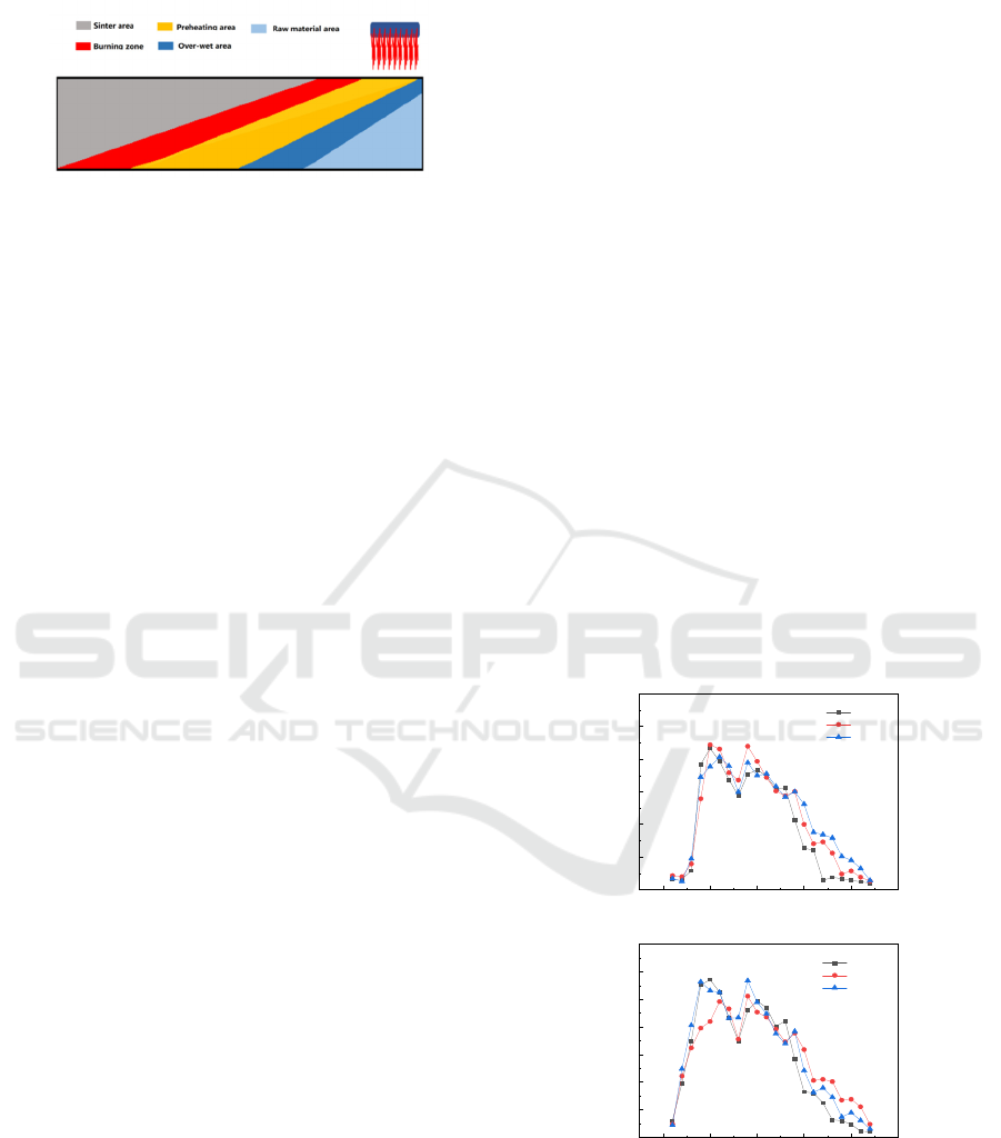
2
is mainly generated in the
combustion and dry preheating zones (Figure 3
shows the schematic of the change in the sintered
material layer), and its formation mechanism is the
oxidation reaction of sulphide, elemental sulphur
and sulphate. After preheating and decomposition,
SO
2
will be absorbed again, forming sulphate and
sulphide due to the joint action of alkaline flux and
moisture when passing through the over-humid zone
as the flue gas moves from top to bottom. During
sintering, the over-humidity zone gradually
disappears, and SO
2
is released into the flue gas
again. When the combustion zone disappears, the
SO
2
emission concentration decreases rapidly, thus
forming this emission characteristic. The results are
ICBEB 2022 - The International Conference on Biomedical Engineering and Bioinformatics
450
consistent with those of previous studies (Wang
2019, Fan 2019).
Figure 3: Schematic diagram of material layer changes.
3.1.2 NO Emission Regular Analysis
The emission concentration of NO
2
in each wind
box was <5 mg/m
3
, so the emission characteristics of
NO
x
and NO were consistent. Thus, the emission
characteristics of NO needed to be analysed only.
Figure 2 shows that NO emissions have three
distinct characteristic intervals. The first interval is
before the 4
th
wind box, and the NO emission
concentration is below 40 mg/m
3
. Afterwards, the
second interval starts from the 4
th
wind box. The
concentration increased significantly and culminated
at 219.8 mg/m
3
in the 9
th
bellows, and the third
interval comes afterwards, and the NO concentration
decreased slowly. On reaching the 22
nd
bellows, its
emission concentration was close to 10 mg/m
3
. This
emission law is caused because NO produced during
the sintering process is basically the fuel-type NO,
and the concentration depends on the combustion
state. At the beginning of sintering, the combustion
zone is small, so the NO emission concentration is
low. As the sintering progresses, the combustion
zone gradually stabilises, and NO emission
concentration tends to stabilise after increasing.
Towards the end of the sintering process, the
combustion zone gradually decreases, and the NO
emission concentration gradually decreases (Min
2016, Zhou 2016).
3.1.3 CO Emission Regular Analysis
Figure 2 shows that the first characteristic interval of
CO emissions occurs before the 5
th
wind box. At this
stage, the CO concentration in the flue gas rapidly
increases above 20000 mg/m
3
. The second
characteristic interval occurs from the 5
th
–11
th
box.
In this interval, the CO concentration is above 20000
mg/m
3
, and the concentration of the 9
th
bellows is
the highest at 25600 mg/m
3
. Afterwards, there
comes the third characteristic interval. Starting from
the 12
th
bellows, the CO concentration decreases
rapidly, and when it reaches the 22
nd
bellows, the
concentration becomes as low as 1500 mg/m
3
or
less. This trend occurs because CO is mainly formed
by the incomplete combustion of solid fuels.
Therefore, the CO concentration increases rapidly
after ignition. When the combustion zone is stable,
the CO emission concentration is relatively stable.
The CO emission concentration decreases
considerably when the sintering process approaches
the endpoint (Pei 2019, Wang 2019, Zhu 2006). The
CO emission trend is similar to that of NO, which
comprises the characteristic rapid increment in the
concentration of the head of the sintering machine,
the stable concentration of the middle section, and
the rapid decrease in the concentration of the tail of
the sintering machine.
3.1.4 Response Relationship Analysis
between Material Layer Thickness and
Pollutant Discharge Concentration
0 5 10 15 20 25
0
50
100
150
200
250
300
NO emission concentration (mg/m
3
)
Wind boxes number
550mm
600mm
650mm
(b)
0 5 10 15 20 25
0
5000
10000
15000
20000
25000
30000
35000
CO emission concentration(mg/m
3
)
Wind boxes number
550mm
600mm
650mm
(c)
Figure 4: Comparison of air box pollutant concentration
under different material thicknesses.
Figure 4 (a)–(c) compare the concentration of SO
2
,
NO and CO of each wind box under different
material layer thicknesses. As the thickness of the
Study on Effect of Material Layer Thickness on Pollutant Emissions from Sintered Flue Gas
451
sintering material layer increases, the pollution
distribution curve significantly shifts to the right.
This trend occurs because the material layer
thickness increases as the air resistance increases.
When the wind speed and air volume passing
through the material layer decrease, the vertical
sintering speed also decreases. In Figure 4, the
concentrations of SO
2
, NO and CO increase as the
material layer thickness increases, which is mainly
caused by the following two reasons. First, as the
material layer thickness increases, the air resistance
increases, and the flow rate of the flue gas in the
sintering flue decreases. Second, the main sources of
SO
2
, NO and CO are related to fuel combustion, and
the increase in raw materials and fuel will inevitably
increase the total amount of pollutants produced.
Under the combined action of the two, the increase
in the material layer thickness leads to a rise in the
pollutant emission concentration.
Table 2: Emission concentrations of sintered flue gas of different layer thicknesses.
Material layer thickness (mm) Test points SO
2
(mg/m
3
)
NO (mg/m
3
) CO (mg/m
3
) O
2
(%)
Average
flow rate
(m
3
/h)
550
Sintering flue
414.6 107.1 9156.2 17.0 1043965
600 421.9 107.6 9408.8 17.0 1082944
650 441.4 109.1 10660.8 17.6 1074708
Table 2 compares the emission concentrations of
pollutants in the flue gas of the sintering flue with
different material layer thicknesses. The
concentration of NO and SO
2
of the sintering
machine is similar under different material layer
thicknesses. As the material layer thickness
increases, the CO emission concentration is slightly
>the other two cases when the material layer
thickness is 650 mm. This trend occurs because CO
generation is closely related to the incomplete
combustion of the fuel. Table 2 shows that the
standard flow rate of the flue gas is inversely
proportional to the material layer thickness. Under
the condition of the material layer thickness of 650
mm, the sintering machine experiences a higher
resistance of the material layer, the oxygen
participating in the reaction is reduced, and the
incomplete combustion of the fuel is aggravated, so
CO is sintering. The concentration in the flue gas of
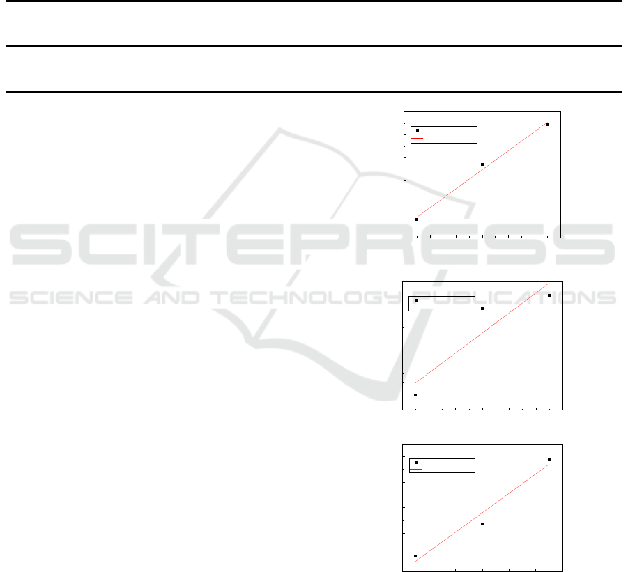
the large flue increases significantly. From Table 2,
it can be calculated that with a material layer
thickness of 550 mm, the SO
2
, NO and CO emission
rates are respectively 432.8, 111.8 and 9558.8 kg/h,
respectively. With the material layer thickness as
600 mm, the SO
2
, NO and CO emission rates are
456.9, 116.5 and 10189.2 kg/h, respectively. Finally,
with the material layer thickness as 650 mm, the
SO
2
, NO and CO emission rates are 474.4, 117.3 and
11457.3 kg/h. Figure 5(a)–(c) are the linear
relationship diagrams of SO
2
, NO and CO emissions
versus the material layer thickness, respectively. The
material layer thickness positively affects the
emission of the main pollutants of the flue
gas—linear correlation.
540 560 580 600 620 640 660
430
440
450
460
470
480
SO
2
emission amount (kg/h)
Material thickness
()
mm
(a)
y=0.415x+205.410
R
2
=0.9917
SO
2
Linear Fit of SO
2
540 560 580 600 620 640 660
111
112
113
114
115
116
117
118
NO emission amount (kg/h)
()
Material thickness mm
(b)
y=0.054x+82.513
R
2
=0.8480
NO
Linear Fit of NO
540 560 580 600 620 640 660
9500
10000
10500
11000
11500
CO emission amount (kg/h)
()
Material thickness mm
(c)
y=18.985x-989.234
R
2
=0.9637
CO
Linear Fit of CO
Figure 5: Linear relationship between pollutant emissions
and layer thickness.
ICBEB 2022 - The International Conference on Biomedical Engineering and Bioinformatics
452

3.1.5 Effect of Material Layer Thickness on
Pollutant Discharge
Table 3 shows the relevant parameters of sintering
machine products under different material layer
thickness conditions. As the material layer thickness
continuously increases, the sinter output and
utilisation factor of the sintering machine are
significantly improved. This trend occurs due to the
increment in the total batching amount after the
material layer thickness is increased. The drum index
has a small increase, which may be related to the
enhancement of the heat storage effect of the
sintering machine after the material layer thickness
of the sintering machine increases. Figure 5 shows
that as the material layer thickness increases, the
emissions of various pollutants also increase.
However, after converting the concentration of each
pollutant to the emissions per tonne of the sintered
ore, the thickness of the sintered material layer
increases, and the amount of SO
2
emissions
decreases from 1.79-kg/t to 1.57-kg/t-sintered ore.
Meanwhile, NO emissions decrease from 0.46-kg/t
to 0.39-kg/t-sintered ore, and CO emissions decrease
from 39.6-kg/t to 37.9-kg/t-sintered ore. As the
thickness of the sintered material layer increases, the
concentration of pollutants in the sintering flue gas
changes slightly. However, the emissions per tonne
values of the products are significantly reduced,
indicating that increasing the thickness of the
sintered material positively affects the sintered
material significantly, and the promotion effect also
positively affects the emission reduction of the
sintering flue gas pollutants (Qie 2019).
Table 3: Production of sintering machines with different layer thicknesses.
Material layer thickness (mm) Output per unit (t/h) Drum index (%)
Utilisation facto
r
(t/m
2
·h)
550 241.5 76.99 1.15
600 268.8 77.23 1.28
650 302.4 77.66 1.44
4 CONCLUSIONS
(1) The emission of SO
2
in the air box is low in the
middle and later stages of the sintering process, and
an obvious peak occurs in the middle and later
stages of sintering. Consequently, as the
over-humidity zone disappears, SO
2
is precipitated
again, and the emission increases rapidly. When the
combustion zone gradually disappears, the emission
concentration of SO
2
decreases rapidly.
(2) The CO emission characteristics are similar
to those of NO, in that the concentration of the
sintering machine head increases rapidly, the
emission concentration of the middle sintering stage
is stable, and the emission concentration of the
sintering machine tail decreases rapidly. Both are
directly related to the change in the combustion zone
during the fuel combustion process of the sintering
machine. As the initial combustion zone thickens
and its emission concentration increases rapidly, the
mid-term combustion zone tends to stabilise, and its
emission concentration is relatively stable. The later
combustion zone shrinks until it disappears, its
emission concentration decreases rapidly.
(3) SO
2
, NO and CO in the sintering flue gas
have a positive linear correlation with the material
layer thickness. The higher the material layer
thickness and the larger the batching amount, the
higher the emissions of pollutants in the sintering
flue gas. Comparing the production status of the
sintering machine under three material layer
thicknesses showed that the sintering machine has a
high utilisation factor and a large product output
under the high material layer thickness. The sinter
drum index is slightly increased, and the SO
2
, NO
and CO emissions can be reduced by 0.22-kg/t,
0.07-kg/t and 1.7-kg/t-sintered ore, which indicates
that the thick material layer sintering is more
conducive to improving the output and quality of
sintering, and has a positive effect on pollutant
emission reduction.
ACKNOWLEDGEMENTS
The present work is supported by the National Key
Research and Development Program of China
(No.2018YFC0213402), Major Science and
Technology Project of Inner Mongolia Autonomous
Region (No.2020ZD0013) and the Beijing
Municipal Commission of Science and Technology
(grant D171100007917001).
Study on Effect of Material Layer Thickness on Pollutant Emissions from Sintered Flue Gas
453

REFERENCES
Chen Wangsheng, Luo Jing, Qin Linbo, et al. Selective
autocatalytic reduction of NO from sintering flue gas
by the hot sintered ore in the presence of NH3[J].
Journal of Environmental Management, 2015, 164
(DEC.1): 146-150.
Chun Tiejun, Long Hongming, Di Zhanxi,et al.Novel
technology of reducing SO2 emission in the iron ore
sintering[J]. Process Safety & Environmental
Protection, 2017,105: 297-302.
Cheng Zhengming, Ning Wenxin, Pan Wen, et al.
Research and application of ultra-deepbed
homogeneous sintering technology[J].Sintering and
Pelletizing, 2019(4).
Fan Xiaohui,Yu Zhiyuan, Gan Min,et al. Appropriate
Technology Parameters of Iron Ore Sintering Process
with Flue Gas Recirculation[J].ISIJ International,
2014, 54(11):2541-2550.
Fan Xiaohui, Wong Guojing, Gan Min,et al.Establishment
of refined sintering flue gas recirculation patterns for
gas pollutant reduction and waste heat recycling[J].
Journal of Cleaner Production,2019.
Huang Jianping. Application effect of steam spraying
technology on sintering surface[J]. Ferro-Alloys,
2019(6):22-25.
Li Heping, Wu Shengli1, Han Jiayou. Application of
sintering flue gas cleaning technology with method
of“ozone oxidation and circulating fluidized bed”[J].
Sintering and Pelletizing,2018,43(06):6-11+23.
Liao Jiyong, He Guoqiang. Progress and development of
sintering technologies during the last five years[J].
Sintering and Pelletizing, 2018, 43(05):5-15+23.
Liu Chen. Research on Behavior of SO2/NOx/COx in the
Process of Flue Gas Circulation Sintering of Iron
Ores[D].Central South University, 2013.
Li Yuran,Yan Xiaomiao,Ye Meng,et al. Summary and
evaluation for the desulfurization technologies applied
in iron-steel sintering flue gas[J].Environmental
Engineering,2014, 32(11):82-87.
Long Hongming, Chen Xiaolong, Chun Tiejun,et al.Sulfur
balance calculation of new desulfurization technology
in the iron ore sintering process[J].Metallurgical
Research & Technology,2016,113(1):107.
Lu L, Ooi T C,Li X.Sintering emissions and their
mitigation technologies[J].Iron Ore,2015:551-579.
Min Gan, Fan Xiaohui, Lv Wei,et al.Fuel pre-granulation
for reducing NOx emissions from the iron ore
sintering process[J]. Powder Technology, 2016:
478-485.
Pei Yuandong, Liao Jiyong, Zhang Junjie, et al. Discussion
on CO emission reduction in iron ore fines sintering
process[J]. Sintering and Pelletizing, 2019, 44(01):
73-77.
Qie J M,Zhang C X,Guo Y H,et al. Reducing the Sintering
Flue Gas Pollutants Emissions Based on the
Accumulation Heat Effect in Iron Ore Sintering
Process[J].Transactions of the Indian Institute of
Metals,2019.
Taira Kenji. NOx emission profile determined by in-situ
gas monitoring of iron ore sintering during packed-bed
coke combustion[J]. Fuel,2019, 236(JAN.15):244-250.
Wang Suping, Bi Xuegong, Weng Deming. Study on a
New Technology of Flue Gas Desulfurization in
Sintering Process [J]. Advanced Materials Research,
2013, 726-731: 2284-2290.
Wang Shijie, Zhang Qi, Zhang Gu, et al. Effects of
sintering flue gas properties on simultaneous removal
of SO2 and NO by ammonia-Fe(II)EDTA
absorption[J]. Journal of the Energy Institute, 2017.
Williams A, Jones JM, Ma L, Pourkashanian M. Pollutants
from the combustion of solid biomass fuels. Prog
Energy Combust Sci 2012; 38:113–37.
Wang Jie,Zhong Wenqi. Simultaneous desulfurization and
denitrification of sintering flue gas via composite
absorbent[J].Journal of Environmental Sciences 96
(2020) 64–71.
Wang Feng,Zhang Jun, Qie Junmao,et al. Emission law
and analysis of flue gas in sinter wind boxes[J].Iron &
Steel,2019(6).
Wang Yaozu, Liu Zhengjian, Zhang Jianliang, et al. Study
of stand-support sintering to achieve high oxygen
potential in iron ore sintering to enhance productivity
and reduce CO content in exhaust gas[J]. Journal of
Cleaner Production,2019.
Xing Fangfang, Jiang Qi, Zhang Zhiya, et al.The analysis
of multi-pollutant collaborative control technologies of
sinter flue gas in iron and steel industry[J].
Environmental Engineering, 2014,32(004):75-78.
Yan Xiaomiao, Li Yuran, Zhu Tingyu,et al. Review of
Emission and Simultaneous Control of Multiple
Pollutants from Iron-steel Sintering Flue Gas
Yu Zhiyu, Fan Xiaohui, Gan Min,et al.NOx Reduction in
the Iron Ore Sintering Process with Flue Gas
Recirculation[J].JOM,2017, 69(9):1570-1574.
Zhu Tingyu, Liu Qing,Li Yuran,et al. Emission
Characteristics of Multiple Pollutants from Iron- steel
Sintering Flue Gas and Review of Control
Technologies [J].Science & Technology Review,
2014(33): 53-58.
Zhang Xiaohui,Feng Peng,Xu Jiarui,et al.Numerical
research on combining flue gas recirculation sintering
and fuel layered distribution sintering in the iron ore
sintering process[J].Energy,192(2019).
Zhou Hao,Zhou Mingxi, Liu Zihao,et al. Modeling NOx
emission of coke combustion in iron ore sintering
process and its experimental validation[J]. Fuel, 2016,
179(sep.1): 322-331.
Zhu Dewang, He Aoping, Pan Jian, et al. Rule of
Greenhouse Gas COx Emission in Iron Ore Sintering
Process[J]. Iron & Steel,2006(2).
ICBEB 2022 - The International Conference on Biomedical Engineering and Bioinformatics
454
