
Ultra Low Power RF Energy Harvesting System using a Super Capacitor
as an Energy Reservoir for an IoT Node
Florian Grante, Ghalid Abib, Muriel Muller and Nel Samama
Laboratoire Samovar, Institut Polytechnique de Paris, T
´
el
´
ecom SudParis, D
´
epartement Electronique et Physique (EPh), 19,
rue Marguerite Perey, 91120, Palaiseau, France
Keywords:
RF Electromagnetic Energy Harvesting, WiFi, Autonomous Sensor, Schottky Diode, RF/DC Rectifier, Boost,
Energy Budget Analysis, Green IoT, DC/DC Boost, Super Capacitor.
Abstract:
In this paper, we propose a 2.45 GHz RF energy harvesting system to power a battery free Internet of Things
(IoT) sensor node. The system operates from an RF signal with a power as low as -20 dBm and includes an
RF to DC converter, a storage super capacitor and a voltage DC/DC up-conversion. The system components
are sized to provide the required electric energy to operate the connected object. The tested connected object
includes an ARM microcontroller, an ultra low-power sensor (temperature, pressure and humidity) and a
Bluetooth Low Energy interface for a wireless transmission toward a terminal such as a smartphone or tablet.
It requires 200 µJ per transmission cycle, which must be provided by the proposed harvesting system. This
system is tested in an anechoic chamber and using a constant power RF signal to characterize the energy
recovery time needed for measuring and transmitting the sensor data. Promising results show that the system
is capable of sending data after 5 hours of RF energy harvesting from a source distant with one meter.
1 INTRODUCTION
Climate change issues are pushing us to innovate to
solve the question of our energy sources for the fu-
ture. How can we reduce our carbon footprint? How
can we produce electricity that is healthier for the en-
vironment? We also see steps to reduce our consump-
tion with the least possible impact on our lifestyles.
We then provide an optimization work of the energy
consumption of our industries. To achieve this, the
key element of the solution is the ever increasing feed-
back of information on all our systems.
This is where the Internet of Things (IoT) comes
into play. Today, the IoT represents billions of con-
nected objects and the number is still growing expo-
nentially. It has multiple uses such as Industry 4.0
with predictive maintenance, the development of con-
nected cities with smart grids to optimize the distri-
bution of electricity in the network or more simply,
the management of heating at home which represents
more than two thirds of energy consumption in Eu-
rope (Commission, 2020).
However, the multiplication of these connected
objects has the side effect of increasing the environ-
mental impact of digital technology. Indeed, these
billions of connected objects are generally powered
by batteries that need to be renewed every year on
average. While the carbon footprint of an AAA bat-
tery is 65 gCO2e (ADEME, 2019), the production of
batteries for the IoT sector could generate 0.01 % of
Greenhouse Gas (GHG) in 2025 and 0.02 % by 2030
(IEA, 2021).
A new filed of research is developing to find alter-
native energy sources for the IoT called energy har-
vesting.
The principle is to recover energy from our envi-
ronment, natural or not. We then have connected ob-
jects powered by solar energy with the development
of organic photovoltaic panels without rare-earth el-
ements (Wu et al., 2017); but also with mechani-
cal energy as proposed by the company ZF Electron-
ics (ZFE, 2022) allowing the installation of switch
connected lamps without batteries. We also find
other sources of energy in research such as thermo-
electric energy (Correa-Betanzo et al., 2019) work-
ing with Seebeck effect, vibratory energy (Balgu-
vhar and Bhalla, 2018) and the one that interests
us in this work, electromagnetic energy (Franciscatto
et al., 2013) and more specifically here the WiFi radio
waves.
The objective is to develop a system capable of
recovering and converting the surrounding RadioFre-
Grante, F., Abib, G., Muller, M. and Samama, N.
Ultra Low Power RF Energy Harvesting System using a Super Capacitor as an Energy Reservoir for an IoT Node.
DOI: 10.5220/0011143400003286
In Proceedings of the 19th International Conference on Wireless Networks and Mobile Systems (WINSYS 2022), pages 15-21
ISBN: 978-989-758-592-0; ISSN: 2184-948X
Copyright
c
2022 by SCITEPRESS – Science and Technology Publications, Lda. All rights reserved
15
quency (RF) WiFi signals into a direct current (DC)
capable of powering a sensor in a connected object.
The principle of radio energy harvesting has been de-
veloped in research for nearly twenty years now and
has seen several evolutions, especially on the type
of signals used. Indeed, we can see research papers
focused on TV signals (Parks et al., 2013) (Lacerna
et al., 2022) in the early 2010s, whose frequencies are
around a few hundred MHz to papers more on the In-
dustrial, Scientific and Medical (ISM) band at 2.45
GHz (Berg
`
es et al., 2015) and GSM at 900 MHz and
1800 MHz (Ho et al., 2016) with the massive develop-
ment of WiFi, 3G, 4G systems in the world in recent
years.
The RF energy harvesting discipline is also split
into two: remote power on the one hand with Ra-
dioFrequency Identification (RFID) and the Near
Field Communication (NFC) standards for short dis-
tances or over longer distances that can have uses in
particular in the medical (Jin et al., 2019) or appli-
cation like the one proposed by Archos at CES2022.
A system with a power station supplying energy to
bateryless sensors operating with the principle of
beam forming to optimize power transmission over
radio waves (Archos, 2021). On the other hand, we
have power supply by opportunistic harvesting of am-
bient signals and this is what interests us here. Can we
power a connected object by harvesting the surround-
ing WiFi signals in a building?
We can find several works dealing about this prin-
ciple (Kim et al., 2014) (Tran et al., 2017), especially
in the 2.45 GHz ISM band that interests us. They con-
cern the development of the RF/DC converter which
is more or less complex with its theoretical characteri-
zation. In this work, we wish to go further by propos-
ing a study of the complete ecosystem in which the
RF energy harvester is supposed to operate properly
in order to conclude about the feasibility of such a
system. We present in section 2 the development of
a harvester for 2.45 GHz WiFi signals which will be
integrated into our system presenter in section 3. Fi-
nally, the section 4 presents the measurement results
under laboratory conditions.
2 RECTIFIER
To convert a RF WiFi signal into DC voltage, it is
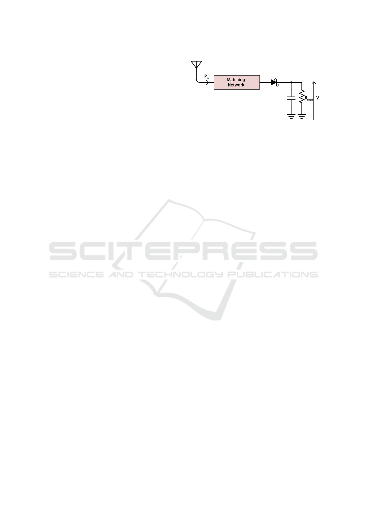
necessary to develop a Rectenna circuit following the
schematic represented in FIG.1, meaning the combi-
nation of an antenna and a rectifier circuit which will
convert the RF signal into DC voltage.
The received RF signal is converted into DC
thanks to a non-linear device based on a Schottky
Figure 1: A simple rectenna schematic.
diode. A matching network must be inserted between
the antenna and the diode for a maximal power trans-
fer. The diode is loaded by a low pass filter using a
capacitor and a resistor corresponding the equivalent
impedance of the connected object.
For the antenna part, we decided to use a classical
WiFi whip antenna as we can find it on routers, and
we focus on the development of the rectifier. Some
works on specific antenna can be found like (Srinivasu
et al., 2020), (Shen et al., 2018) or (Trinh et al., 2019).
We wish to work with ambient WiFi signals and
our different measurement campaigns of the available
power at a distance of 1 meter from the WiFi access
point led us to realize a system that must operate at an
incident power as low as -20 dBm.
For this reason, we restrict ourselves to a single-
wave rectifier composed of a single Schottky diode in
order to minimize the losses. We use the Skyworks
SMS7630 Schottky diode that is widely used in the
state of the art on rectennas for RF energy harvest-
ing (Trinh et al., 2019) (Kim et al., 2015). The cir-
cuit is optimized thanks to simulations performed on
Keysight Advanced Design System (ADS) software
and represented in FIG.2. The matching network is
synthesized thanks to microstrip transmission lines.
We used a 10 MΩ load resistance, which can be as-
similated to an infinite resistance in DC, because we
will use a capacitor to store the energy and whose
impedance tends to infinite in DC. The recovered out-
put DC voltage is about 178 mV for an input RF
power of -20 dBm at 2.45 GHz. Then, the optimized
rectifier circuit is realized (FIG.2) and characterized.
A measurement of |S
11
|, the input reflection coef-
ficient of the rectifier circuit, is shown in FIG.3 The
measured value below -8 dB at 2.45 GHz ensures
that our impedance matching network optimizes the
power transfer from the antenna to the diode.
As the goal is to recover a DC voltage at the recti-
fier’s output, we can characterize the performance of
the circuit by measuring this DC output voltage as a
function of the signal frequency, which can be seen in
FIG.3. We can note a maximum voltage of 159 mV
obtained for an incident signal of 2390 MHz at -20
WINSYS 2022 - 19th International Conference on Wireless Networks and Mobile Systems
16
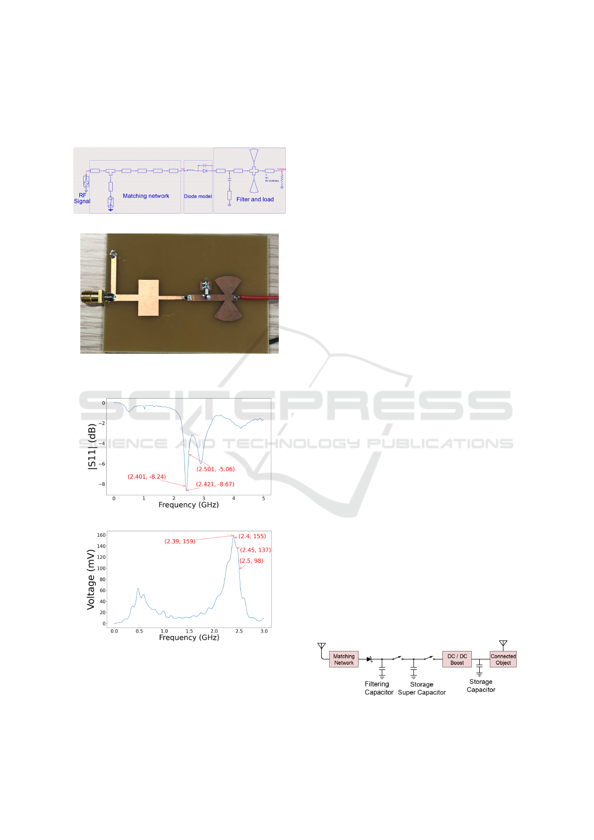
dBm, which is close to the 178 mV obtained through
simulation. According to FIG.3, we can expect an
output voltage between 98 mV and 155 mV over the
ISM band (2.4 GHz - 2.5 GHz).
(a) Rectifier schematic (Keysight ADS)
(b) PCB made in our laboratory
Figure 2: Schematic and PCB of the rectifier.
(a) |S
11
| measurement with an Anritsu MS46122B USB
VNA
(b) DC output voltage measurement Vs. input signal fre-
quency at -20 dBm
Figure 3: Rectifier characterization.
3 VOLTAGE BOOST
A DC voltage of 155 mV obtained in the ISM band is
insufficient to power a connected object whose supply
voltage is usually defined between 1.8 V and 3.3 V.
We must therefore use a voltage DC/DC boost to up-
convert the recovered low voltage.
The only voltage boost we know of that can op-
erate over such a low voltage range in the industry is
the LTC3108 from Analog Devices. Still, this voltage
boost is designed for a thermoelectric generator such
as a Peltier module, which has, in particular, a very
low impedance of few Ohms. If we connect this volt-
age boost directly to the rectifier output, it will lead to
an insufficient rectifier output voltage because of this
low impedance.
We have therefore imagined an intermediate sys-
tem between the rectifier and the voltage DC/DC
boost: a kind of energy reservoir that come and
go composed of a super capacitor surrounded by
switches. The complete system is shown in FIG.4.
The super capacitor reservoir is then sometimes
connected to the rectifier to recover the DC energy.
This capacitor being then the only load on the rectifier
and thus allow the best possible voltage by its infinite
DC impedance. And sometimes, it is connected to the
voltage DC/DC boost to discharge and thus, convert
the accumulated energy to a voltage level adapted to
our connected object. This boosted DC voltage will
be stored in the capacitor placed at the boost output.
This raises the question of the technology for the
switches. It is indeed essential to choose switches that
have the lowest possible leakage current and that can
toggle with a low voltage and current. As our key
value here is the voltage, we can eliminate the bipo-
lar transistors, which is controlled by a current whose
value cannot be controlled. MOSFETs on the other
hand can be considered because they are controlled in
voltage by the gate.
Another solution is the electromechanical relays.
Indeed, the switching is mechanical, so a real open
circuit is present and can be considered as no leakage
switches. The challenge is to find electromechanical
relays or MOSFETs without leakage that we can con-
trol with a voltage as low as 100 mV (Liu et al., 2014).
Voltage supervisors under 1 V exist and are used
in applications close to ours like the UB20M (UB2,
Figure 4: Schematic of our proposed circuit.
Ultra Low Power RF Energy Harvesting System using a Super Capacitor as an Energy Reservoir for an IoT Node
17
2017) which is able to detect a rectifier output volt-
age as low as 0.6 V. Even if it is still too high for our
system which must operate around 0.1 V, research pa-
pers seem promising on the subject, especially on the
side of electromechanical relays (Qian et al., 2017).
Even if they present constraints that do not allow to
use them as they are presented in the study, they al-
low to realize a switch activating at 100 mV with a
hysteresis up to 20 mV.
4 MEASUREMENTS AND TESTS
Now that we are able to rectify the RF WiFi signal
into a 3.3 V DC voltage, we would like to test the
whole system to see if it is able to power a connected
object to transmit data.
To ensure if our proposed design works, we will
use classical relays, which will be controlled and
powered by and additional circuit based on a micro-
controller, here an Arduino. The electric consumption
of these relays is not considered because they are not
supposed to be present in the final circuit. The com-
plete schematic of our system is represented FIG.5.
The circuit after the voltage DC/DC boost is a ca-
pacitor that stores the energy and a voltage supervisor
that is supposed to enable the Low DropOut (LDO)
regulator when the voltage is above the threshold of
2.63 V.
The connected object is made up of an ON-
Semi RSL10-SIP microcontroller based on an ARM
Cortex-M3 core and a Bluetooth Low Energy (BLE)
5.2 interface for a wireless transmission. It measures
temperature, pressure and humidity using an ultra-
low-power BME680 sensor from Bosch Sensortec. It
advertises a 25 bytes data frame following the pattern
on TAB.1 where UUID refers to a custom Universally
Unique IDentifier to identify which node is advertins-
ing the data. The energy need of this connected object
is around 200 µJ per transmission cycle. The details
of its energy consumption have been the subject of
work and a previous publication (Grante et al., 2020).
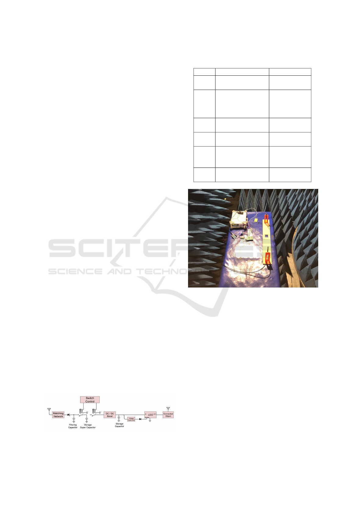
For a proper study and characterization and in or-
der to have control over the power of the RF sig-
nal source, a controlled environment is preferred.
Thus, we carried out our measurements in an anechoic
chamber (FIG.6) using a dedicated RF signal genera-
Figure 5: Schematic of our complete testing system.
Table 1: Sensor node data frame using BLE 5.2.
Byte Field Description
0 Frame Type
FLAGS for
the receiver
1-16 UUID[0]-[15]
Custom
128-bit
Service
UUID
17-18 TEMP[0]-[1]
Beacon
temperature
19-20 HUM[0]-[1]
Beacon
humidity
21-23 PRESSURE[0]-[2]
Beacon
atmospheric
pressure
24 VERSION
Service frame
version
Figure 6: Photo of the test setup inside the anechoic cham-
ber at Telecom Paris.
tor for transmission.
The output power of the RF generator is adjusted
so as to obtain an Effective Isotropic Radiated Power
(EIRP) of 20 dBm, which is the maximum emission
power allowed by the European legislation (ETSI,
2019) on this frequency range.
A few tests have shown that a 100 µF capacitor
loaded at 3.3 V ensure to give the 200 µJ necessary to
power the connected object to measure and transmit
its data. We were also able to determine that a su-
per capacitor of 2 F at 100 mV upstream of the volt-
age boost can achieve these conditions at the voltage
boost output in terms of voltage and amout of energy.
We followed the following protocol:
1. Connect a transmitting whip antenna (Tx) to an
RF signal generator and set the frequency to 2.45
GHz. The power is set to the maximum of what a
device in Europe can transmit, i.e., 20 dBm EIRP
WINSYS 2022 - 19th International Conference on Wireless Networks and Mobile Systems
18
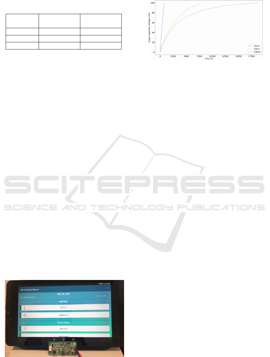
Table 2: Time needed to reach 100 mV across the super
capacitor.
Distance
(cm)
Time
(seconds)
Time
(HH:mm:ss)
25 786 00:13:06
50 7810 02:10:10
100 18716 05:11:56
2. The receiving whip antenna (Rx) is placed at 25
cm distant from the transmitter and is connected
to our rectifier system
3. Relays are setup to connect the super capacitor to
the rectifier to store energy
4. Monitoring the voltage using a voltmeter at the
terminals of the super capacitor as a function of
time until reaching 100 mV
5. When 100 mV is reached, the relays are switched
to isolate the rectifier and connect the super ca-
pacitor to the voltage DC/DC boost
6. The 100 µF capacitor is charged, its voltage rises
7. When 3.3 V are reached, the voltage supervisor
triggers the LDO regulator and allow discharging
the 100 µF capacitor in the connected object to
perform the measurement and transmit the data
through a BLE. The data are received and dis-
played by a smartphone application (FIG.7).
8. This procedure is repeated for a Tx/Rx distance of
50 cm and 100 cm.
We measured the evolution of the super capacitor
voltage as a function of time for the three distances.
We present the curves in the FIG.8 and the duration
to reach 100 mV in TAB.2. At 25 cm, a transmis-
sion is obtained after 786 seconds (13 minutes and 6
seconds). The curve has a linear appearance, which
can be explained by the proximity between the Tx
and Rx antennas. Indeed, the power received must
be greater than -20 dBm and thus makes it possible
to obtain a DC voltage at the rectifier’s output greater
Figure 7: The connected object that send data to the tablet
application.
Figure 8: Evolution of super capacitor voltage Vs.time us-
ing a 2450 MHz, 20 dBm EIRP emitter signal generator at
25, 50 and 100 cm.
than 100 mV and therefore, to reach this threshold
more quickly.
At 50 cm, we get 7810 seconds (2 hours, 10
minutes and 10 seconds). At constant efficiency,
since we have doubled the distance, the well known
Friis’ formula for free-space path loss (dependence
on the square of the distance) allows us to assume
that it should take 4 times longer to complete a
transmission. In practice, we observe that it takes
10 times longer. This can be explained by the
non-linearity of the diode which implies a decrease
in efficiency when the received powers are lower as
we have shown in the characterization of a rectifier
in (Grante et al., 2020). We can then approximate
that we have an average efficiency that is 10/4 = 2.5
times lower than if our system was linear.
At 100 cm, a transmission takes place after 18716
seconds (5 hours, 11 minutes and 56 seconds). Un-
like the measurement at 25 cm, here we see a curve
on FIG.8 that looks like the theoretical exponential
charge curve of a capacitor which leads us to think
that we have a rectifier output voltage close to the 100
mV threshold. We can then consider that it will be
difficult to go beyond a Tx/Rx distance of 100 cm be-
cause we would not have the 100 mV necessary at the
output of the rectifier.
5 CONCLUSION
We have proposed a rectifier capable of converting
WiFi signals into a DC voltage in the order of 150
mV for a received power of -20 dBm. We have used
the simplest possible rectifier using a single Schottky
diode because the state of the art on the subject leads
us to believe that it is not necessary to use more com-
plex configurations for incident powers as low as -20
dBm as indicated on TAB.3.
To allow a more relevant comparison with some
of the works in the table, a measurement of the output
Ultra Low Power RF Energy Harvesting System using a Super Capacitor as an Energy Reservoir for an IoT Node
19

Table 3: State of the art rectifier output voltage comparison.
Architecture
Number
of
Diodes
Load
(kΩ)
P
in
(dBm)
Frequency
(MHz)
V
out
(mV)
Ref.
Full rectifier 2 8.2 -20 890 114 (Ho et al., 2016)
Full rectifier 2 5 -20 2450 <200 (Selim et al., 2020)
Full rectifier 4 NA NA 2450 50 (Chen et al., 2017)
Single ended rectifier 1 Inf -20 2450 150 This work
Single ended rectifier 1 Inf -8 2450 542 This work
Dickson 4 NA -8 2450 500 (Fan et al., 2018)
Full rectifier 2 5 -8 2450 <500 (Selim et al., 2020)
voltage (V
out
) of our rectifier for an incident power
(P
in
) of -8 dBm has been performed.
This table shows some voltage values (V
out
) ob-
tained with different rectifier configurations. We
can see that our single-ended rectifier obtains simi-
lar performance in terms of voltage as more complex
schematics. This is due to the use of a super capaci-
tor as a load that allows us to consider an infinite load
and therefore to obtain a better voltage.
We could see that our system allowed us to trans-
mit data from a connected object, which is battery
free and powered thanks to an RF energy harvesting
at 2.45 GHz. The association of our rectifier with a
voltage DC/DC boost and storage capacitors is able
to supply a voltage of 3.3 V with enough energy to
allow the sensor data transmission. Whether at 25,
50 or even 100 cm Tx/Rx distance, we can expect at
least, 4 transmissions per day.
We can then imagine application cases such as
temperature monitoring in offices in order to optimize
the heating of the building and thus hope to save fossil
fuels.
However, currently, this has only been possible
with an external system that manages the switches al-
lowing passing to one side or the other of the system
without losing energy. In-depth study work is nec-
essary on these switches to have a fully autonomous
device.
It will also be necessary to test this system not
with a constant power RF signal generator but with
a WiFi signal to determine a minimum network activ-
ity to allow transmission in a reasonable time.
REFERENCES
(2017). UB20M High-Voltage, Low-Threshold, Ultra-Low
Power Voltage Detector for Energy Harvesting, RF
Power Transfer, and Event-Driven Sensing. Bristol
Energy. Rev 2.2.
ADEME (2019). Mod
´
elisation et
´
evaluation environ-
nementale de produits de consommation et biens
d’
´
equipement.
Archos (2021). Archos and ossia partner to bring inovative
wirelessly powered consumer iot products to market.
Balguvhar, S. and Bhalla, S. (2018). Green Energy Harvest-
ing Using Piezoelectric Materials from Bridge Vibra-
tions. In 2018 2nd International Conference on Green
Energy and Applications (ICGEA), pages 134–137.
Berg
`
es, R., Fadel, L., Oyhenart, L., Vigneras, V., and Taris,
T. (2015). A dual band 915MHz/2.44GHz RF energy
harvester. In 2015 European Microwave Conference
(EuMC), pages 307–310. ISSN: null.
Chen, X., Huang, L., Xing, J., Shi, Z., and Xie, Z.
(2017). Energy harvesting system and circuits for am-
bient WiFi energy harvesting. In 2017 12th Interna-
tional Conference on Computer Science and Educa-
tion (ICCSE), pages 769–772. ISSN: 2473-9464.
Commission, E. (2020). Heating and cooling.
Correa-Betanzo, C., Lopez-Perez, C., Rodriguez, A., and
Lopez-Nu
˜
nez, A. (2019). Isolated DC-DC Con-
verter for Thermoelectric Energy Harvesting Based
on a Piezoelectric Transformer. In 2019 IEEE Ap-
plied Power Electronics Conference and Exposition
(APEC), pages 3443–3447.
ETSI (2019). Etsi en 300 328 v2.2.2 (2019-07).
Fan, S., Zhao, Y., Gou, W., Song, C., Huang, Y., Zhou,
J., and Geng, L. (2018). A high-efficiency radio fre-
quency rectifier-booster regulator for ambient WLAN
energy harvesting applications. In 2018 IEEE MTT-S
International Wireless Symposium (IWS), pages 1–3.
Franciscatto, B. R., Freitas, V., Duchamp, J.-M., Defay, C.,
and Vuong, T. P. (2013). High-efficiency rectifier cir-
cuit at 2.45 GHz for low-input-power RF energy har-
vesting. In 2013 European Microwave Conference,
pages 507–510. ISSN: null.
Grante, F., Abib, G. I., Muller, M., and Samama, N. (2020).
Autonomous sensor node powered over WiFi. In WIN-
SYS 2020: 17th International Conference on Wireless
Networks and Mobile Systems, volume 1: WINSYS,
pages 127–132, Lieusaint, France. ScitePress.
Ho, D.-K., Kharrat, I., Ngo, V.-D., Vuong, T.-P., Nguyen,
Q.-C., and Le, M.-T. (2016). Dual-band rectenna for
ambient RF energy harvesting at GSM 900 MHz and
1800 MHz. In 2016 IEEE International Conference
on Sustainable Energy Technologies (ICSET), pages
306–310. ISSN: null.
WINSYS 2022 - 19th International Conference on Wireless Networks and Mobile Systems
20

IEA (2021). Iea (2021), global energy review 2021, iea,
paris.
Jin, Z., Hu, A., Liu, Z., and Liu, D. (2019). A 35µW Re-
ceiver Front-End with 35% wireless energy harvesting
efficiency for Wearable Medical Applications. In 2019
IEEE 13th International Conference on ASIC (ASI-
CON), pages 1–4. ISSN: 2162-755X.
Kim, J. H., Bito, J., and Tentzeris, M. M. (2015). Design
optimization of an energy harvesting RF-DC conver-
sion circuit operating at 2.45GHz. In 2015 IEEE In-
ternational Symposium on Antennas and Propagation
USNC/URSI National Radio Science Meeting, pages
1280–1281. ISSN: 1947-1491.
Kim, S., Vyas, R., Bito, J., Niotaki, K., Collado, A., Geor-
giadis, A., and Tentzeris, M. M. (2014). Ambient RF
Energy-Harvesting Technologies for Self-Sustainable
Standalone Wireless Sensor Platforms. Proceedings
of the IEEE, 102(11):1649–1666.
Lacerna, J. V. G., Guerra, E., and Jr, J. J. M. (2022). A
Heuristic Approach to Classifying Different Multi-
ple Urban Settings for Ambient RF Energy Harvest-
ing Potential using TV Technology as an RF Energy
Source. International Journal of Computing Sciences
Research, 6.
Liu, T.-J. K., Xu, N., Chen, I.-R., Qian, C., and Fujiki, J.
(2014). NEM relay design for compact, ultra-low-
power digital logic circuits. In 2014 IEEE Interna-
tional Electron Devices Meeting, pages 13.1.1–13.1.4.
ISSN: 2156-017X.
Parks, A. N., Sample, A. P., Zhao, Y., and Smith, J. R.
(2013). A wireless sensing platform utilizing ambi-
ent RF energy. In 2013 IEEE Topical Conference
on Biomedical Wireless Technologies, Networks, and
Sensing Systems, pages 154–156.
Qian, C., Peschot, A., Osoba, B., Ye, Z. A., and Liu, T.-
J. K. (2017). Sub-100 mV Computing With Electro-
Mechanical Relays. IEEE Transactions on Electron
Devices, 64(3):1323–1329. Conference Name: IEEE
Transactions on Electron Devices.
Selim, K. K., Wu, S., and Saleeb, D. A. (2020). An Op-
timized Rectifier Design for RF Energy Harvesting at
the 2.45 GHz WiFi Frequency Band. In 2020 27th In-
ternational Conference on Telecommunications (ICT),
pages 1–5.
Shen, S., Chiu, C.-Y., and Murch, R. D. (2018). Multi-
port Pixel Rectenna for Ambient RF Energy Harvest-
ing. IEEE Transactions on Antennas and Propaga-
tion, 66(2):644–656. Conference Name: IEEE Trans-
actions on Antennas and Propagation.
Srinivasu, G., Gayatri, T., Chaitanya, D., and Sharma, V.
(2020). Performance Analysis of a Compact High
Gain Antenna for RF Energy Harvesting in 1.71GHz
to 12GHz. In 2020 IEEE International RF and Mi-
crowave Conference (RFM), pages 1–4.
Tran, L.-G., Cha, H.-K., and Park, W.-T. (2017). RF
power harvesting: a review on designing methodolo-
gies and applications. Micro and Nano Systems Let-
ters, 5(1):14.
Trinh, L. H., Vu Ngoc Anh, H., Trinh, V. H., Duy Phan, D.,
Thi Khanh, H. N., and Ferrero, F. (2019). Design of a
Dual-band Rectenna for Small IoT Terminal. In 2019
International Symposium on Electrical and Electron-
ics Engineering (ISEE), pages 150–154.
Wu, T., Arefin, M. S., Redout
´
e, J., and Yuce, M. R. (2017).
Flexible wearable sensor nodes with solar energy har-
vesting. In 2017 39th Annual International Confer-
ence of the IEEE Engineering in Medicine and Biol-
ogy Society (EMBC), pages 3273–3276.
ZFE (2022). ZF Switches & Sensors - Switches, Sensors &
Wireless Technology.
Ultra Low Power RF Energy Harvesting System using a Super Capacitor as an Energy Reservoir for an IoT Node
21
