Robust Neural Network for Sim-to-Real Gap in End-to-End Autonomous
Driving
Stephan Pareigis
a
and Fynn Luca Maaß
b
Department of Computer Science, HAW Hamburg, Berliner Tor 7, 20099 Hamburg, Germany
Keywords:
Sim-to-Real Gap, End-to-End Learning, Autonomous Driving, Artificial Neural Network, CARLA
Simulator, Robust Control, PilotNet.
Abstract:
A neural network architecture for end-to-end autonomous driving is presented, which is robust against discrep-
ancies in system dynamics during the training process and in application. The proposed network architecture
presents a first step to alleviate the simulation to reality gap with respect to differences in system dynamics.
A vehicle is trained to drive inside a given lane in the CARLA simulator. The data is used to train NVIDIA’s
PilotNet. When an offset is given to the steering angle of the vehicle while the trained network is being ap-
plied, PilotNet will not keep the vehicle inside the lane as expected. A new architecture is proposed called
PilotNet∆, which is robust against steering angle offsets. Experiments in the simulator show that the vehicle
will stay in the lane, although the steering properties of the vehicle differ.
1 INTRODUCTION
The motivation for this particular research question
is based upon a laboratory experiment with minia-
ture autonomous vehicles (Tiedemann et al., 2019).
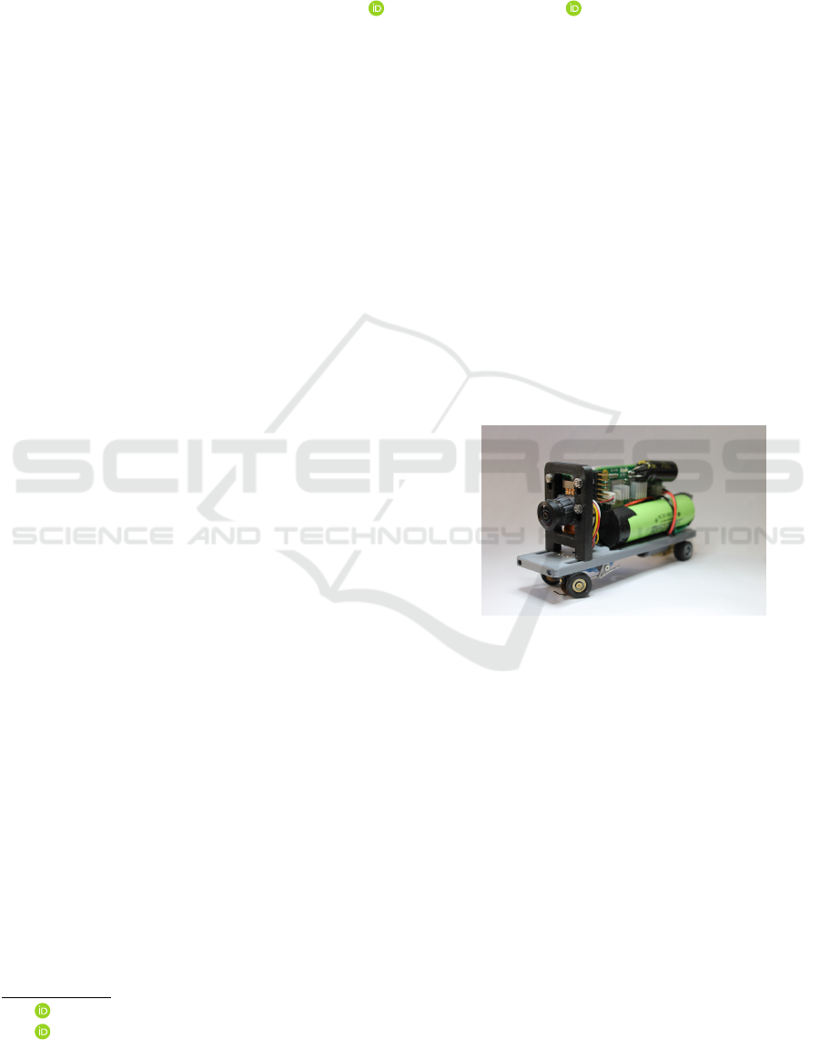
Vehicles in the scale 1 : 87 as shown in Figure 1
shall be constructed to drive autonomously in a model
city. The vehicles use a small camera and a mi-
croprocessor to do on-board image based feature ex-
traction of the environment. The microprocessor al-
lows a TPU (google coral) to be connected for faster
ML inference. The experimental setup provides for
different technological approaches to be applied, in-
vestigated, and tested: Up to date several regres-
sion networks have been applied, conventional lane
recognition, various kinds of semantic lane segmen-
tation, imitation learning and reinforcement learn-
ing approaches. Some of these approaches combine
both image interpretation and steering control, e.g.
reinforcement learning, and end-to-end approaches.
Other algorithms like lane segmentation require an
additional control method for steering to be applied
on top of the image recognition. In these latter cases,
usually pure pursuit methods are used for steering
control.
Many of the above mentioned approaches are very
sensitive to small deviations in the vehicle dynamics
a
https://orcid.org/0000-0002-7238-0976
b
https://orcid.org/0000-0002-4555-4870
Figure 1: Miniature Autonomous Vehicle. The steering me-
chanics are sensitive and difficult to adjust precisely. Con-
trol algorithms have to account for small deviations.
between training and inference. In the particular case
of very small model vehicles, the mechanical preci-
sion plays an important role in the success of a control
algorithm. Generally, in robotics, the availability of
methods which are robust against imprecise calibra-
tion is of advantage, as mechanical adjustments may
be subject to change during operation.
This leads to the question of a control method
which is robust against small deviations in system dy-
namics of the vehicle. As some of the above men-
tioned algorithms are trained using a simulation, the
problem setting can be regarded as a simulation to re-
ality gap problem. A simulation builds on a perfectly
calibrated system. The resulting algorithms will not
work when applied to a falsely calibrated system in
reality.
Pareigis, S. and Maaß, F.
Robust Neural Network for Sim-to-Real Gap in End-to-End Autonomous Driving.
DOI: 10.5220/0011140800003271
In Proceedings of the 19th International Conference on Informatics in Control, Automation and Robotics (ICINCO 2022), pages 113-119
ISBN: 978-989-758-585-2; ISSN: 2184-2809
Copyright
c
2022 by SCITEPRESS – Science and Technology Publications, Lda. All rights reserved
113
However, our interest is not only to overcome the
simulation to reality gap, but to find a general ap-
proach for robustness with regard to vehicle steering
mechanics. Of particular interest is an offset in the
steering angle. This means that with a value of 0 to the
steering servo, the vehicle will not drive in a straight
line but in a slight curve. This steering offset may
be very sensitive and may change when picking the
miniature vehicle up and putting it back down. The
offset of the steering angle may therefore practically
change during operation.
As mentioned above, different paradigms exist
for autonomous driving. (Chen et al., 2015) present
an overview: Mediated perception, direct perception,
and behaviour reflex. The end-to-end approach in this
experiment belongs to the behaviour reflex paradigm.
To approach this question, a simple simulation us-
ing the autonomous driving simulator CARLA (Doso-
vitskiy et al., 2017) was set up. An end-to-end
approach using NVIDIA’s PilotNet (Bojarski et al.,
2016) (Bojarski et al., 2017) was implemented and
trained. See (Bojarski et al., 2020) for current work
on PilotNet.
Training was performed using perfect system dy-
namics. The approach requires learning steering an-
gles in a supervised learning setting based on state in-
formation. When the trained neural network is being
applied (inference phase) to a vehicle with the same
perfect system dynamics as during the training pro-
cess, the vehicle behaves as desired and stays in the
lane.
When a steering angle offset is applied to the ve-
hicle system dynamics during the inference phase, the
vehicle will follow the road, however, it will drive
with an offset either closer to the right boundary line
of the lane, or closer or on top of the middle line, de-
pending on the angle offset.
The proposed network architecture PilotNet∆ cor-
rects angle offsets. The steering properties of
PilotNet∆ prove to be independent of mechanical
steering offsets. Experiments show that the proposed
correction method works for a wide range of offset
values. It can be seen in the experiments that the
impulse response of the vehicle with a steering off-
set slightly differs from the original impulse response
used during training.
The special idea of PilotNet∆ is that it takes three
consecutive images as an input and learns an angu-
lar difference, as opposed to the absolute angle as in
PilotNet. To process three input images, an LSTM
architecture is used in PilotNet∆. Other similar archi-
tectures have been proposed using LSTMs, e.g. (Er-
aqi et al., 2017), in which the focus is on detecting
temporal dependencies. Other extensions to PilotNet
have been made as e.g. in (Hecker et al., 2018) using
a 360° camera, or in (Codevilla et al., 2017) where
extensions to PilotNet on a feature level were made.
Also the problem of class imbalance, which oc-
curs in the proposed experimental setup, has been ad-
dressed by various authors, e.g. (Chawla et al., 2011)
who solve the problem using over/under sampling,
and (Ling and Sheng, 2010) who use cost sensitive
loss functions. The latter approach is used in the pro-
posed experiment.
Section 2 describes the experimental setup inside
the simulator CARLA. Section 3 introduces the pro-
posed neural network architecutre PilotNet∆ . Section
4 contains the experimental results and comparisons
between PilotNet and PilotNet∆ and section 5 con-
cludes the results.
2 EXPERIMENTAL SETUP
The experimental setup consists of a CARLA envi-
ronment (Dosovitskiy et al., 2017) to collect training
data. The data is used to train NVIDIA’s PilotNet (Bo-
jarski et al., 2016) and the here proposed PilotNet∆.
Two maps have been created inside CARLA using
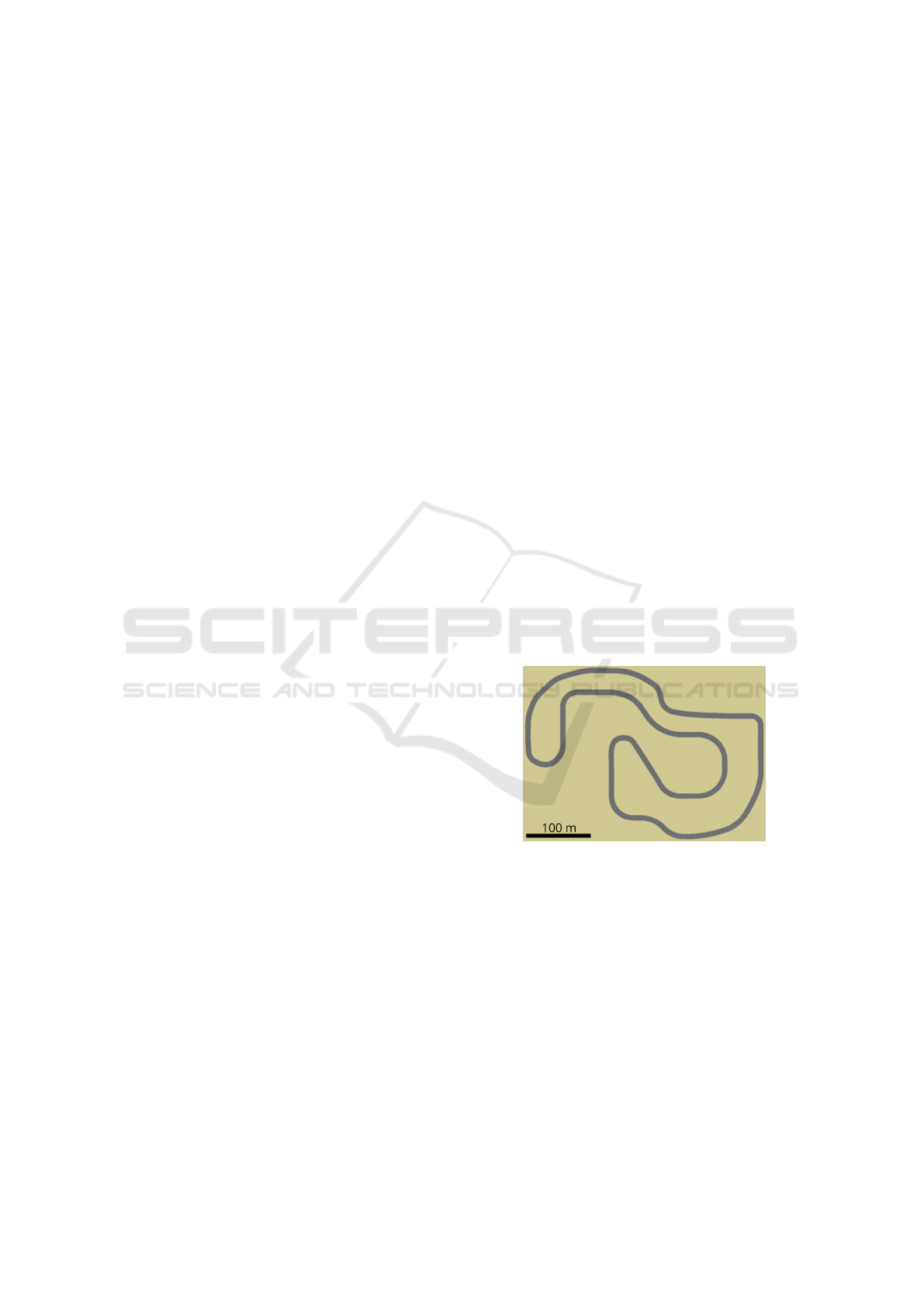
the RoadRunner tool (Mathworks, 2021). The map in
Figure 2 is used to collect training data. The map in
Figure 3 is used for testing.
Figure 2: Map for collecting training data. Curves with dif-
ferent curvature and length were created. A PID controller
provided by CARLA’s traffic manager keeps the vehicle in-
side the lane. Steering angles created in this way are used
to label images of the front facing camera as in Figure 4.
CARLA provides a tool called traffic manager
(CARLA, 2021). The traffic manager allows vehi-
cles to drive inside the simulation according to traf-
fic rules. The traffic manager uses a PID controller
to keep the vehicles inside their lanes. The traffic
manager is used in this experimental setup to steer the
vehicle and create training data. CARLA provides a
simulated image of a front facing camera inside the
vehicle. The environment in this experimental setup
is deliberately kept simple. The focus of the setup
ICINCO 2022 - 19th International Conference on Informatics in Control, Automation and Robotics
114
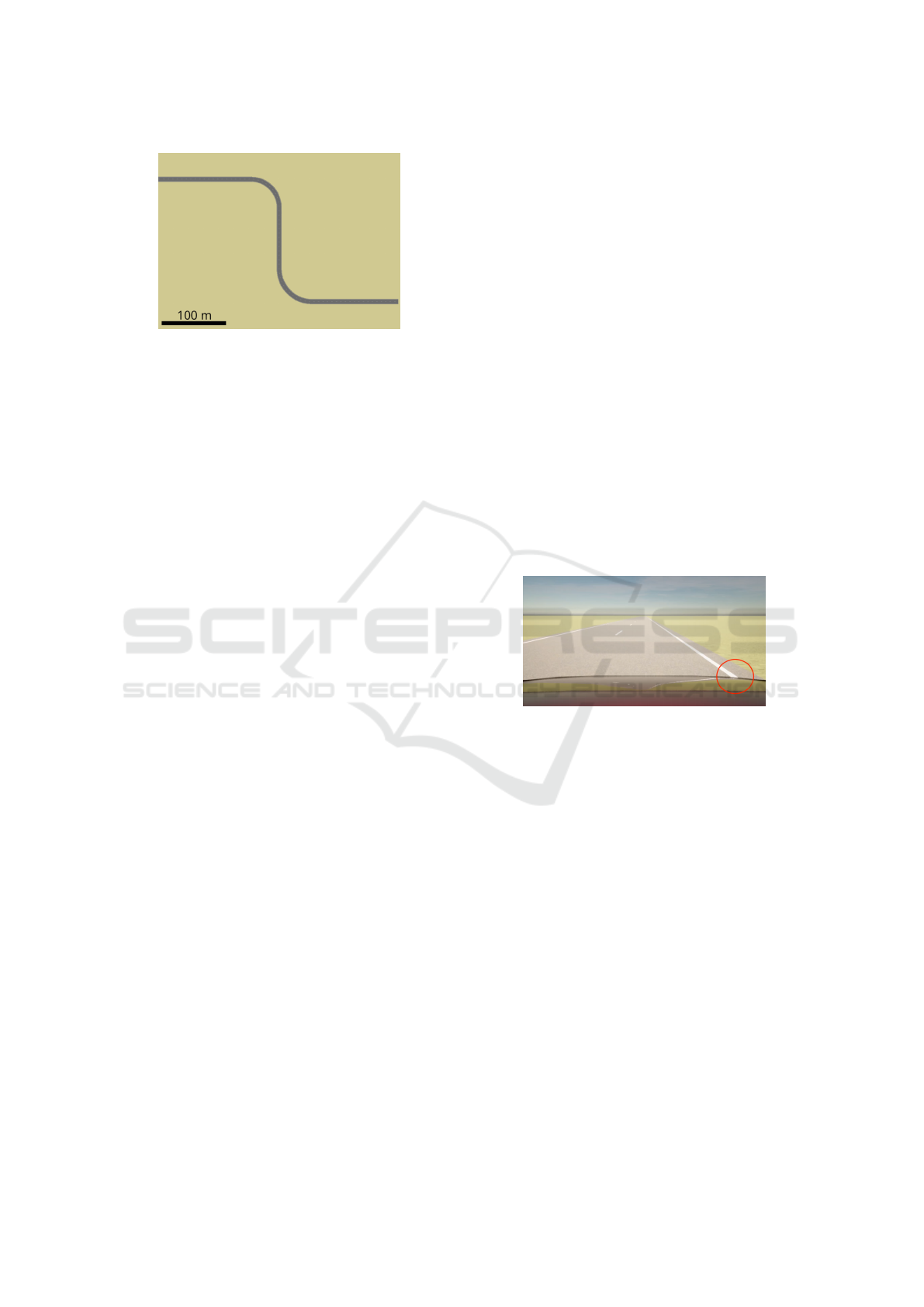
Figure 3: Map for testing the behaviour of the vehicle in a
right and left curve.
is to understand control theoretical behaviour of the
neural network. See Figure 4 for an example of the
images which have been produced by the simulation.
In addition to the images of the front facing cam-
era, CARLA also provides steering angles of the vehi-
cle, which have been calculated by the PID controller.
The images (as input to the neural network), together
with the corresponding steering angles (as labels), are
used as training data in this experimental setup.
2.1 Data Creation
Training data is generated using two principles. First,
the vehicle is driven on the map in Figure 2 using the
traffic manager. Images and steering angles are col-
lected. Figure 8 shows a distribution of the collected
steering angles in this setting. Second, the vehicle is
initially put on the lane with a lateral offset. The traf-
fic manager then guides the vehicle back to the correct
lateral position of the lane in an S-shaped curve. Also
in this case, images and corresponding steering an-
gles are collected. Figure 9 shows the distribution of
steering angles for this case.
It shall be mentioned that the images are cropped
above the horizon before being used as training data.
This allows a faster training process, as the input im-
ages are smaller. It also provides independence of the
outcome upon any kind of simulated clouds above the
horizon.
2.2 Evaluation Methods
Evaluation of NVIDIA’s PilotNet and PilotNet∆ is
done in the CARLA simulator in a driving test. The
vehicle is placed on the test map with the trained
model steering the vehicle. The position of the ve-
hicle throughout the map is compared to the ground
truth trajectory generated by the vehicle steered with
CARLA’s traffic manager. Given this, the error in lat-
eral position is calculated at any simulation time step.
Further, the mean absolute error in lateral position is
calculated. A mean absolute error in the lateral po-
sition of zero would mean that the vehicle’s trajec-
tory is identical to the ground truth trajectory of the
traffic manager, which is a best-case scenario. Pilot-
Net and PilotNet∆ are evaluated twice. First, with no
changes in system dynamics of the vehicle. Second,
with changes in system dynamics of the vehicle in the
form of a steering offset of -7.5 degree (left). In the
latter, if the model steers the vehicle straight ahead, it
constantly drives 7.5 degrees to the left.
2.3 Training and Results of PilotNet
The data, as described above, is used to train
NVIDIA’s PilotNet (Bojarski et al., 2020). As ex-
pected, the vehicle stays perfectly inside the lane, pro-
vided that the vehicle has the same steering properties
as during generation of the training data. Figure 4
shows an image of the front facing camera inside the
vehicle, when its lateral position is as desired. The red
circle indicates the position of the right lane boundary
with respect to the vehicle. This helps the viewer to
acknowledge the correct lateral position.
Figure 4: Front facing camera inside the CARLA simula-
tion. The environment is deliberately kept simple to focus
on control theoretical aspects of the setup. The red circle
helps the viewer to identify the lateral position of the vehi-
cle. This case shows the car with the desired lateral position
on the lane.
In the next experiment, an offset is added to the
steering angle. This shall simulate an incorrect zero-
adjustment of the steering mechanics. The experi-
ment shows that the vehicle coarsely follows the lane.
However, the lateral position of the vehicle is closer
or on top of the middle lane, leading to unacceptable
driving behavior. Figure 5 shows an image from in-
side the vehicle. In curves, the vehicle behaves errat-
ically and may also leave the lane.
3 PilotNet∆
A new end-to-end architecture called PilotNet∆ (Pi-
lotNet Delta) is proposed in this paper. The architec-
ture has increased robustness against different steer-
Robust Neural Network for Sim-to-Real Gap in End-to-End Autonomous Driving
115
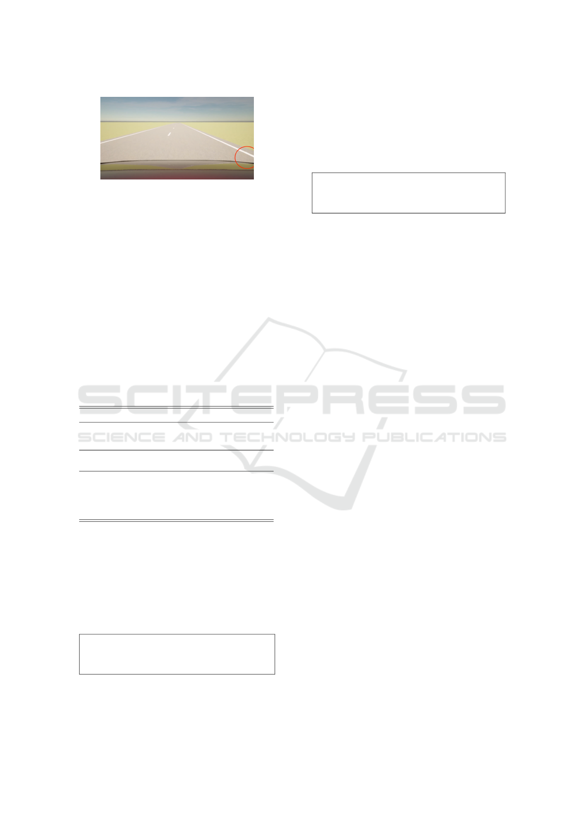
Figure 5: In this case, the vehicle is positioned to the left
of the desired lateral position. Looking at the red circle,
which indicates the position of the right lane boundary with
respect to the vehicle, helps to see this. See Figure 4 for
comparison. This is the behaviour which is received when
the vehicle has been trained with perfect steering mechan-
ics, and an offset is added to the steering angle during the
inference phase.
ing offsets, characterized by a lower mean absolute
error in positioning compared to the original PilotNet
driving under same conditions.
3.1 Neural Network Architecture
Table 1 illustrates the new CNN-LSTM architecture
of PilotNet∆.
Table 1: PilotNet∆ Architecture including a ConvLSTM
Layer - 315,291 Parameters.
Layer Type Stride Activation Output Shape Params
Input Sequence - - 3x66x200x3 -
Standardization - - 3x66x200x3 -
ConvLSTM2D 5x5 2x2 ELU 24@31x98 64896
Dropout 0.2 - - 24@31x98 -
Conv2D 5x5 2x2 ELU 36@14x47 21636
Conv2D 5x5 2x2 ELU 48@5x22 43248
Conv2D 3x3 1x1 ELU 64@3x20 27712
Dropout 0.2 - - 64@3x20 -
Conv2D 3x3 1x1 ELU 64@1x18 36928
Flatten - - 1152 -
Dropout 0.2 - - 1152 -
Dense - ELU 100 115300
Dense - ELU 50 5050
Dropout 0.2 - - 50 -
Dense - ELU 10 510
Output - - 1 11
315,291
The general structure of PilotNet∆ is very similar
to the original PilotNet from NVIDIA. PilotNet∆ in-
cludes one major difference in regard to the input and
output of the neural network. Originally, NVIDIA’s
PilotNet operates on single images at a time (image
t
)
labeled with the corresponding absolute steering an-
gle (α
t
), creating the mapping as depicted in Figure
6.
PilotNet Input → Output Behaviour
image
t
7→ α
t
Figure 6: PilotNet takes a single image as input and learns
the corresponding absolute steering angle α
t
.
PilotNet∆ follows a different approach. The archi-
tecture takes the last three frames at a time t: image
t
,
image
t−1
, image
t−2
, labeled with the amount the an-
gle (α
t
) has to change compared to the previous angle
(α
t−1
), referred to as relative angle, creating the fol-
lowing mapping:
PilotNet∆ Input → Output Behaviour
(image
t
, image
t−1
, image
t−2
) 7→ α
t
− α
t−1
Figure 7: PilotNet∆ takes three consecutive images as input
and learns the corresponding relative steering angle ∆α
t
=
α
t
− α
t−1
.
Compared to NVIDIA’s PilotNet, PilotNet∆ im-
plements a convolutional LSTM layer to process the
sequence of three images (for a similar approach us-
ing an LSTM layer see (Eraqi et al., 2017)). Each
sequence has a shape of 3 by 66 by 200 by 3 pix-
els (sequence x height x width x channels), encoded
in the YUV color space. Each image is spatially 0.5
m apart from the next one. Compared to the orig-
inal architecture from NVIDIA, the PilotNet∆ net-
work contains 4 dropout layers throughout the model.
Besides the first ConvLSTM Layer, the dropout lay-
ers in between, and the different output, PilotNet∆
matches NVIDIA’s PilotNet in regard to layer number
and shapes. Due to the additional ConvLSTM layer,
PilotNet∆ contains 315,000 parameters and therefore
roughly 65.000 more than NVIDIA’s PilotNet.
3.2 Training Details
PilotNet∆ is trained in a supervised manner given
roughly 12.000 images (20 minutes of driving se-
quences) collected by the two principles introduced
in section 2.
Figure 8 shows the distribution of data that was
gathered by the traffic manager driving on the map
in Figure 4. Figure 9 shows the distribution of data
gathered by the traffic manager driving with an initial
lateral offset. Both data sets have nearly the same size
and are combined during training.
NVIDIA’s PilotNet is trained using single images
image
t
and respective absolute steering angles α
t
as
shown in Figure 6. The training data for PilotNet∆ is
based on the same data set. However, three consec-
utive images and relative steering angles are used as
training data as shown in Figure 7.
The unfavorable data distributions complicates the
training for PilotNet∆ and requires further actions to
ensure a successful training. Cost-sensitive loss func-
tions are a way to deal with class imbalance problems
(Ling and Sheng, 2010). A prototype cost-sensitive
ICINCO 2022 - 19th International Conference on Informatics in Control, Automation and Robotics
116
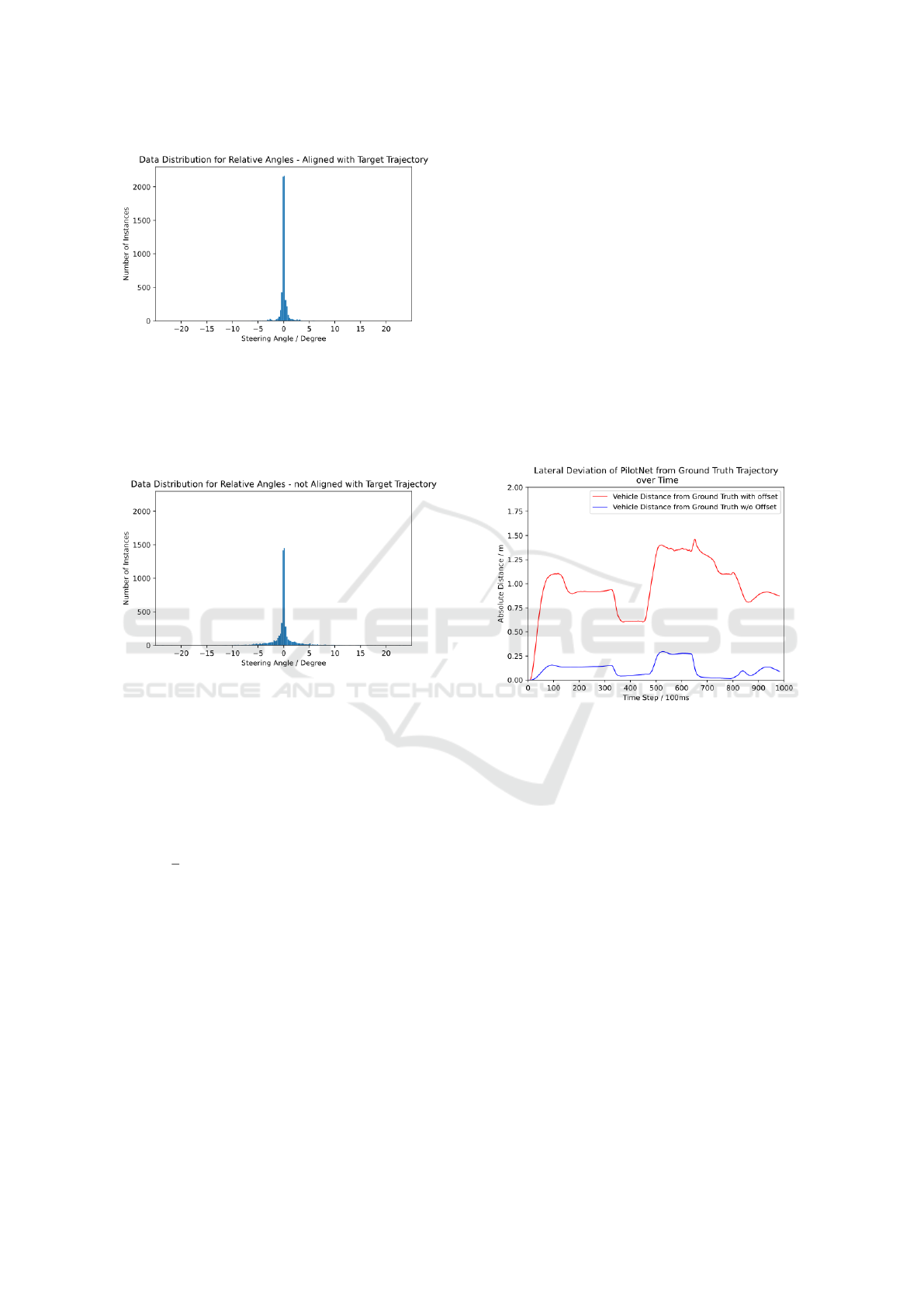
Figure 8: The diagram shows the distribution of gathered
data by the vehicle driving in the map in Figure 2 using
the traffic manager. The histogram with bins of 0.25 degree
width shows the distribution for relative angles while the
vehicle was driving inside its lane. 6,054 Images - Mean:
-0.0001 - Standard Deviation: 0.84. Most of the collected
relative steering angels are small, i.e. close to zero.
Figure 9: The diagram shows the distribution of gathered
data by the vehicle when it is initially put on the lane with
a lateral displacement. The histogram with bins of 0.25 de-
gree width shows the distribution for relative angles. 5,920
Images - Mean: 0.0004 - Standard Deviation: 04.16. It can
be seen that more data from curves has been collected in
this case. The peak at 0 is smaller (less data) and more data
from nonzero relative angles is available for training.
variation of the MSE loss function is proposed:
1
n
n
∑
t=1
(Y
pred
−Y
true
)
2
∗ (|Y
true
| + 0.1) (1)
It calculates the Mean Squared Error between the
model’s prediction (Y
pred
) to the ground truth steer-
ing angle (Y
true
). It then re-weights the MSE depend-
ing on the probability of the ground truth in the data
set. This loss functions benefits from the fact that the
amount of the ground truth correlates to its probabil-
ity. Ground truths with the value 0 are re-weighted
with a factor of 0.1. In contrast to over/under sam-
pling techniques (Chawla et al., 2011) that were tried,
the proposed cost-sensitive loss function in combina-
tion with a batch size of 200 leads to a good training
result.
4 EXPERIMENTAL RESULTS
For the following results, NVIDIA’s PilotNet and
PilotNet∆ drove on the test map in Figure 3 with
and without changed steering mechanics in the form
of a steering offset of -7.5 degrees (left). The fol-
lowing figures 10 and 11 illustrate the absolute error
in position from the ground truth trajectory given by
CARLA’s traffic manager over time.
4.1 Results for NVIDIA’s PilotNet
As mentioned previously, NVIDIA’s PilotNet perfor-
mance when driving without a change in steering me-
chanics was good. However, when an offset in the
steering is present, the driving performances was un-
acceptable.
Figure 10: Error in lateral position over time (red - driv-
ing with offset, blue - driving without offset) for PilotNet
when driving on the test map in Figure 3. The right curve is
approximately at [350, 480], the left curve at [650, 800].
Figure 10 illustrates the two different scenarios.
The blue function describes the lateral deviation from
the ground truth trajectory (i.e. CARLA’s traffic man-
ager) when NVIDIA’s PilotNet drove with no changes
in the steering mechanics. The right curve is be-
tween time steps [350, 480], the left curve between
[650, 800]. PilotNet shows the largest lateral displace-
ment of 25cm after the right curve. During the left
and during the right curve the lateral displacement is
minimal.
The red function shows the lateral deviation from
the ground truth trajectory when NVIDIA’s PilotNet
drove with a steering offset. The lateral deviation
is significantly higher throughout the whole test run.
The vehicle was pushed to the left side, driving close
or on the center mark of the lane, but managed to drive
successfully until the end.
Robust Neural Network for Sim-to-Real Gap in End-to-End Autonomous Driving
117
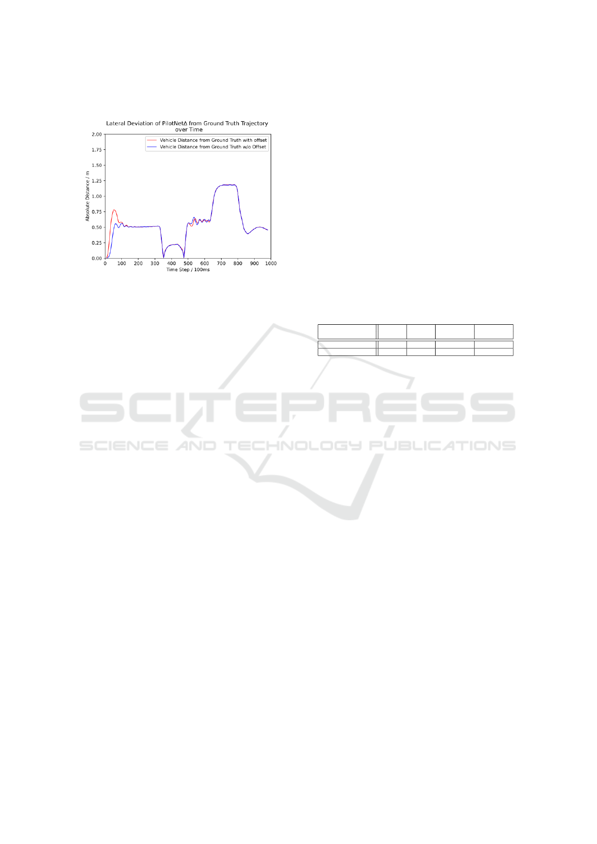
4.2 Results for PilotNet∆
Figure 11: The functions show the lateral deviation of the
PilotNet∆-driven vehicle with respect to the trajectory of
CARLA’s traffic manager over time (red - driving with off-
set, blue - driving without offset) on the test map. Apart
from the overshoot in the beginning, PilotNet∆ shows al-
most identical driving behaviour without and with a me-
chanical steering offset.
Figure 11 shows the error in positioning from the
ground truth trajectory of PilotNet∆ while driving
with changed system dynamics (red) compared to
driving without changed system dynamics (blue). In
contrast to NVIDIA’s PilotNet, both test runs for
PilotNet∆ show nearly identical results. This il-
lustrates the advantage of PilotNet∆ over NVIDIA’s
PilotNet and its abilities to compensate mechanical
steering offsets. When the vehicle drove with an off-
set in the steering (red), a difference in the start up
phase can be seen. Due to the offset, the vehicle de-
viated 0.75 m from the center of its lane for the first
100 time steps. After time step 100, both test runs are
identical.
The error in lateral position in the test run when
the vehicle drove without changed system dynamics
(blue) is larger than with PilotNet. It is seen, that
there is a measurable error in lateral position of about
0.5 m in the first segment of the test map. When the
vehicle was entering the first right turn at time step
300, the lateral displacement fell from 0.55 m to 0 m
and then rose again to 0.2 m. At this point, the ve-
hicle transitioned from the left side to the right side
relative to the ground truth trajectory. When the ve-
hicle entered the left curve at time step 480 the same
happened once again, but vice versa. On the second
straight road segment between time step 500 and 650
the error in positioning was about 0.6 m with small
oscillations present. In the left curve at time step 650
to 850 the vehicle deviated 1.2 m from the center of
its lane.
Table 2 concludes information already present in
the Figures 10 and 11 in a compact form. It shows the
mean absolute error in positioning across the whole
test runs and the maximum errors in positioning for
PilotNet and PilotNet∆ either with or without changed
system dynamics. The table concludes, that the base-
line performance of NVIDIA’s PilotNet is better than
the baseline performance of PilotNet∆ in regard to the
lateral positioning. However, the table clearly shows
once again the robustness of PilotNet∆ against chang-
ing system dynamics in the form of a steering off-
set. In a direct comparison from NVIDIA’s Pilot-
Net to PilotNet∆, both driving with a steering offset,
PilotNet∆’s mean absolute error in positioning is with
0.57 m significantly lower than NVIDIA’s PilotNet
with 0.98 m.
Table 2: MAE of PilotNet and PilotNet∆ during the eval-
uation process, driving with and without an offset, contra-
dicted.
Architecture MAE Max MAE with Max Error
Error with Offset with Offset
NVIDIA’s PilotNet 0.11 m 0.29 m 0.98 m 1.46 m
PilotNet∆ 0.55 m 1.18 m 0.57 m 1.19 m
5 DISCUSSION AND
CONCLUSION
It can be shown that the proposed neural network ar-
chitecture PilotNet∆ has the capability of compen-
sating deviations in steering mechanics. The exper-
iments are focused on an offset in the steering angle.
Other deviations in the steering mechanics, like vari-
ations in the conversion function from servo settings
to steering angle, have not yet been experimentally
investigated. Also, experiments with the real model
vehicle are pending.
PilotNet∆’s steering capabilities with respect to
the absolute derivation from the given path is inferior
to PilotNet. In our opinion, the proposed architecture
must be developed further to achieve the same accu-
racy as PilotNet.
The feature complexity of the simulation environ-
ment is intentionally reduced to a minimum for the
purpose of this paper. Generally, End-to-End solu-
tions are capable of learning complex image features,
capable of driving in the real world, including diffi-
cult scenarios such as parking lots and on unpaved
roads (Bojarski et al., 2016), (Wang. et al., 2019),
(Hoveidar-Sefid. and Jenkin., 2018).
There were major difficulties in preparing the data
to achieve robust training in the case of PilotNet∆.
When collecting data in an imitation learning setting,
too little information is collected to describe the be-
ICINCO 2022 - 19th International Conference on Informatics in Control, Automation and Robotics
118

haviour in curves, especially when relative steering
angles instead of absolute steering angles are used.
This is due to the fact that the vehicle mostly drives
with small steering angles. This results in the be-
haviour of the desired controller not being represented
adequately by the samples.
The use of a simulation offers great possibilities
for collecting sufficient data in the whole working
range of the controller. In the described setup, a PID-
controller was provided inside the simulation, which
was used as a role model from which the samples
have been taken. It may be asked if an existing PID-
controller is really necessary to train a neural network
to achieve a controller with a desired behaviour. Other
than a desired behaviour of the steering controller, a
cost function may be provided to be minimized and
reinforcement learning techniques can be applied. In
either case, the question of an exact formulation of
the requirements for vehicle steering and its control
properties has to be answered.
REFERENCES
Bojarski, M., Chen, C., Daw, J., De
˘
girmenci, A., Deri, J.,
Firner, B., Flepp, B., Gogri, S., Hong, J., Jackel, L.,
Jia, Z., Lee, B., Liu, B., Liu, F., Muller, U., Payne, S.,
Prasad, N. K. N., Provodin, A., Roach, J., Rvachov,
T., Tadimeti, N., van Engelen, J., Wen, H., Yang, E.,
and Yang, Z. (2020). The nvidia pilotnet experiments.
Bojarski, M., Del Testa, D., Dworakowski, D., Firner, B.,
Flepp, B., Goyal, P., Jackel, L. D., Monfort, M.,
Muller, U., Zhang, J., Zhang, X., Zhao, J., and Zieba,
K. (2016). End to End Learning for Self-Driving Cars.
arXiv e-prints, page arXiv:1604.07316.
Bojarski, M., Yeres, P., Choromanska, A., Choromanski,
K., Firner, B., Jackel, L., and Muller, U. (2017). Ex-
plaining How a Deep Neural Network Trained with
End-to-End Learning Steers a Car. arXiv e-prints,
page arXiv:1704.07911.
CARLA (2021). trafficmanager. //carla.readthedocs.io/
en/latest/adv traffic manager. Accessed: 2021-10-03.
Chawla, N. V., Bowyer, K. W., Hall, L. O., and
Kegelmeyer, W. P. (2011). SMOTE: Synthetic Mi-
nority Over-sampling Technique. arXiv e-prints, page
arXiv:1106.1813.
Chen, C., Seff, A., Kornhauser, A., and Xiao, J. (2015).
Deepdriving: Learning affordance for direct percep-
tion in autonomous driving. In 2015 IEEE Interna-
tional Conference on Computer Vision (ICCV), pages
2722–2730.
Codevilla, F., M
¨
uller, M., L
´
opez, A., Koltun, V., and Doso-
vitskiy, A. (2017). End-to-end Driving via Con-
ditional Imitation Learning. arXiv e-prints, page
arXiv:1710.02410.
Dosovitskiy, A., Ros, G., Codevilla, F., Lopez, A., and
Koltun, V. (2017). Carla: An open urban driving sim-
ulator.
Eraqi, H. M., Moustafa, M. N., and Honer, J. (2017). End-
to-End Deep Learning for Steering Autonomous Ve-
hicles Considering Temporal Dependencies. arXiv e-
prints, page arXiv:1710.03804.
Hecker, S., Dai, D., and Van Gool, L. (2018). End-to-
End Learning of Driving Models with Surround-View
Cameras and Route Planners. arXiv e-prints, page
arXiv:1803.10158.
Hoveidar-Sefid., M. and Jenkin., M. (2018). Autonomous
trail following using a pre-trained deep neural net-
work. In Proceedings of the 15th International Con-
ference on Informatics in Control, Automation and
Robotics - Volume 1: ICINCO,, pages 103–110. IN-
STICC, SciTePress.
Ling, C. and Sheng, V. (2010). Cost-sensitive learning and
the class imbalance problem. Encyclopedia of Ma-
chine Learning.
Mathworks (2021). Roadrunner. //de.mathworks.com/pro
ducts/roadrunner.html. Accessed: 2021-10-03.
Tiedemann, T., Fuhrmann, J., Paulsen, S., Schnirpel, T.,
Sch
¨
onherr, N., Buth, B., and Pareigis, S. (2019).
Miniature autonomy as one important testing means in
the development of machine learning methods for au-
tonomous driving : How ml-based autonomous driv-
ing could be realized on a 1:87 scale. In Interna-
tional Conference on Informatics in Control, Automa-
tion and Robotics 2019, ICINCO 2019 : proceedings
of the 16th International Conference on Informatics in
Control, Automation and Robotics, pages 483–488.
Wang., Y., Liu., D., Jeon., H., Chu., Z., and Matson.,
E. (2019). End-to-end learning approach for au-
tonomous driving: A convolutional neural network
model. In Proceedings of the 11th International Con-
ference on Agents and Artificial Intelligence - Volume
2: ICAART,, pages 833–839. INSTICC, SciTePress.
Robust Neural Network for Sim-to-Real Gap in End-to-End Autonomous Driving
119
