
Increasing the Autonomy of the Unmanned Aerial Platform
Wojciech Stecz
1 a
and Marcin Chodnicki
2 b
1
Faculty of Cybernetics, Military University of Technology, Warsaw, Poland
2
Air Force Institute of Technology, Warsaw, Poland
Keywords:
UAV, Autonomy, SysML, State Machine, Hardware-in-the-Loop.
Abstract:
The article presents the principles of designing a reliable architecture supporting Unmanned Aerial Vehi-
cle (UAV) control, taking into account the need to handle hazardous situations occurring during the flight.
Detailed attention was paid to the description of the UAV architecture components that affect the ability to
perform autonomous missions, understood as a flight without contact with the Ground Control Station (GCS).
The method of designing UAV flight algorithms in the conditions of occurrence of gusts of wind was pre-
sented. The principles of modeling the behavior of UAVs in situations of a potential air collision with another
platform or a collision with a terrain obstacle are described. Principles of modeling the hierarchy of handling
hazardous situations are presented. The developed models were tested on a computer architecture based on
ARM processors using the Hardware-in-the-Loop (HIL) technique. The presented solution uses a system of
UAV control computers in the form of a Flight Control Computer (FCC) based on a real-time operating system
(RTOS), and a Mission Computer (MC) based on a Linux system integrated with a Robot Operating System
(ROS). A method of integrating tasks related to the management of mission implementation with the algo-
rithms ensuring flight safety of the air platform is presented. The research was carried out on the basis of the
UAV mathematical model, stabilization and navigation algorithms and the Dryden turbulence model.
1 INTRODUCTION
Descriptions of the architecture of modern unmanned
aerial platforms are a frequently discussed topic in
scientific research in the field of unmanned aerial plat-
forms. A good example would be work (Sanchez-
Lopez et al., 2016). The designers of such systems
agree that each unmanned platform that can operate
autonomously, i.e. safe flight without contact with
GCS, must be equipped with the following comput-
ers: FCC (Flight Control Computer) and MC (Mis-
sion Computer) (Pastor et al). FCC, depending on
the size of the UAV in which they are used, can be
advanced control systems containing, in addition to
PID-based flight controllers, sensors such as GPS /
INS or ADC (Air Data Computer). The main task
of the FCC is to perform the role of an autopilot that
controls the flight between successive points. MC is
a unit that supervises the order of completing tasks
specified in a given mission. Both of these devices
cooperate with each other during the flight of the plat-
form. Depending on the advancement of the algo-
a
https://orcid.org/0000-0002-5353-5362
b
https://orcid.org/0000-0003-1348-289X
rithms implemented on these copunter, the UAV may
have the capability of autonomous flight. The article
assumes that the UAV can operate autonomously if it
can fly safely for other air platforms in the event of a
loss of communication with GCS. We ignore the le-
gal aspects of autonomous flights due to the breadth
of the topic.
In this article, we focus on tasks related to the im-
plementation of the reconnaissance mission of the un-
manned platform, which is equipped with an EO / IR
head and a SAR radar. We present a method of mod-
eling the behavior of UAVs in SysML, which takes
into account the implementation of the mission in the
conditions of loss of communication with GCS. In
this case, the air platform must operate autonomously.
This means that the MC and FCC computers should
have built-in algorithms for handling the implementa-
tion of subsequent tasks planned for the mission, han-
dling tasks in the event of adverse weather conditions
and flight control in the event of hazardous situations.
At this point, it is worth focusing on the types of al-
gorithms mentioned above.
In the case of the first group of algorithms, which
includes activities related to reconnaissance tasks
Stecz, W. and Chodnicki, M.
Increasing the Autonomy of the Unmanned Aerial Platform.
DOI: 10.5220/0011140100003266
In Proceedings of the 17th International Conference on Software Technologies (ICSOFT 2022), pages 365-373
ISBN: 978-989-758-588-3; ISSN: 2184-2833
Copyright
c
2022 by SCITEPRESS – Science and Technology Publications, Lda. All rights reserved
365

planned in the mission, the MC of the air platform
is designed to monitor the position of the UAV and, in
certain waypoints, turn on and off the reconnaissance
sensors. MC additionally configures individual sen-
sors, as described in (Stecz and Gromada, 2020). In
this article, we do not broadly describe the operation
of the air platform in the event of loss of contact with
the GCS, when tasks can be performed on a scheduled
basis and weather conditions do not affect the flight.
It is much more complicated to carry out a re-
connaissance mission in conditions of high wind
speed, and even more so with periodic gusts. Un-
der these conditions, the UAV must have implemented
algorithms belonging to the second group mentioned
above, periodically changing the operation of flight
regulators, as shown in the Section 3. For example,
when it is necessary to recognize an object using the
SAR radar, which requires high stability of the UAV
flight, in the reconnaissance section, the FCC com-
puter, due to the MC request, restricts the operation
of the tilt regulator. This is based on the assumption
that the UAV does not fly exactly along the route, but
is acceptable for this type of task.
The third group of algorithms are those securing
the platform’s flight and ensuring the safety of the
UAV in the air. These algorithms include algorithms
for avoiding collisions with terrain obstacles, algo-
rithms for avoiding collisions with other air platforms
and algorithms for preventing UAVs from flying out-
side the permitted zone. Some of them are described
in (Stecz and Gromada, 2022). In practice, there are
many more such algorithms and they can be catego-
rized according to the hierarchy of importance of the
situations they describe. The highest category situa-
tions include the sudden loss of UAV flight altitude
when communication, spatial and usually geographic
orientation is lost. In this case, the UAV mission com-
puter must immediately start the rescue procedure.
Usually it triggers an emergency procedure which, for
smaller platforms, means the parachute will be thrown
out. Lower priority situations were previously men-
tioned and are associated with potential collisions.
The lowest priority situations are those that do not af-
fect flight safety, but potentially delay the implemen-
tation of the mission plan.
The rest of the article is as follows. The Section 2
describes examples and important publications from
the area presented in the article. The Section 3 shows
the method of modeling selected procedures imple-
mented on the air platform in SysML in accordance
with the basic assumptions of MBSE. In particular,
the focus was on describing two types of implemented
functions: modifying the operation of PID regulators
during the flight and verifying possible collisions with
terrain and other air platforms. The Section 4 presents
exemplary results of regulators controlled by MC al-
gorithms. The Section 5 summarizes our achieve-
ments and indicates possible further directions for the
development of algorithms enhancing the autonomy
of UAV flight.
2 RELATED WORKS
The articles (Sanchez-Lopez et al., 2016), (Boubeta-
Puig et al., 2018) present the general structure of
the unmanned autonomous system, which allows for
making decisions about changing the trajectory by
UAV control computers in the absence of GCS con-
trol. The system consists of several modules respon-
sible for the implementation of the mission plan in an
autonomous mode.
Another example of UAV architecture is presented
in (Ilarslan et al., 2011). In this approach, the MC
computer acts as the main control system, therefore it
is based on the RTOS real-time system, and the FCC
autopilot is a slave system.
The FCC must be equipped, as previously men-
tioned, with a state machine with built-in special and
emergency logic, thanks to which it is able to indepen-
dently determine if the MC is malfunctioning. There-
fore, the MCs of smaller platforms are developed on
the Robot Operating System software. ROS is widely
used in robotics, it allows you to divide the entire
system into individual nodes, thanks to which adding
new functionalities is much easier. MC equipped with
software to supervise the correct implementation of
the mission, taking into account the operation of the
payload, supports the FCC. This configuration allows
better use of the UAV’s capabilities. Examples of de-
scriptions of special situations in the form of state ma-
chines implemented on the MC of the air platform can
be found in the works (Wang et al., 2019), (Stecz and
Gromada, 2022), (Stecz and Kowaleczko, 2021).
It is worth noting that when the platform uses the
MC computer, which acts as a computing unit, e.g.
for avoiding obstacles or modifying the flight route,
in this case the ROS system is used. In (Carvalho
et al., 2017) the open-source PX4 autopilot - FCC was
combined with a computer based on Linux and ROS.
Additionally, ROS is often used to prototype mission
planning algorithms and test them in a 3D virtual en-
vironment (Zhang et al., 2015). The FCC is responsi-
ble for the basic functions of stabilization and control
and is able to work independently of the supporting
MC. The communication between the FCC and MC
usually takes place via network interfaces to which
other sensors are also connected. This connection al-
ICSOFT 2022 - 17th International Conference on Software Technologies
366
lows direct access to both FCC and MC data.
The integration of FCC and MC may involve the
exchange of information aimed at modifying the con-
trols of the FCC regulators. The MC may send the
FCC a revision of the mission plan in a situation
where the analyzes conducted in the MC show that
due to changes in weather conditions, the UAV is un-
able to complete the task set on time. In this case,
the MC modules determine the mission correction by
solving optimization tasks of the VRPTW type shown
for example in the works (Siemiatkowska and Stecz,
2021). Another type of integration is the impact on
the current FCC control to enforce specific air plat-
form behavior. For example, in order to properly scan
the area with the use of SAR radar, it is important that
the UAV does not roll by more than the maximum
possible angle on a given route segment, which was
shown in the article. The MC can interfere with the
operation of the FCC in the event of collision detec-
tion and support the FCC in determining a UAV-safe
flight trajectory, as described in (Stecz and Gromada,
2022).
3 MODELS AND METHODS
3.1 UAV Architecture Description
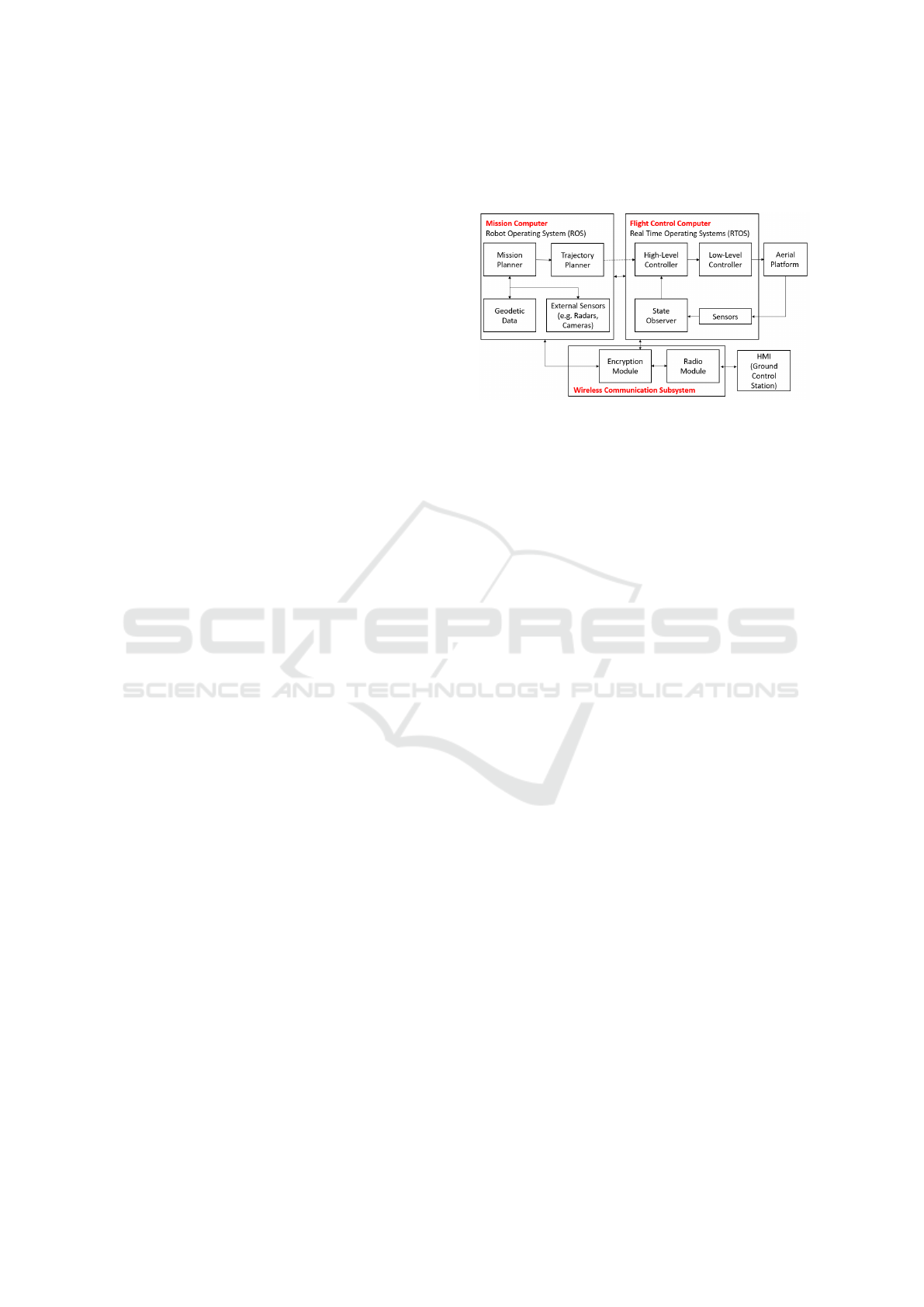
The architecture of the developed system shown in
Fig. 1 has been divided into three main compo-
nents: Mission Computer (MC), Flight Control Com-
puter (FCC) and Wireless Communication Subsys-
tems (WCS). This article does not deal with the radio
link subsystem. Human-Machine-Interface (HMI) is
dedicated software for managing the unmanned sys-
tem located at the Ground Control Station (GCS). The
flight controller (High-Level Controller) consists of
three main subsystems:
• Stabilization of the platform - algorithms based on
PID regulators, which are designed to stabilize the
angular position of the UAV in space.
• Stabilization and control of the height, vertical
speed and flight speed of the platform - these al-
gorithms are also based on PID controllers sup-
ported by state machines and mathematical algo-
rithms based on energy estimation.
• Navigation algorithms - course control, flight
along a given route, line, etc. These algorithms
were also based on PID regulators supported by
mathematical algorithms and input/output signal
shaping systems.
The High-Level Controller, on the basis of the set
values and determined by the State Observer, deter-
mines the required deflections of the controls and the
propulsion system, so that the platform performs the
set flight parameters.
Figure 1: Diagram of the architecture of the unmanned
aerial platform.
The Low-Level Controller is responsible for con-
verting the signals developed by the High-Level Con-
troller from angular and percentage values to appro-
priate hardware values enabling the control of servos,
motor controllers or other actuators.
In the architecture presented in the work, MC is
based on the ROS. The algorithms for determining
the flight trajectory are supported by geodetic data,
other reconnaissance data and external auxiliary sen-
sors. ROS is a dedicated suite of libraries and soft-
ware for developing robotics software. Thanks to it,
in the presented architecture it was possible to divide
the software architecture into smaller modules, the so-
called nodes.
3.2 Modeling Autonomy
The functional requirements for UAV usually come
from two sources. The first of them are customer
requirements in terms of system functionality. The
second source is the requirements imposed by safety
standards. They are defined as part of the Functional
Risk Analysis (FHA) documents. All the defined re-
quirements are the basis for the development of the
system architecture and a detailed description of the
scenarios of the operation of the air platform per-
forming the reconnaissance task. Each functional re-
quirement is transformed into a system performance
scenario or a single function of the designed system.
The following parts of the article present examples of
UAV operation models that take into account three se-
lected flight scenarios:
• flight in contact with the GCS (the radio link is
not disturbed and the GPS is working properly)
• flight without communication with GCS in the
presence of gusts of wind on the route segment
where SAR radar is used
Increasing the Autonomy of the Unmanned Aerial Platform
367
• flight in the event of detection of a potential air
collision of two air platforms equipped with ADS-
B (Automatic Dependent Surveillance - Broad-
cast) systems.
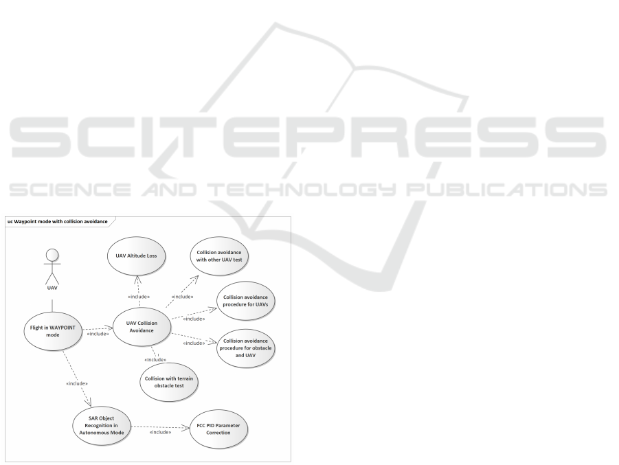
Figure 2 shows an example of a Use Case dia-
gram covering the scenarios presented in the article
(Use Case is a way of modeling the fulfillment of re-
quirements by system functions). The article presents
the UAV architecture that allows the MC to modify
the operation of PID controllers built into the FCC.
Modifications to the setting of the maximum allow-
able platform roll in flight were presented. In the fur-
ther part of the work, we assumed that the functional
analysis of the system operation (FHA) showed that
during the flight of the platform, a collision may oc-
cur with another aircraft equipped with ADS-B. We
also assume that the UAV may not be in contact with
the GCS in the time preceding the collision. If, during
detection of a potential collision, the UAV had radio
contact with the GCS, the platform will not take any
action and will wait for the controls sent by the pi-
lot. We also assume that the UAV is equipped with
ADS-B with the ability to receive the signal gener-
ated by other aviation platforms. Otherwise, the sys-
tem should only prompt the pilot on possible actions,
but the final decision must always be with the pi-
lot. Moreover, other flying platforms must also have
ADS-B or Sense and Avoid systems. Otherwise, the
UAV will not have enough data to react. Based on
these assumptions, the model presented in the article
was developed.
Figure 2: Use Case that aggregates activities supporting an
autonomy of UAV.
Figure 2 shows the Use Case model, which de-
scribes the possible activities during the UAV flight
along the given waypoints (often referred to as the
WAYPOINT mode). The figure shows the basic case
(basic scenario) - Flight in WAYPOINT mode, which
includes scenarios related to autonomous operation
(without contact with GCS) and actions required in
the event of hazardous situations. The autonomous
scenarios are represented by the SAR Object Recog-
nition in Autonomous Mode scenario. This scenario
includes support for the FCC PID Parameter Correc-
tion scenario that allows UAV roll limitation during
target recognition using SAR.
Hazardous scenarios are described by the collec-
tion of UAV Collision Avoidance scenarios, which is
included in the main scenario. This group includes
procedures for handling a sudden loss of flight alti-
tude by UAVs, response to a potential air collision
with another platform, and response to a terrain ob-
stacle, etc.
Figure 3 shows a state machine model that de-
scribes the operation of the system in flight along
predefined route points. The model shows three or-
thogonal states. Actions described in these states can
be performed in parallel. In the presented simpli-
fied case, in the first orthogonal state, the actions per-
formed during the flight over the points were defined.
In this state, the FCC and MC cooperate with each
other, with the assumption that the MC takes over the
reconnaissance service using SAR and the FCC con-
trols the flight of the UAV. Details are presented in
Section 3.3.
The second state shows the handling of the highest
level tactical situation related to the uncontrolled loss
of flight altitude by the UAV. In this state, the FCC
software activates the parachute if it is not possible to
stop the uncontrolled fall of the UAV. This is the usual
procedure for small drones.
In the third orthogonal state, there are procedures
for handling situations related to potential collisions.
Due to the fact that in this case detection of collisions
and determination of a new flight trajectory requires
some computing power, MC is responsible for han-
dling this group of situations. Critical functions from
this group are performed serially in a separate thread
of the MC computer, which is required by the flight
safety rules.
The basic scenario carried out by a UAV that per-
forms a flight along a predefined route consists in go-
ing through the following states in sequence:
FW M1 → FW M2 → FW M3 → FW M2 →
SUP → FW M1 (selection of the next waypoint, flight
to a point, optional configuration of the recognition
sensor, checking the threat status and going to the se-
lection of the next waypoint).
In the case when the UAV starts recognition with
the use of SAR at a given point, the weather condi-
tions are tested at the input in the FWM3 state (en-
ICSOFT 2022 - 17th International Conference on Software Technologies
368
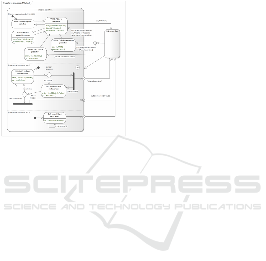
Figure 3: State machine presenting some typical excep-
tional situation handling.
try:checkWindParams()). The UAV’s allowable roll
angle is then calculated in the main state routine
(do:calculateFCCparams()) (see the 3.3). In case of
strong wind, the MC sends a request to the FCC to
minimize the roll angle. On the input of the FWM2
state in the function (entry:checkRecognition()) it is
checked whether the recognition will be performed
on the route segment with the use of a given sensor
type. If so, the do:setFCCparams() procedure is run,
which sets the maximum allowed UAV roll angle. On
exiting the state in the exit:resetFCCparams() proce-
dure, the default parameters of the sensor settings are
restored.
The described approach is very simplified and
presents only the most important elements related to
the reconnaissance carried out on the flight segment.
Note that the procedures described in the states (en-
try:, do:, exit:) are then detailed in the form of se-
quence or activity diagrams.
An alternative processing scenario will occur
when a dangerous situation is detected in one of the
other orthogonal states. At the same time, it should
be remembered that the detection of a sudden loss
of height performed by the FCC has a higher prior-
ity than the detection of a potential collision (which
is supervised by the MC). It’s not so obvious why
the FCC-designated state takes precedence. How-
ever, when the reader realizes that the sudden loss of
UAV flight altitude is associated with the immediate
loss of communication with GCS, it becomes clear
that the UAV must react to such a state faster than to
any other. The supervisor module is responsible for
the appropriate assessment of the importance of the
states, which is shown on the model in the form of the
SUPERVISOR state.
When a dangerous situation is detected regarding
a possible collision with another platform or a colli-
sion with a terrain obstacle, the processing sequence
is as follows.
FW M1 → FW M2 → SUP → FW M4 →
FW M2 → SUP → FW M1 (following waypoint
selection, flight to point, emergency test, emergency
collision avoidance, a continuation of the flight to a
point, a test of the occurrence of an emergency, and
selection of the next waypoint). do:testCollision()
and do:findWPT() are given numerical algorithms
that are used to implement them. Collision testing
is performed according to algorithms presented in
(Stecz and Gromada, 2022). It is worth noting that
the determination of the collision situation using the
geometric methods takes a short time so that indi-
vidual tests can be performed sequentially without
risk.
As part of handling emergency situations, poten-
tial collisions between air platforms and a collision
with a terrain obstacle are investigated (see states
ExS1 and ExS2). Of course, this set also includes the
emergency situation related to the UAV crossing the
border of the mission area. Since this group of states
may have the same priority, the MC algorithms must
work efficiently enough to verify in a very short time
which of the situations may occur in the foreseeable
future. For example, in the event of a potential colli-
sion with a terrain obstacle, UAV algorithms must de-
termine the route point above the obstacle. By default,
the platform can lower the flight altitude in certain sit-
uations, which is not possible in the event of a poten-
tial collision with a terrain obstacle. The processing
itself is strictly dependent on the adopted principles
of UAV operation and conditions beyond the scope of
the article.
When an uncontrolled loss of height is detected
directly threatening the UAV, the processing sequence
is as follows.
FW M1 → FW M2 → SUP → FW M5 →
FW M2 → SUP (after selecting a waypoint, flight to
a point, emergency test, UAV flight stabilization or
parachute release, flight continuation to a point after
successful UAV stabilization, test the occurrence of
an emergency situation). If the attempt to stabilize
the flight fails, the parachute discharge ends the UAV
flight.
The reader can see that the state machines do not
need to show a clear separation of the tasks of the in-
dividual computers (in this case the FCC and MC).
Increasing the Autonomy of the Unmanned Aerial Platform
369
State machines are an abstract description of the op-
eration of a system that allows for the presentation
of the concurrent operation of its components. If it
is necessary to assign individual procedures to equip-
ment, a diagram detailing the data processing method
should be drawn for each of the procedures listed on
the basis of state machines. Only such a diagram can
be assigned to a specific resource on which processing
takes place. It is important to emphasize once again
that according to the concept of UML and SysML, the
actions described in states are processing algorithms
detailed in the form of sequence or activity diagrams.
When procedures belonging to states can be de-
scribed with numerical algorithms, there is no need
to generate additional activity diagrams and connect
them with state machines. It is worth bearing in mind,
however, that adding an additional, very simplified di-
agram, in which one or two activities is described, is
useful for the purposes of mapping low-level require-
ments into implemented functions. Therefore, it is not
worth skipping this step.
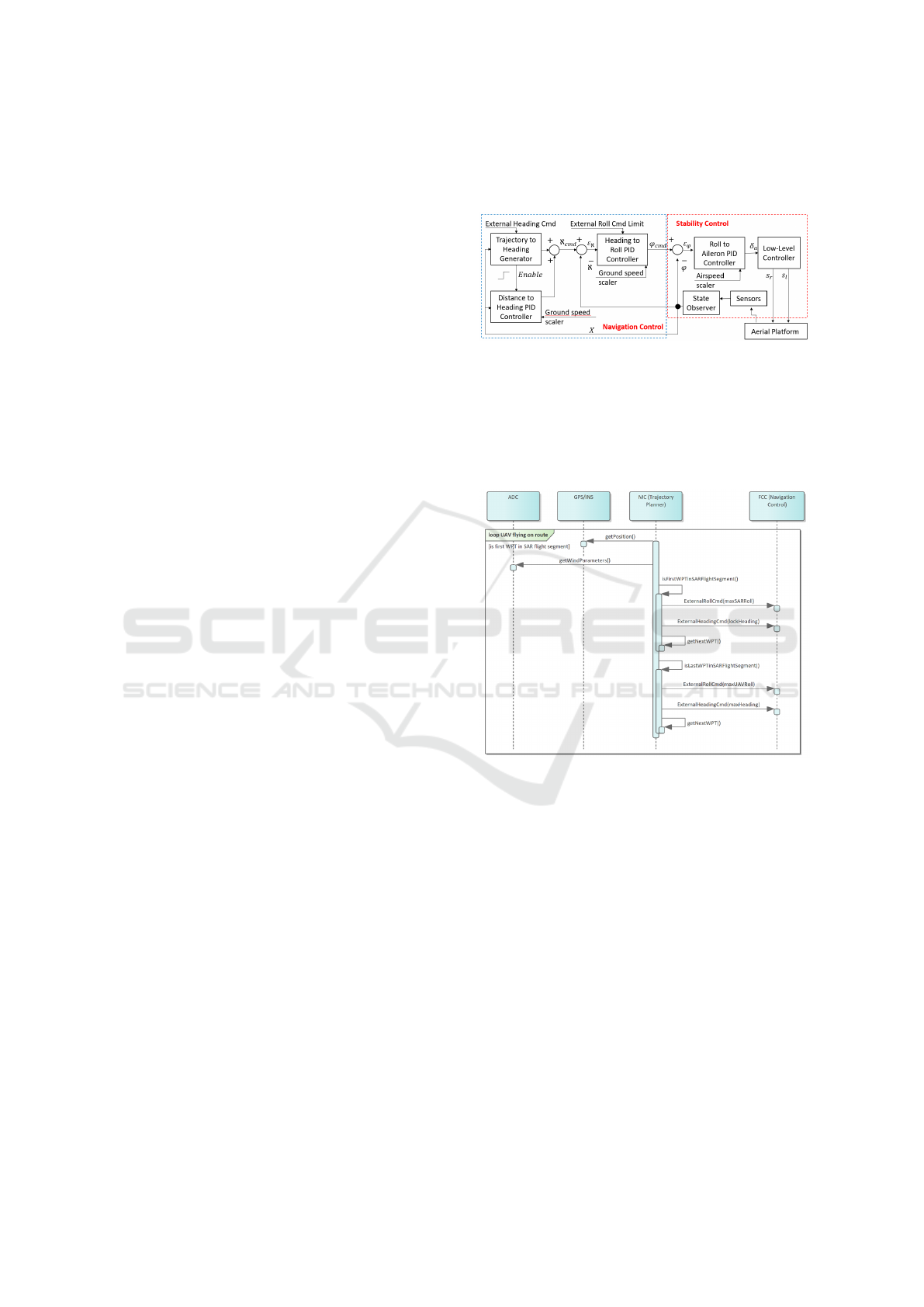
3.3 MC and FCC Integration
The integration of FCC and MC will be described
on the example of correcting the PID parameters (see
Fig. 4) by the MC during the flight on the route seg-
ment where the SAR radar was used, when the con-
trol of the UAV’s roll angle is very important. De-
tailed rules of SAR operation are described in the
work (Stecz and Gromada, 2020). It is worth men-
tioning that in order to perform a correct surface scan,
the SAR must scan through a flight segment of the
length equal to the so-called synthetic aperture. The
greater the distance and the more accurate the scan,
the longer the flight segment must be - usually at least
several hundred meters. In this section, the roll angle
should be minimal and not more than a few degrees.
It is acceptable, however, that during the preparation
of the scan, the UAV will not keep the course and the
platform will be carried away by the wind.
The most important thing when performing a SAR
scan is minimizing rolls. Therefore, the MC that con-
trols the scanning process must be able to interfere
with the maximum range of platform roll set by the
FCC in its regulators when flying between waypoints.
This is what the External Roll Command Limit con-
trol input is for. The scheme of the roll angle control
procedure for the described situation in the SysML
modeling language in the form of a sequence diagram
is shown in Fig. 5. The MC software checks in a
loop whether the UAV has reached the point that is
the beginning of the SAR recognition segment. If so,
MC, having data on wind parameters, sets the maxi-
mum allowable platform roll. Additionally, it sets the
value of the Heading parameter, which indicates the
direction of the UAV flight.
Figure 4: Block diagram of FCC built-in PID controllers.
Two types of control blocks are visible: the UAV navigation
block and the UAV stability control block.
When the UAV leaves the reconnaissance route
segment, the default values of the allowable platform
roll angles are restored, which allows you to return to
the commanded trajectory.
Figure 5: Diagram of the procedure for controlling the UAV
roll angle during the recognition of the object by the SAR.
ADC provides data on wind conditions. Data is exchanged
between MC and FCC. MC is responsible for setting the
maximum allowable roll angle.
In some situations it is also useful to maintain a
given UAV course, which the MC may impose on the
FCC controllers. Course control is used in practice
when the MC detects a dangerous situation and ana-
lyzes it for a specified period of time. In this case, the
UAV switches to the flight mode for the set course at
the minimum allowable speed, which is safe for the
UAV under the given conditions. The MC calculates
and sends the desired course to the PID controller in
the control block. Depending on the weather condi-
tions, the speed relative to the ground may also be
reduced, which allows to limit the length of the UAV
flight, during which the UAV carries out self-testing
procedures of the systems. This is what the Exter-
nal Heading command control input is for. When MC
ICSOFT 2022 - 17th International Conference on Software Technologies
370
sets a heading, the Enable signal is set for Distance to
Heading PID Controller.
4 RESULTS
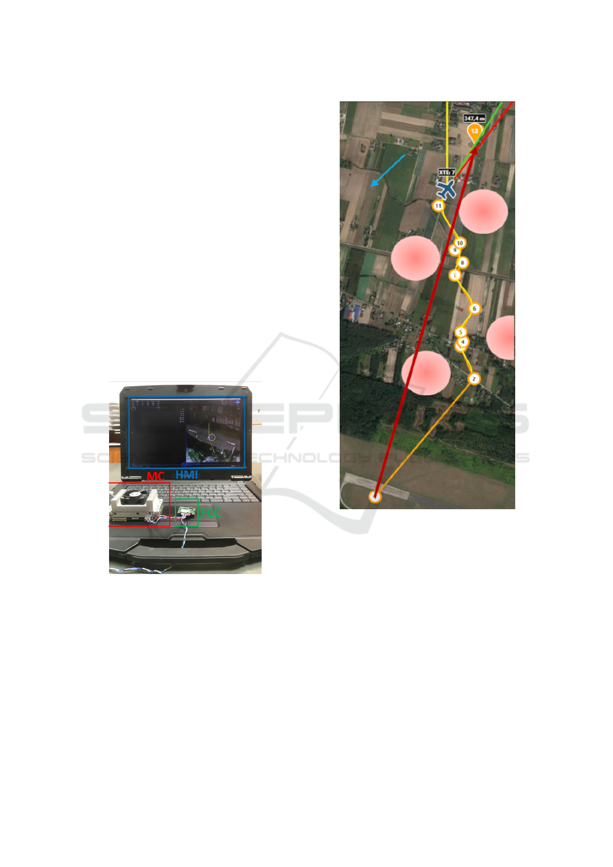
Operation of the described platform was tested in a
simulation environment, the architecture of which is
presented in Fig. 6. A Hardware-in-the-Loop envi-
ronment was built in which the physical FCC and MC
devices (on which the target software was installed)
were integrated. Only the position reported to the
FCC and MC by GPS/INS and ADC was simulated.
The operation of other on-board equipment was not
simulated as it was not necessary for the purpose of
the research. Changes in wind strength and direction
as well as wind gusts were simulated by a component
imitating ADC. It was assumed that the wind direc-
tion and speed were within the limits set for this type
of UAV. This also applied to gusts of wind. Such as-
sumptions are correct because the UAV has a greater
tolerance to the wind force than the SAR radar, which
should work in conditions without platform roll.
Figure 6: HIL simulation architecture of the unmanned
aerial platform.
Fig. 7 shows result of simulation performed in
HIL test of route planned and control algorithms de-
scribed above. For the clarity, only UAV flights on
one of the route segments of the designated route have
been considered.
Another simulation was carried out with a view to
checking the functioning of the bank angle limitation
algorithm for the implementation of the SAR mission.
The Fig. 8 shows the flight trajectory without limiting
the bank angle value. This figure shows that despite
the disturbances in the form of wind, UAV follows
Figure 7: Simulated UAV trajectory for predefined wind
speed and direction.
the route according to the designated path. However,
in the case of flight with a bank angle limitation of 5
degrees for SAR missions, the UAV continues to try
to follow the given path shown in Fig. 9. However,
the predefined path is achieved after a much greater
adjustment time. This time is due to the fact that the
minimum turning radius of the air platform has in-
creased.
On the other hand, UAV is still able to follow
the given route. However, in this case, the MC must
take into account the change in maneuverability of the
UAV platform when correcting the mission.
Increasing the Autonomy of the Unmanned Aerial Platform
371
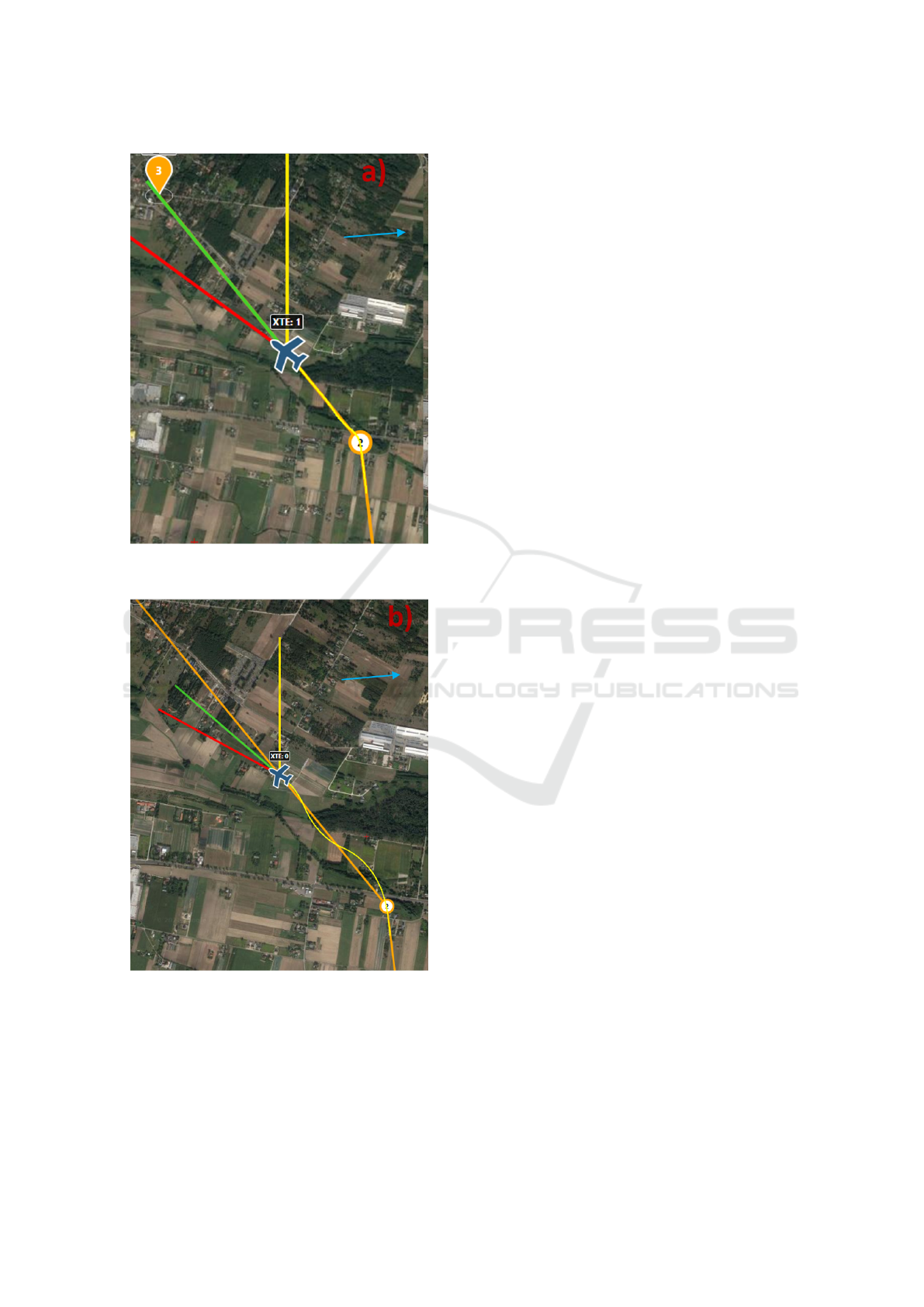
Figure 8: An example of a UAV flight simulation on a sec-
tion when FCC has no restrictions on platform roll.
Figure 9: An example of a UAV flight simulation on a route
segment, when the maximum roll angle of the UAV has
been defined.
5 CONCLUSIONS
The article presents the principles of designing reli-
able architecture supporting UAV control, taking into
account the need to handle exceptional situations oc-
curring during the flight. At the same time, the set of
exceptional situations includes all situations that en-
sure the safety of the UAV flight while ensuring its
correct operation in the event of loss of contact with
the GCS.
The architecture of modern unmanned aerial plat-
forms with built-in capability to carry out autonomous
missions was characterized in detail. Architecture
requires the integration of UAV systems with flight
route planning and correction algorithms. Particular
attention was paid to UAV flight methods in the con-
ditions of wind gusts, the occurrence of which causes
great difficulties related to the recognition of objects
with the use of SAR radars.
The article refers to the algorithms that ensure,
above all, the safety of the autonomous UAV flight.
All these algorithms must be implemented on the
platform operating in changing weather conditions in
zones where other air platforms may also appear. Of
course, the presented approach does not ensure the
safety of the UAV while flying in any terrain. Cer-
tain assumptions were made in the work, which do
not always have to be met. For example, in order for
a UAV to avoid a collision with another UAV, it must
be equipped with ADS-B and each platform moving
in the area where the UAV is operating must also have
a position warning system. Without it, it is impossible
to detect a potential air collision.
An important element pointed out in the article are
the principles of modeling the hierarchy of handling
exceptional situations. Situations such as the sudden
loss of UAV altitude or the detection of a collision
with another air platform have the priority of service
much higher than the detection of problems with the
completion of the task in the assumed time.
The integration of mission management methods
and methods of handling emergency situations, tak-
ing into account wind conditions, is an innovative ele-
ment of the work. The research was carried out on the
basis of the UAV mathematical model developed for
the needs of the platform designed by ITWL, which
took into account the stabilization and navigation al-
gorithms and the wind turbulence model according to
Dryden’s concept.
The direction of further work concerns greater in-
tegration of the developed methods with the methods
of automatic detection of failures of devices constitut-
ing the equipment of the air platform.
ICSOFT 2022 - 17th International Conference on Software Technologies
372

ACKNOWLEDGEMENTS
The presented results were prepared with the use of
UAV models developed by ITWL.
REFERENCES
Boubeta-Puig, J., Moguel, E., S
´
anchez-Figueroa, F.,
Hern
´
andez, J., and Carlos Preciado, J. (2018). An au-
tonomous uav architecture for remote sensing and in-
telligent decision-making. IEEE Internet Computing,
22(3).
Carvalho, J., Juc
´
a, M., Menezes, A., Olivi, L., Marcato, A.,
and dos Santos, A. (2017). Autonomous uav outdoor
flight controlled by an embedded system using odroid
and ros. 402:58–67.
Ilarslan, M., Bayrakceken, M. K., and Arisoy, A.
(2011). Avionics system design of a mini vtol uav.
IEEE Aerospace and Electronic Systems Magazine,
26(10):35–40.
Sanchez-Lopez, J., Pestana, J., and de la Puente, P. (2016).
A reliable open-source system architecture for the fast
designing and prototyping of autonomous multi-uav
systems: Simulation and experimentation. J Intell
Robot Syst, 84:779–797.
Siemiatkowska, B. and Stecz, W. (2021). A framework for
planning and execution of drone swarm missions in a
hostile environment. Sensors, 21(12).
Stecz, W. and Gromada, K. (2020). Determining uav flight
trajectory for target recognition using eo/ir and sar.
Sensors, 20.
Stecz, W. and Gromada, K. (2022). Designing a reliable
uav architecture operating in a real environment. Appl.
Sci., 12(294).
Stecz, W. and Kowaleczko, P. (2021). Designing oper-
ational safety procedures for uav according to nato
architecture framework. In Proceedings of the 16th
International Conference on Software Technologies -
ICSOFT,, pages 135–142. INSTICC, SciTePress.
Wang, Y., Lei, H., Hackett, R., and Beeby, M. (2019).
Safety assessment process optimization for integrated
modular avionics. IEEE Aerospace and Electronic
Systems Magazine, 34(11):58–67.
Zhang, M., Qin, H., Lan, M., Lin, J., Wang, S., Liu, K., Lin,
F., and Chen, B. M. (2015). A high fidelity simulator
for a quadrotor uav using ros and gazebo. In IECON
2015 - 41st Annual Conference of the IEEE Industrial
Electronics Society, pages 002846–002851.
Increasing the Autonomy of the Unmanned Aerial Platform
373
