
Configuration Settings on Nokia 7750 SR Routers to Optimize Network
Performance
Indrit Enesi
1 a
and Anduel Kuqi
2 b
1
Faculty of Information Technology, Polytechnic University of Tirana, ”Mother Teresa” Square, Tirana, Albania
2
Department of Core Network, One Telecommunication, Tirana, Albania
Keywords:
Nokia Router 7750, Configuration Parameter, LAG, SAP, QoS.
Abstract:
One of the main advantages of the Nokia 7750 SR-7 / SR-12 router type is the fact that it meets the most
advanced innovations of the time, enabling a network of very high performance (high capacity and speed).
But even in these types of routers there are configurations which must be avoided in order to obtain exactly
the optimal performance. In this paper we will treat two configurations for 7750 SR-7 which led to a problem
where there was not enough capacity in the LAG and we will replace the configurations in order to have
optimal parameters.
1 INTRODUCTION
Nokia Service Routers (SR) are undoubtedly one of
the best network design options for many factors in-
cluding: meeting the most advanced innovations of
the time, enabling a very high performance network .
In addition to the current market demands for high ca-
pacity and speed, this class of routers also enables the
support of Cloud, 5G networks as well as the Internet
of Things. This family of routers includes the follow-
ing types: 7750 SR, 7750 SR-s, 7750 SR-a and 7750
SR-e. Capacity processing by these types of routers
ranges from 200 Gb/s to 13.5 Tb/s . It is worth not-
ing that these types of routers fit networks of different
sizes as well as support Gigabit Ethernet interfaces as
GE, 10GE, 100GE, 400GE . In this paper it is consid-
ered a network where router type 7750 SR-12 repre-
sents a core router and the other type 7750 SR-12 rep-
resent a BGW (Border Gateway Router) router. The
focus stands on the optimal use of network parts, two
configurations for the BGW router 7750 SR-7 will be
addressed, which resulted in a drop in traffic above a
certain value, resulting in QoS problem. New config-
urations will be implemented in order to have a ca-
pacity optimization.
a
https://orcid.org/0000-0002-2695-2726
b
https://orcid.org/0000-0002-7141-0475
2 NETWORK STRUCTURE
The network structure that is considered for the anal-
ysis of the problem is composed by the part of core
routers and the part of routers that serve for Internet
access. In the role of core router we have the type
Nokia 7750 SR-12 while as outbound routers on the
Internet we have the type Nokia 7750 SR-7. To have a
clear view of the problem, the network diagram used
is shown in figure 1.
Figure 1: Network diagram.
In the diagram shown above, the routers R1 and
R3 have the role of BGW routers type nokia 7750
SR-7, while routers R5 and R7 have the role of core
routers type nokia 7750 SR-12. One technological
Enesi, I. and Kuqi, A.
Configuration Settings on Nokia 7750 SR Routers to Optimize Network Performance.
DOI: 10.5220/0011094100003179
In Proceedings of the 24th International Conference on Enterprise Information Systems (ICEIS 2022) - Volume 2, pages 597-600
ISBN: 978-989-758-569-2; ISSN: 2184-4992
Copyright
c
2022 by SCITEPRESS – Science and Technology Publications, Lda. All rights reserved
597
aspect that definitely favors Nokia’s choice of tech-
nology is the increase in Link capacity without the
need to upgrade hardware components to have higher
speeds (Lapukhov et al., 2016). On Nokia routers
this is enabled using Link Aggregation Group ( LAG)
(LAG, 2011). So depending on the capacity required
the router card ports (which can be at the same or dif-
ferent speeds) are mixed and form a LAG with a ca-
pacity equal to the sum of the capacities of each port.
The LAG also offers stability, so if a LAG fails for
various reasons then the standby LAG will take over
the passage of traffic (Bhatia, 2014). In the above di-
agram we have specifically LAG 5 for the connection
between R1 and R5, LAG 5 for the connection be-
tween R3 and R7, LAG 2 for the connection between
R1 and R3, while LAG 10 in each of the BGW routers
(R1 and R3) we have it for the output on the Internet,
more specifically are the LAGs that connect end-to-
end between our network and the ISP (Internet Ser-
vice Provider). LAG 10 in R3 is also the primary line
for the end-to-end connection with the ISP while LAG
10 in R1 is in the standby state, which means that if
for various reasons LAG 10 to R3 (reasons related to
the LAG itself for example fiber damages, reasons re-
lated to the router itself or the router card where we
created the LAG is in trouble) is no longer in work-
ing condition then the active role will pass LAG 10 to
R1. So the above description is known as the principle
of redundancy (specifically, one runs as the primary
router and the other as a backup router). In our case
both LAG 10 on each router (R1 and R3) are termi-
nated on the same ISP. Sincewe have taken as active
LAG the LAG 10 at R3 after the traffic comes to this
router from the ISP we send this traffic to the chorus
routers which are in our case R5 and R7. We see again
as in the case of BGW routers in the core part we have
two routers and again we apply the principle of re-
dundancy where R7 acts as the primary core router,
so the traffic coming to R3 via LAG 5 will be sent to
router R7. If for various reasons router R7 is not in
working conditions or LAG 5 from R3 to R7 is dys-
functional then the traffic coming from ISP to router
R3 must be routed in alternate routes in order for the
traffic to end at the core router R5 (which serves as
a standby router). To send traffic from R3 to R5 ini-
tially through LAG 2 we will send the traffic from
R3 to R1 and here through LAG 5 we will send the
traffic from R1 to R5. Each service is uniquely iden-
tified by a service ID and an optional service name
within a service area (Bhatia, 2014). The Nokia ser-
vice router model uses logical service entities to con-
struct a service (Documentation, 2020). In the Nokia
router services can provide Layer 2 bridged service or
Layer 3 IP-routed connectivity between a service ac-
cess point (SAP) on one router and another service ac-
cess point (a SAP is where traffic enters and exits the
service) on the same ( local) router or another router
(distributed). A distributed service spans more than
one router (Bhatia, 2014) . Common to all Nokia ser-
vice router connectivity services are policies that are
assigned to the service (Documentation, 2020). Poli-
cies are defined at a global level and then applied to a
service on the router (Nokia, 2017). Policies are used
to define Nokia service router service enhancements
(Nokia, 2019a). One type of policies that is common
to the router’s connectivity services is –SAP Quality
of Service (QoS) policies which allow for different
classes of traffic within a service at SAP ingress and
SAP egress (Nokia, 2017). QoS ingress and egress
policies determine the QoS characteristics for a SAP
(Alcatel-Lucent, 2012). A QoS policy applied to a
SAP specifies the number of queues, queue character-
istics (such as forwarding class, committed, and peak
information rates, and so on) and the mapping of traf-
fic to a forwarding class (Router, 2017). A QoS policy
must be created before it can be applied to a SAP. A
single ingress and a single egress QoS policy can be
associated with a SAP (Nokia, 2019b). The QoS pol-
icy of inbound (ingress) services defines how incom-
ing traffic to an SAP is classified and ranked before it
is forwarded to the outbound.The QoS policy of out-
bound services (egress) determines how traffic will be
served just before it is forwarded to an SAP.
2.1 Experimental Analysis
In SAP-INGRESS QoS Policy and SAP-EGRESS
QoSPolicy , if we use the percent-rate command as
well as in the LAG configuration we use the adapt-qos
distribute command, then a traffic cut will be noticed.
Logically if ”percent-rate” is used and the gate is ac-
tually a LAG then a 100 PIR should give a rate equal
to the capacity of the LAG. Analyzing traffic it is no-
ticed that the calculation is actually based on a single
gate, which yields in traffic intersection, the graphical
representation of which is given in figures 2 and 3.
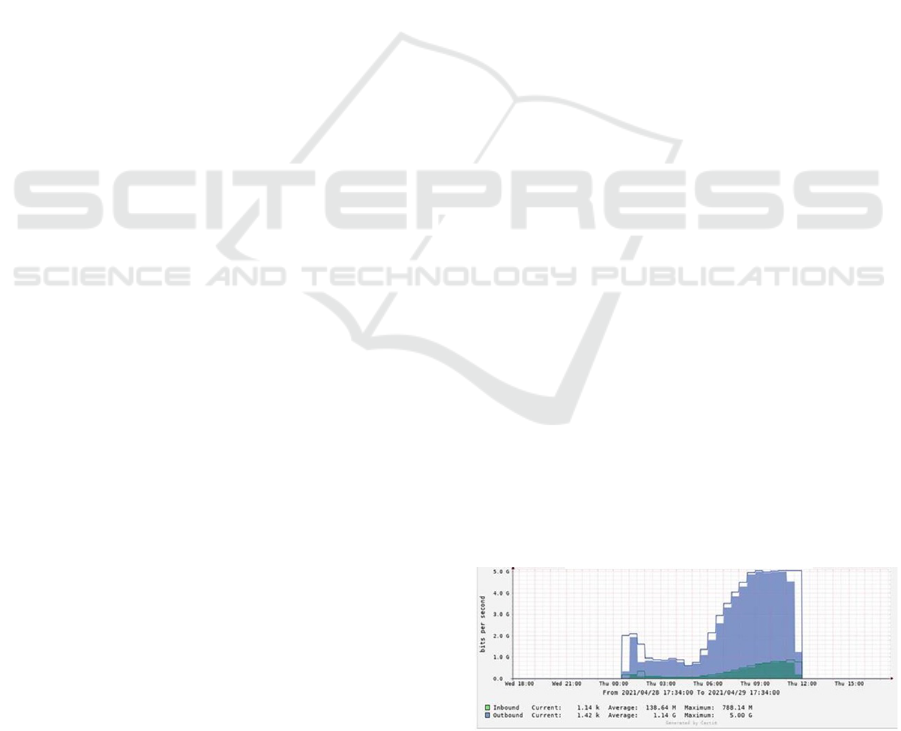
Figure 2: Traffic chart link 1 in LAG 10 to R3.
LAG-s taken into consideration in the router 7750
SR-7 are created with two ports each with a capacity
ICEIS 2022 - 24th International Conference on Enterprise Information Systems
598
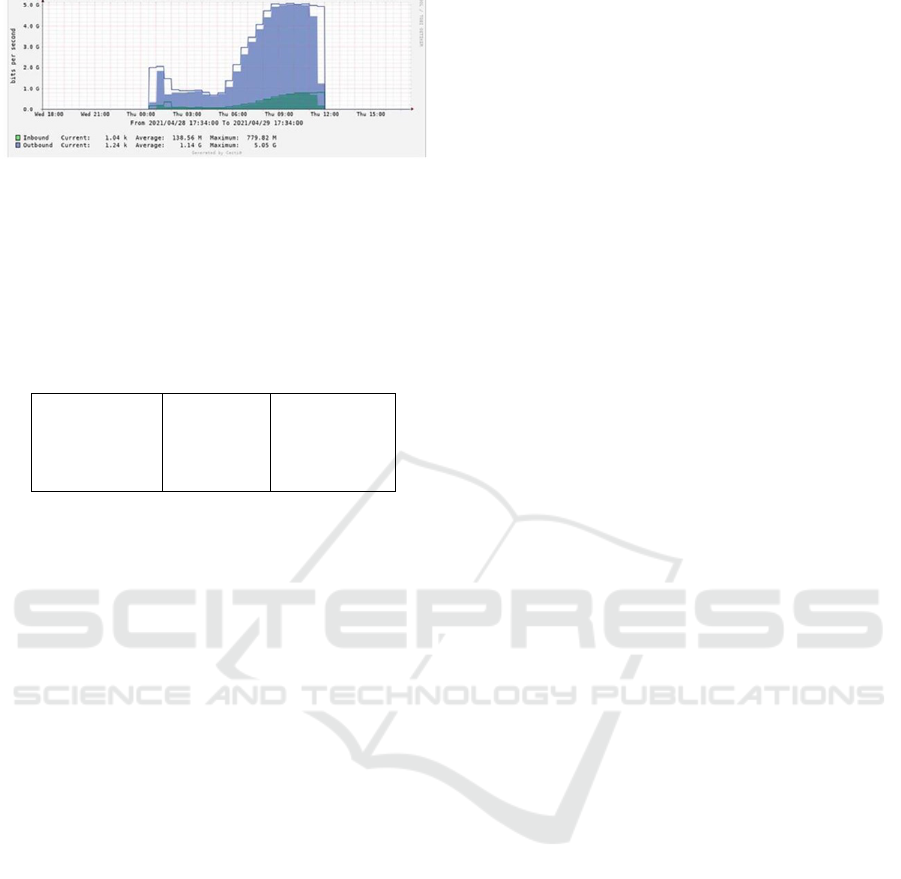
Figure 3: Traffic chart link 2 in LAG 10 to R3.
of 10G (in total the capacity of the LAG is 20G). But
it was noticed that in both ports after 5G is reached
(10 in total in both ports) the packages drop, a result
that is given in figures 2 and 3.
We can see the above result from the statistics pre-
sented in table 1.
Table 1: Statistics with initial configurations.
Sap Aggregate Stats
Ingress Packets Octets
Aggregate Offered: 16175424500708 19592527617233612
Aggregate Forwarded: 16111167561540 19517514259173874
Aggregate dropped: 642569399158 75013358047414
Egress
Aggregate Forwarded: 10624079953591 1982395480328978
The percent-rate command within the QoS policy
in SAP ingress and SAP egress allows the CIR and
PIR scales to be configured as a percentage of the
gateway exit rate. When we express the scale as a
limit port then the use of the current scale will vary
based on the gate speed. For example when the same
QoS policy on a 1 Gigabit Ethernet and 10 Gigabit
Ethernet gateway, then the next rate will be 10 times
higher on the 10 Gigabit port this is due to the differ-
ence in gateway speed.
This allows the same QoS on different SAP ports
without having to modify the next scale. The percent-
rate command is supported for pir and cir parame-
ters for both queues and policers (Nokia, 2017). Also
supported is the capability of specifying the rate as
a percentage value of the line rate for sap-ingress
and sap-egress qos policies. It is supported for both
queues and policers (Nokia, 2017). Syntax e pecent-
rate: percent-rate pir-percent [cir-percet] [port-limit
— local-time] percent-rate pir-percent police [port-
limit — local-limit]
The user has the option of specifying percent-rate
for pirand cirparameters (Nokia, 2017). PIR speci-
fies the maximum average rate at which traffic can be
planned in turn. Packets are forwarded only if the PIR
header is not packed. With each packet forwarded, a
token is added to the PIR head for each byte in the
packet. Pir-percent - this parameter is used to express
the pir order as a percentage dependent on port-limit
— local-time (Value varies from 0.01 to 100.00. The
default value is 100.00.) CIR is the guaranteed band-
width in the queue. As long as the CIR head is not
full, an additional package can again be forwarded
during the scheduled visit time. Cir-percent - Cir is
optional even when this is defined will express the
CIR queue as a percentage dependent on port-limit
— local-time (Value varies from 0.00 to 100.00. The
default value is 100.00.) (Nokia, 2019c). We also
provide details about the adapt-qos distribute com-
mand in the LAG configuration section. There are
three user-selectable modes that allow operator to best
adapt QoS configured to a LAG the SAPs are using
(Nokia, 2017)
1. adapt-qos distributed (default). In a distributed
mode the SLA is divided among all line cards
proportionally to the number of ports that exist
on that line card for a given LAG. The disadvan-
tage is that a single flow is limited to IOM’s share
of the SLA. This mode of operation may also re-
sult in underrun due to a ”hash error” (traffic not
sprayed equally over each link). This mode is best
suited for services that spray traffic over all links
of a LAG.
2. adapt-qos link. In a link mode the SLA is given to
each and every port of a LAG. The advantage of
this method is that a single flow can now achieve
the full SLA. The disadvantage is that the overall
SLA can be exceeded, if the flows span multiple
ports. This mode is best suited for services that
are guaranteed to hash to a single egress port.
3. adapt-qos distributed include-egr-hash-cfg. This
mode can be considered a mix of link and dis-
tributed mode. The mode uses the configured
hashing for LAG / SAP / service to choose either
link or distributed adapt-qos modes.
In terms of solution I need to make sure that the so-
lution allows full utilization of the resources of each
LAG in the network, has a functional qos mechanism,
is scalable and robust (in the sense that no qos con-
figuration changes will be required in case of adding
new ports to the LAG), the solution should also work
even if a new IOM card is added.
After a detailed analysis, 3 possible solution
options are ascertained: - Percent-rate (in SAP-
INGRESS QoS Policy and SAP-EGRESS QoS Pol-
icy) and adapt-qos link (to LAG configuration) -
Rate MAX (in SAP-INGRESS QoS Policy and SAP-
EGRESS QoS Policy) and adapt-qos link (to LAG
configuration) - Rate MAX (to SAP-INGRESS QoS
Policy and SAP-EGRESS QoS Policy) and adapt-qos
distribute (to LAG configuration)
When there is a LAG in adapt-qos distribute
(default mode) and this LAG carries a queue with
percent-rate ¡value¿ then this value is relative to the
capacity of one port and not relative to the capacity
Configuration Settings on Nokia 7750 SR Routers to Optimize Network Performance
599

of all LAGs. This is an expected behavior and not
a computer problem. In order to obtain percent-rate
based on the full capacity of the LAG, the adapt-qos
mode in the LAG has been changed from ”distribute”
to ”LINK” for egress. Network LAGs will work well
with solution 2 above, namely: configuring ”adapt
qos link” under SAP LAG interfaces and replacing
”percent rate” with the ”rate max” command . It is
worth noting that SAP LAG changes will be made
to each router in order for each LAG to operate at
100After the results performed with the selected tech-
nique described above as a result the traffic was nor-
malized. Reached about 12G traffic (based on gate-
way utilization). This is clearly shown in figure 4.
Figure 4: Traffic value in LAG 10 to R3.
Also from the table below it is noticed that we
have no more package drop.
Table 2: Statistics after changing configurations.
Sap Aggregate Stats
Ingress Packets Octets
Aggregate Offered: 4256776228302 5529986161549225
Aggregate Forwarded: 4256776228300 5529986161546349
Aggregate dropped: 0 0
Egress
Aggregate Forwarded: 6903957515520 1813015801778448
Aggregate dropped: 0 0
3 CONCLUSIONS
In this paper we treated two configurations for 7750
SR-7 which led to a problem where there was insuf-
ficient capacity in the LAG (a QoS problem), also we
presented the changes of these configurations through
which we obtained the optimal parameters. Using the
percent-rate command in SAP-INGRESS QoS Policy
and SAP-EGRESS QoS Policy as well as using the
adapt-qos distribute command in the LAG configura-
tion resulted in a traffic cut. By replacing percent-
rate with Rate MAX in SAP-INGRESS QoS Policy
and SAP-EGRESS QoS Policy as well as replacing
adapt-qos distribute with adapt-qos link in the LAG
configuration, an optimal capacity value in LAG was
obtained.
REFERENCES
Alcatel-Lucent (2012). Nokia service router. Accessed on
2012-05-07.
Bhatia (2014). Bidirectional forwarding detection on link
aggregation group interfaces. Internet Engineering
Task Force RFC.
Documentation, N. (2020). Nokia service router. Accessed
on 2021-11-11.
LAG (2011). Link aggregation. Accessed on 2021-07-07.
Lapukhov, P., Premji, A., and Mitchell, J. (2016). Use
of bgp for routing in large-scale data centers. In
Internet Requests for Comments RFC Editor RFC.
SCITEPRESS.
Nokia (2017). Nokia service router. Accessed on 2012-05-
07.
Nokia (2019a). Nokia service router. Accessed on 2012-
05-07.
Nokia (2019b). Nokia service router. Accessed on 2012-
11-11.
Nokia (2019c). Nokia service router in 5g. Accessed on
2021-05-07.
Router, N. S. (2017). Nokia service router. Accessed on
2012-05-07.
ICEIS 2022 - 24th International Conference on Enterprise Information Systems
600
