
From BPMN Model to Design Sequence Diagrams
Wiem Khlif, Samar Daoudi and Nadia Bouassida
Mir@cl Laboratory, University of Sfax, Sfax, Tunisia
Keywords: BPMN Model, Design Sequence Diagrams, Transformation.
Abstract: Today’s enterprises, independently of their size, depend on the successful development of an automated
Information System (IS). This moves them to the software development world. The success of this move is
often hindered by the difficulty in collecting the IS knowledge to produce a software that is aligned with the
business logic of the enterprise. For enterprise systems, this transformation must consider the enterprise
context where the system will be deployed. However, the complexity of today's Business Process (BP)-IS
alignment impedes their maintaining when the enterprise develops a new IS or changes its IS. The problem is
expressed from the dissimilarities in the knowledge of the information system developers and the business
process experts. To face these difficulties, the current paper presents a methodology to derive design sequence
diagrams. Our methodology is based on a set of rules that transform a business process model into design
sequence diagrams. Its originality resides in the Computation Independent Model (CIM) to Platform
Independent Model (PIM) transformations which account for the BP structural and semantic perspectives in
order to generate an aligned IS model.
1 INTRODUCTION
In the business world, a business process model
(BPM) represents a set of coordinated activities that
aim to accomplish business goals of any enterprise.
To facilitate the management of these goals, an
enterprise relies on an information system (IS). For
that reason, it is crucial to automate the IS supporting
the business process (BP) if its capacities are best
used. Conversely, this can not be gotten when the
business process is not aligned with its IS represented
by UML diagrams. Certainly, the alignment of these
models is key to the success of a coherent governance
of the enterprise (Aversano et al., 2016). In fact, it is
important to early start the IS modelling to obtain a
deep knowledge of the BPM. This step is crucial since
it prepares for requirement analysis.
In this context, the main problem is how to
produce and/or conserve the alignment between the
IS and BP models? This question has been attempted
within two scenarios. The first one inaugurate a
mapping approach between an existing IS and BP
(Aversano et al., 2016), or to analyze the impact of
BP changes on its IS (Rostami et al., 2017). If a
change of the IS model is needed, great efforts, is
required during the modification process to
accommodate the impact of changes. Therefore, the
need for an approach that deals with the changes of
models is of great value to software engineers.
The second scenario express the tight correlation
between the IS and objectives prompted researches to
extract requirements from business process models
denoted by UML use case diagrams, e.g. Rhazali et
al. (Rhazali et al., 2016); the relationships between
use cases, e.g. Berrocal et al. (Berrocal et al., 2014 ).
However, none of these approaches derives UML
diagrams that are documented with knowledge. In
addition, they differ in the degree of automation of the
proposed approach. Furthermore, the majority of the
works neglected the evaluation (i.e., quality,
precision, coverage) of the created diagrams.
In this research project, we focus on the second
scenario while offering a means for applying the first
scenario: we propose a model-driven approach to
automate the generation of the IS model from the BP
model. On the one hand, our approach can be used
to generate a new IS model that is aligned with the BP
model source. On the other hand, its generated IS
model can be used to identify the links between the
existing IS model and the BP model.
In (Khlif et al., 2018), we have presented a Model
Driven Architecture (MDA) approach called
DESTINY (a moDel-driven process aware
requiremenTs engineerINg methodologY).
Khlif, W., Daoudi, S. and Bouassida, N.
From BPMN Model to Design Sequence Diagrams.
DOI: 10.5220/0011089200003179
In Proceedings of the 24th International Conference on Enterprise Information Systems (ICEIS 2022) - Volume 2, pages 577-588
ISBN: 978-989-758-569-2; ISSN: 2184-4992
Copyright
c
2022 by SCITEPRESS – Science and Technology Publications, Lda. All rights reserved
577

It aims to automate the generation of use case,
system sequence diagrams and UML class diagrams
from BPMN models. The generated IS design can be
used either to establish a new IS system, or analyze or
maintain an existing one. It is defined in terms of
transformations that ensure the alignment of the
presented diagrams to the BPMN model by both
accounting for the semantics and structure of the
BPMN model, and providing for all business objects
and activities.
In this paper, we improve the DESTINY approach
(Khlif et al., 2018) with: 1) BPMN transformation
rules for identifying design sequence diagrams; 2)
implementing the obtained diagrams according to the
proposed transformation rules and evaluating them in
terms of their precision and domain coverage.
The rest of this paper is organized as follows. In
Section 2, we describe the related works of the
existing BP-IS alignment works. Section 3 presents
the transformation strategy rules that allow
transforming CIM models to PIM models. For a better
use of our approach, we develop in Section 4 a tool
for assessing the alignment between BPMN model
and the corresponding design sequence diagrams. In
Section 5, we conclude by specifying the current
works and by presenting future works.
2 RELATED WORK
In this section, we summarizes existing works on
aligning BPM to IS model.
Rhazali et al (Rhazali et al., 2016) the authors
propose a semi-automatic transformation from
Computation Independent Model (CIM) to platform-
independent model (PIM), based on rules.
In (Suchenia et al., 2017), the authors generate
UML sequence model from the BPMN model. Such
a model can support time specification such as
duration constraints or time constraints.
(Bouzidi et al., 2020) propose a set of rules that
transform a BPMN model into a UML sequence
diagram structured according to the model view
controller design pattern.
Overall, the above works related to BP-IS models
in (Suchenia et al., 2017) (Rhazali et al., 2016) are
purely structure-based; it ignores the remaining
aspects of a BP, which do affect the performance of a
BP. For example, the semantic type between objects
in a sequence diagram is not captured. In addition,
few are the works that automatically derive design
sequence diagrams from the BPMN model.
3 FROM BPMN TO DESIGN
SEQUENCE DIAGRAMS
To define the design sequence diagrams, we
decompose BPMN model into fragments. Each
fragment corresponds to a use case. A use case
represents a set of actions that the system(s) should or
can perform in collaboration with one or more
business workers or business actors, and it should
provide some observable result to them (Rumbaugh
et al., 2005). A business worker represents an
abstraction of a human that acts within the business
to realize a service, while a business actor represents
a role played by some person or system external to the
modeled business and interacting with the business.
Recall that we defined a pattern as a fragment F
in an annotated BPMN process model P, that is a
connected, directed sub-graph of P starting at one
activity and ending at another activity such that F
contains the maximum number of activities between
either two gateways, a start node and a gateway, or a
gateway and an end node. A fragment F can be
decomposed into sub-fragments if it contains sub-
processes, which indicates the end of sub-fragment
and the beginning of another one (khlif et al., 2018).
Since each use case is obsolete without a textual
or graphical description, we associated with each
BPMN-to-UCD pattern a set of BPMN-to-DSD rules
to model the use case behavior, which is 1:n mapping
between the concepts of BPMN model and design
sequence diagrams. To end this purpose, we lightly
extended the BPMN meta-model in (khlif et al., 2018)
to handle the business context. We added attributes
and two new classes that are Description and
ExtendedAttributes. For each BPMN element, we
associate a Description that adds a specific
information to BPMN elements in terms of the
relationships between them. The Extended Attributes
class specifies the properties of each BPMN element.
R1: For each lane whose label is a synonym to
"person", "agent" or "system", the corresponding
actor name will be the lane name. For each pool/lane
whose label is a metonymy of "department", "unit",
"division" or "management", the corresponding actor
name will be the concatenation of the pool/lane name
and the word “Agent” (khlif et al., 2018).
R2: For each pool:
R2.1: If the pool includes only business workers
(representing the system), then transform it to a set of
lifelines and an activation zone representing GUI,
entities and control classes that belong to the system
perimeter. The classes’ names follow the linguistic
ICEIS 2022 - 24th International Conference on Enterprise Information Systems
578

patterns presented above. They are extratced from the
obtained fragments.
R2.2: If the pool contains only business actors
then transform each business actor to a lifeline and an
activation zone for the instance of the actor. Apply R1
to rename the actor.
R3: For each lane representing a business worker,
then:
a. Add an actor corresponding to the lane; apply
R1 to rename it.
b. Add a lifeline and an activation zone for the
actor generated by R1.
R4: Transform each data to a
“BusinessObjectControler, “BusinessObjectGUI,
“BusinessObjectEntity”.
R5: For each extended attribute of the data
representing a complex noun, add:
a. “BusinessObjectEntity” corresponding to the
extended attribute if it represents a complex
noun.
R6: For each extended attribute representing a
complex noun 1 that depends on another complex
noun2, add a“BusinessObjectEntity” corresponding
to the complex noun 2.
R7: For each data having an extended attribute
representing a complex noun1 that depends on
another complex noun2:
a. Apply R4.
b. Add an asynchronous message from the actor
representing a lane to the
“BusinessObjectGUI” of the data. Then, add an
asynchronous message from the
“BusinessObjectGUI” to the
“BusinessObjectContr”. The message will be:
“add” followed by the data name.
c. Add a synchronous message from the
“BusinessObjectContr” of the data to the
“BusinessObjectentity” of the data. The
response label is a concatenation between the
BusinessObject and the passive voice of the
ActionVerb “Add”.
d. Add a synchronous message from the
“BusinessObjectContr” of the data to the
“BusinessObjectentity” of the complex noun1.
The message will be: “add” followed by the
complex noun1.
e. Add a synchronous message from the
“BusinessObjectContr” of the data to the
“BusinessObjectentity” of the complex noun2.
The message will be: “add” followed by the
complex noun2.
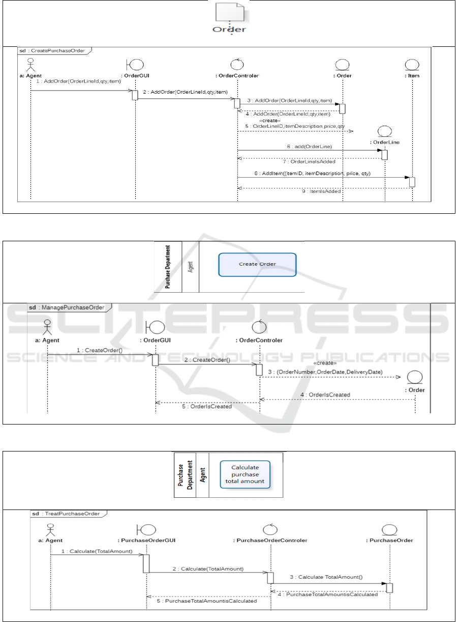
For instance, Figure 1 illustrates the annotated data
object in terms of extended attributes and description.
The description indicates a relationship between the
Purchase order data object and its extended attribute:
orderLine (Each Purchase order is composed of
order lines). The orderLine contains items (each
order lines contains a set of items). The extended
attributes of purchase order data object are
orderNumber, deliveryDate, orderDate, and
OrderLine. All of them are transformed into
parameters, except the
orderLine, which is
transformed into an entity. An orderLine contains the
attributes: orderLineID, item. All of them are
transformed into parameters, except the Item, which
is transformed into an entity.
R8: For each task performed in a lane, if the task
label respects the renaming pattern: « Action verb +
BusinessObject| NominalGroup », then generate the
elements of the sequence diagram by following these
steps:
R8.1: If the name of the task is « Action verb +
BusinessObject» (see Figure 2):
a. Add a new asynchronous message from the
actor corresponding to the lane, which is
already generated by R3.a, to the
“BusinessObjectGUI”. The message name is
ActionVerb().
b. Add a message from the
“BusinessObjectGUI” to the
“BusinessObjectControler” having the same
name of the message in (a).
c. Add a synchronous message having the same
name in (a) from the
“BusinessObjectControler” to the
“BusinessObjectEntity”. Add a response
message from the “BusinessObjetEntity” the
BusinessObjectControler. The response label
is a concatenation between the
BusinessObject and the passive voice of the
ActionVerb.
It is important to note that if the first activity SA
of a fragment F is labeled “Create x“, then the
corresponding DSD will be named “Manage x” (
Khlif
et al., 2018).
From BPMN Model to Design Sequence Diagrams
579
BPMN model
DSD
Figure 1: R7 illustration.
BPMN model
DSD
Figure 2: R8.1 illustration.
BPMN model
DSD
Figure 3: R8.2 illustration.
ICEIS 2022 - 24th International Conference on Enterprise Information Systems
580
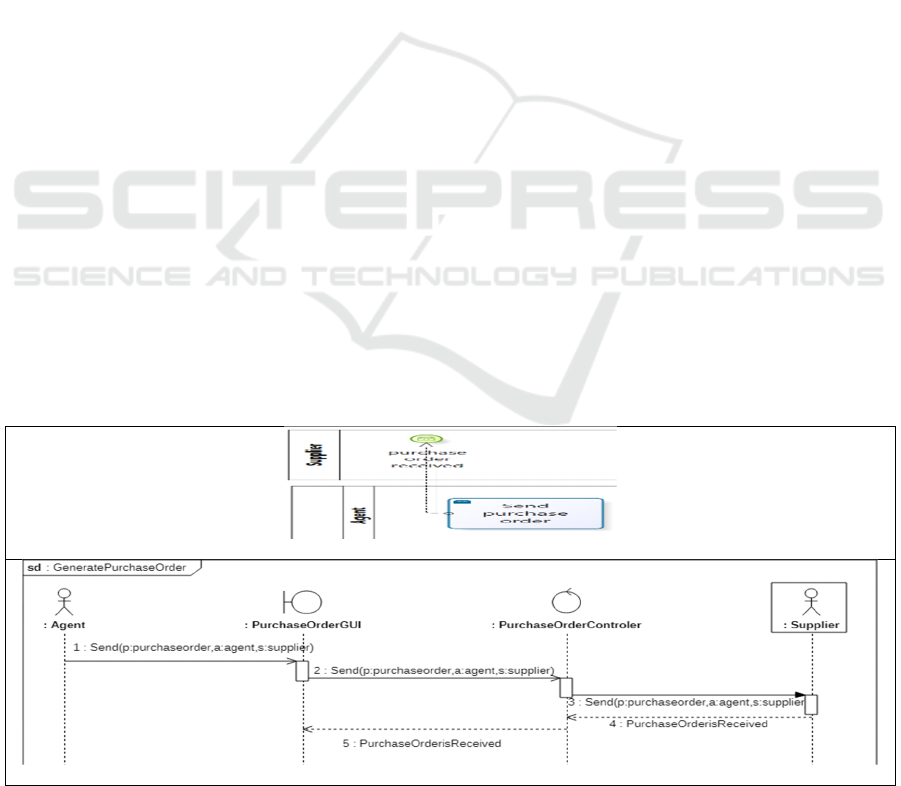
R8.2: If the name of the task is « Action verb +
NominalGroup», then (see Figure 3):
a. Add a new asynchronous message from the
actor corresponding to the lane, which is already
generated by R3, to the “BusinessObjectGUI”.
The message name is ActionVerb(). Another
message having the same name is sent from the
“BusinessObjectGUI” to the
“BusinessObjectControler”.
b. Add parameters to the identified method
ActionVerb() as follows: If the pre/post-
modifier is a noun that merely represents a pure
value, add it as a parameter. Otherwise, if the
pre/post modifier represents an entity, consider
the extended attributes of the entity, as
parameters of the method ActionVerb().
c. In all cases, create a synchronous message from
the “BusinessObjectControler” to the
“BusinessObjectEntity”. Add a response
message from the “BusinessObjectEntity” to the
“BusinessObjectGUI”. The response label is a
concatenation between the BusinessObject and
the passive voice of the ActionVerb.
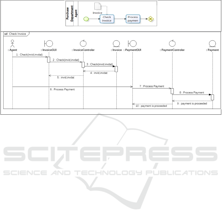
R9. If the name of the task is
«CommunicationVerb + BusinessObject + [[to
ReceiverName(s)] | [from SenderName]] », then
generate a design sequence diagram by following
these steps:
a. Add two lifelines representing respectively
instances of the “BusinessObjectControler”,
“BusinessObjectGUI”, and the sender, if they
aren’t already created. If the receiver noun is
singular (respectively plural), add also a lifeline
representing an instance of the receiver
(respectively, a multi-instance of the receiver)
b. If the task type is “send task” then, add a
asynchronous message between the instance of
Sender actor and the “BusinessObjectGUI”, as
well as a synchronous message from the
“BusinessObjectControler”, to an instance (See
Figure 4) or a multi-instance of Receiver. The
message is represented by the
CommunicationVerb() method which has three
arguments: “bo” instance of BusinessObject, “r”
(respectively, “r[]”) instance of the receiver
actor (respectively, an array of instance of all
receiver actors) and “s” instance of the actor
who sends “bo”. Finally, add a response
message from the instance or multi-instance of
Receiver to the
“BusinessObjectControler”called
BusinessObjectIsReceived. Add also a message
having the same name from the
“BusinessObjectControler” to the
“BusinessObjectGUI”. We recall that the
information related to receiver can be found
either in the activity business context or label.
If the task type is “receive task” then add an
asynchronous message called send() from the sender
to the “BusinessObjectGUI” and a synchronous
message called send() from the “BusinessObjectGUI”
to “BusinessObjectControler” and from the
“BusinessObjectControler” to the instance of
Receiver. The method has three arguments: “bo”
instance of BusinessObject, “r” instance of the
receiver actor, and “s” instance of the sender actor.
Add a response message from the instance of
Receiver to the “BusinessObjectControler” and from
the “BusinessObjectControler” to the
“BusinessObjectGUI” called
BusinessObjectIsReceived.
BPMN model
DSD
Figure 4: R9 illustration.
From BPMN Model to Design Sequence Diagrams
581
BPMN model
DSD
Figure 5: R10 illustration.
R10: For each fragment F in the BPMN model P:
if the fragment is composed of a set of activities
that belong to the same lane, then (see Figure 5):
a. Add asynchronous messages from the
agent to the “BusinessObjectGUI”, from
the “BusinessObjectGUI” to the
“BusinessObjectControler”
Add a synchronous message from the
“BusinessObjectControler” to the
“BusinessObjectEntity”. These messages have the
name of “ActionVerb”. Next, add a response
message from the “BusinessObjetEntity” to the
“BusinessObjectControler” and from
the“BusinessObjectControler” to the
“BusinessObjetEntity”R11: Each fragment F
composed of only one activity labeled with
R11.1: “Send x” or “Send x to y”, its
corresponding DSD will be named “Generate x”;
R11.2: “Receive x” or “Receive x from y”, its
corresponding DSD will be named “Manage x”; we
note that the information related to the sender can
be found in the business context of the activity.
R11.3: If the first activity SA of a fragment F is
labeled “Create x“, then the corresponding use case
UC_F will be named “Manage x”.
R12: For each gateway in the BPMN model P,
add:
a. An interaction operator Par with a combined
frame if the gateway is parallel. Each Par
frame has as many operands to the outgoing
flows of the parallel gateway.
b. An Alt frame if the gateway is an exclusive or
inclusive one. Each Alt frame has as many
operands to the outgoing flows of the
exclusive/inclusive gateway. We note that
when an outgoing flow contains only an end
node, it will not be calculated. If the number
of operands is equal one, then change Alt
frame to Opt frame. In all cases, the outgoing
message label is used to define the guard of
each operand.
c. a loop combined fragment corresponding to
each gateway with one of the outgoing
sequence flow is a precedent activity in the
BPMN model.
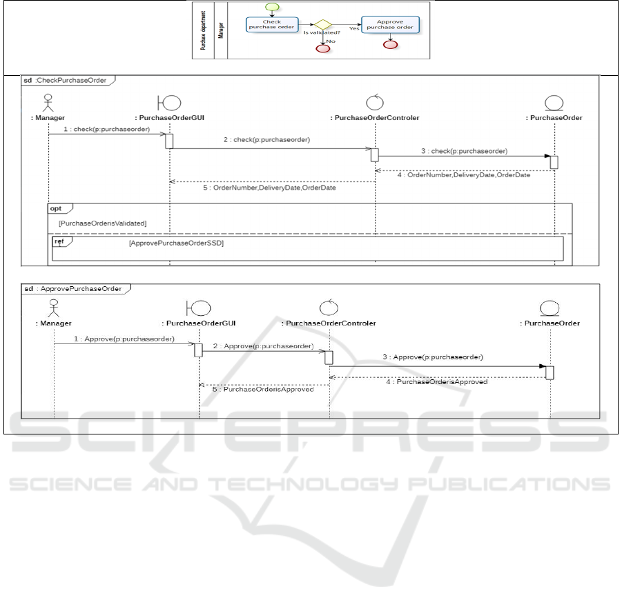
R13: For each gateway between two fragments PF
(entry) and NF (exit) such that the activities of both
fragments are in the same lane : Apply first R8 on
each BPMN fragment to derive the DSD, if they are
not already generated. Then, enhance the DSD
corresponding by applying R12. The latter adds an
Opt frame that includes another frame Ref to the
DSD corresponding to NF (exit) (see Figure 6).
ICEIS 2022 - 24th International Conference on Enterprise Information Systems
582
BPMN model
DSD
Figure 6: R13 illustration.
4 DESTINY TOOL AND
EVALUATION
To facilitate the application of our method, we have
developed a tool for assessing the alignment between
BPMN model and the corresponding design sequence
diagrams.
Our tool is implemented as an EclipseTM plug-in
(Eclipse, 2013). It is composed of two main modules:
the generator module and the evaluator module. The
“Behavioral diagrams generator” takes a business
process modeled by BIZAGI tool (ISO/IEC 19510,
2013). Then, we transform it into XPDL file (Shapiro,
2008). Based on the generated file, the information
extracted by the extractor reflects the business
context. The latter describes each BPMN element by
a set of features. Figure 7 shows the BPMN example
“Purchase order” which is annotated according to the
renaming linguistic patterns.
Next, we tagged each pool/lane with the
stereotypes (Rumbaugh and Jacobson, 2005):
business actor and business worker. The “Manager”
and “Agent” are considered as business worker, while
the supplier is a business actor. Recall that a business
worker represents an abstraction of a human that acts
within the business to realize a service, while a
business actor represents a role played by some
person or system external to the modeled business
and interacting with the business. So that, the
activities of “supplier” pool are out of the system
scope and are ignored in the generation of the design
sequence diagrams.
Secondly, we decomposed the BPMN model on a
set of five fragments F: F1, F2, F3, F4 and F5 (See
Figure 7).
F1 is decomposed into three sub-Fragments: F1.1,
F1.2 and F1.3. The first one F1.1 “Receive purchase
request”, the second one F1.2 contains the sub-
process “Quotations”, and the third one F1.3
contains two activities which are “Create purchase
order” and “Approve purchase order”. F2, F3 and F4
are expressed respectively by “Send purchase order”,
“Receive invoice” and “Receive item” activities. F5
includes “Process payment” and “Notify payment”
activities.
From BPMN Model to Design Sequence Diagrams
583
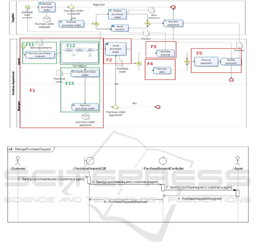
Figure 7: Purchase order Business Process in BPMN (ISO/IEC 19510, 2013).
Figure 8: ManagePurchaseRequestDSD.
To illustrate the application of our transformation
rules, we apply R2.1 that transforms the pool
“Purchase Department” containing the business
workers to a set of lifelines and an activation zone
representing GUI, entities and control classes that
belong to the system perimeter. Each pool’s lane that
represents the business workers “Agent” and
“Manager” is transformed to an actor by applying R3.
The business actor “Supplier” is transformed into a
secondary actor by applying R3.
The fragment F1.1 includes only one activity
which is “ReceivePurchaseRequest”. By applying
R11.2, we generate the design sequence diagram
called “ManagePurchaseRequest”. To describe the
behaviour of this design sequence diagram, we first
apply R3 to generate a lifeline for each actor. Finally,
we invoke R9.c that transforms the task “Receive
purchase request” to asynchronous messages called
send (from the “Customer” to the
“PurhaseRequestGUI” and from
“PurhaseRequestGUI” to the
“PurhaseRequestControler”. A synchronous message
is then added from the “PurhaseRequestControler”
to the “Agent” which represents the receiver instance.
The method has three arguments: “pr” instance of
“PurchaseRequest”, “a” instance of the receiver actor
“agent”, and “c” instance of the sender actor
“customer”. Then, the rule adds a response message
from the instance of Receiver to the
“PurhaseRequestControler” and from the latter to the
“PurhaseRequestGUI” called
“PurchaseRequestIsReceived” (See Figure 8).
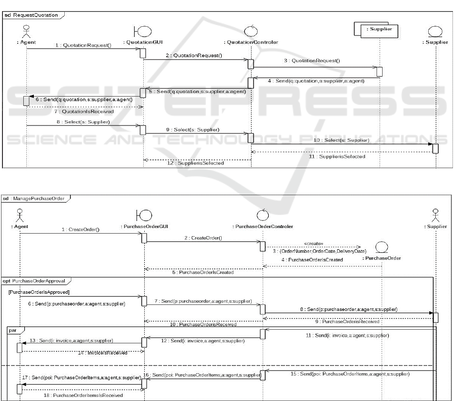
The fragment F1.2 includes the “Quotation” sub
process which is composed of a set of sequential tasks
“Request quotations”, “Receive quotations” and
“Select supplier”. The structure of this sub-process
ICEIS 2022 - 24th International Conference on Enterprise Information Systems
584
doesn’t call for applying again the fragmentation
process.
By applying R8.1 on each activity of the
fragment, we first generate a synchronous message
from the agent to the “QuotationGUI”, and then from
the “QuotationGUI” to the “QuotationControler”.
Next, an asynchronous message
“Quotationrequest()” is send from the
QuotationControler” to a multi instance “suppliers”.
The activity “Receive quotations” introduces the
lifeline corresponding to the multi-instance of
suppliers. This is inferred from the business context
of the activity. By applying R9.c, we add an
asynchronous message send() from the multi-instance
supplier lifeline to the “QuotationControler” and
from the latter to the “QuotationGUI”. Then, we add
a synchronous message called send() from the
“QuotationGUI” to the receiver instance: “agent”.
Both of them have the same arguments: “q” instance
of the business object “quotation”, “a” instance of the
agent who receives “q”, and “s” instance of the
supplier who sends “q”. We add a response message
from the “Agent” to the “QuotationGUI” called
QuotationIsReceived.
Finally, by applying R8.1, the transformation of
the activity “Select supplier” adds a new lifeline “s”
instance of “Supplier” and a message called “select(s:
Supplier)” from the agent to the “QuotationGUI” and
from the latter to the “QuotationControler” The
business context of the activity reveals that the
supplier must be notified by the agent decision. This
leads to add a synchronous message from the
“QuotationControler” to the supplier. The rule adds a
response message, called “SupplierIsSelected”, from
the instance of Receiver to the“QuotationControler”,
and from the latter to the “QuotationGUI” (See
Figure 9).
Figure 9: RequestQuotationsDSD.
Figure 10: ManagePurchaseOrderDSD.
From BPMN Model to Design Sequence Diagrams
585
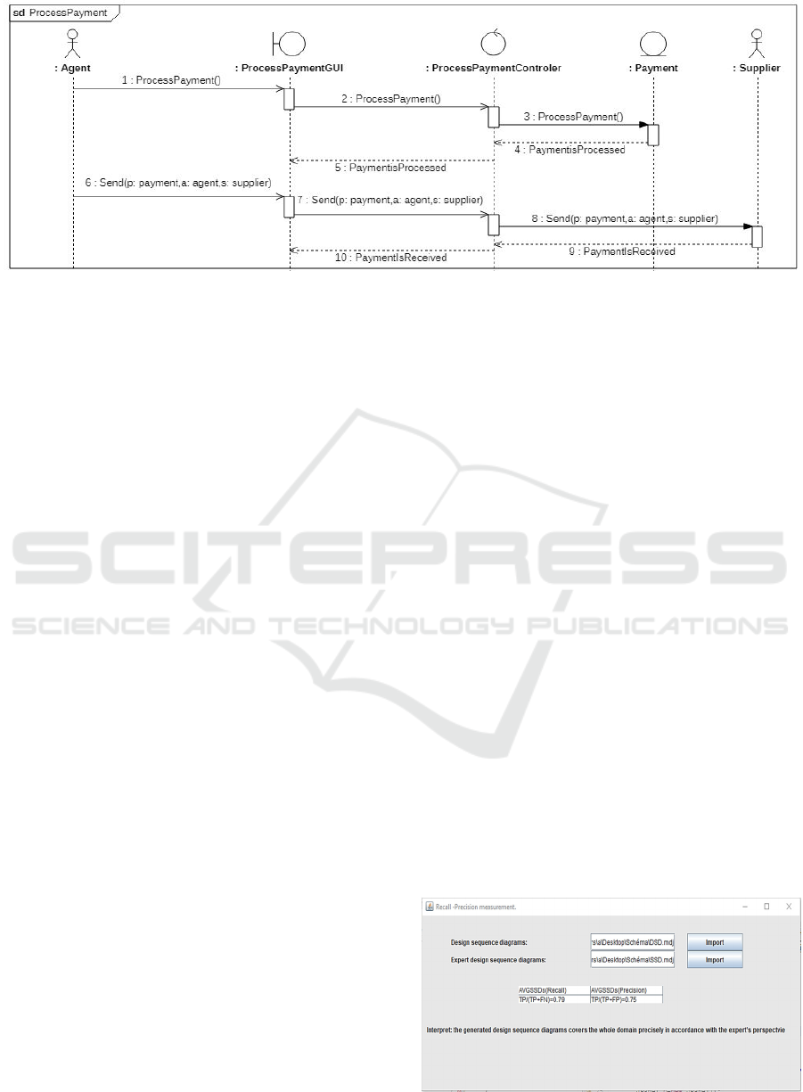
Figure 11: ProcessPaymentDSD.
The fragment F1.3 includes two activities which
are “Create purchase order” and “Approve purchase
order”. Based on R11.3, the name of the fragment
will be “Manage Purchase Order”.
The design sequence diagram that describes the
behavior of the fragment “Manage Purchase Order”
(See Figure 10) is obtained by applying R8.1 and
R12. According to R8.1, the first activities of the
fragment generate an asynchronous messages from
the agent corresponding to the lane, which is already
generated by R3, to the “PurchaseOrderGUI”. Next,
we add a new asynchrous message having the name
CreateOrder(), from the “PurchaseOrderGUI” to the
“PurchaseOrderControler”. A synchronous message
having the same name is then added from the
“PurchaseOrderControler” to the
“PurchaseOrderEntity”. A response message from the
“PurchaseOrderEntity” pointing back to the original
lifeline is added. The response label is a
concatenation between the BusinessObject
“PurchaseOrder” and the passive voice of the
ActionVerb “create”.
Then, we add a synchronous message
“approve(p:purchaseOrder)”. We note that the
parameters are extracted from the business context of
the corresponding activities. The exclusive gateway
calls to apply R12.b. The latter generates an Opt
frame called “PurchaseOrderApproval” that contains
1) a sequence of messages derived by applying R9.b
on the activity “Send Purchase Order (s: supplier)”,
2) a Par frame that contains two operands. Each one
of them models the behaviour of “Receive Invoice”
and “Receive Item” (See Figure 10). This is obtained
by applying R12.a and R9.c.
The fragment F5 generates “Process Payment”.
Its design sequence diagram (See Figure 11) is
obtained by applying R8.1 and R9.b.
The “generator” applies the transformation rules to
derive design sequence diagram corresponding to
each fragment.
To validate the transformation rules, the evaluator
examines experimentally the performance of the
transformations through the calculation of recall and
precision rates. It uses them to compare the models
generated by our method to those supplied by the
expert. For each element type of the design sequence
diagram DSD (object, message, parameters, etc.), the
recall and precision rates are calculated according the
following equations:
Precision = TP/(TP+FP)
(1)
Recall = TP/(TP+FN)
(2)
Where:
• True positive (TP) is the number of existing
real elements generated by our transformation;
• False Positive (FP) is the number of not
existing real elements generated by our
transformation;
• False Negative (FN) is the number of existing
real elements not generated.
In fact, for the design sequence diagrams, the
evaluator calculates the average (AVGSSDs) of recall
and precision rates (See Figure 12).
Figure 12: Recall and precision measurement.
ICEIS 2022 - 24th International Conference on Enterprise Information Systems
586
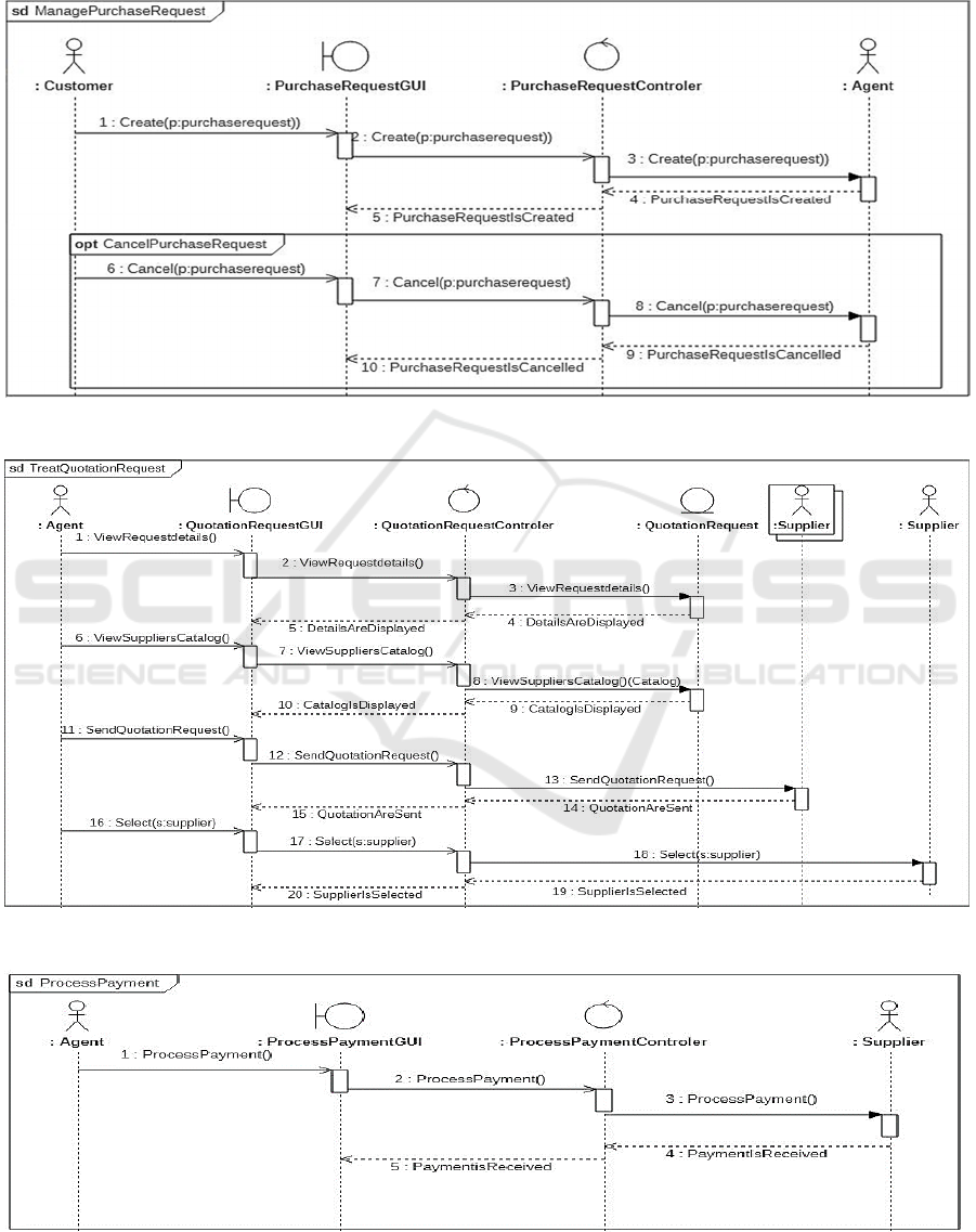
The high scores for both ratios mean that the
generated UML diagrams cover the whole domain
precisely in accordance with the experts perspective
(See Figures 13, 14, 15, 16). We can deduce that the
performance of our method approaches the human
performance.
Figure 13: ManagePurchaseRequestsDSD.
Figure 14: TreatQuotationRequestsDSD.
Figure 15: ProcessPaymentDSD.
From BPMN Model to Design Sequence Diagrams
587
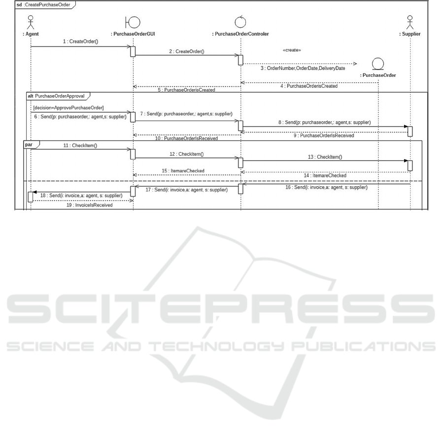
Figure 16: ManagePurchaseOrdersDSD.
5 CONCLUSIONS
This paper proposed a transformation-based
approach to generate design sequence diagrams
from business process models. It provides for the
generation of objects and their relations that are
aligned to the business logic. Compared to existing
works, our approach has the merit of accounting for
both the semantic and structural aspects of the
business process model. In addition, the proposed
rules are implemented in a tool for generating
design sequence diagrams. The produced diagrams
are evaluated based on empirical experimentation.
REFERENCES
Aversano, L., Grasso., C., Tortorella, M., 2016. Managing
the alignment between business processes and
software systems. In journal information and
software technology, v.7 (3). pp. 171-188.
Berrocal, J., Garcıa-Alonso, J., Vicente-Chicote, C. &
Murillo, J. M., 2014. A Pattern-Based and Model-
Driven Approach for Deriving IT System Functional
Models from Annotated Business Models. In
Information System Development, pp 319-332.
Bouzidi, A., Haddar, N. Z., Ben-Abdallah, M., Haddar,
K., 2020. From bpmn to sequence diagrams:
Transformation and traceability. In: ENASE, pp. 438-
445.
Eclipse, Available from: http://www.eclipse.org. (2013).
ISO/IEC 19510, 2013 ISO/IEC 19510. 2013. Information
technology -- Object Management Group Business
Process Model and Notation.
Khlif W., Ben Ayed N., Almogati E., Ben-Abdallah H.,
2018''Designing BP-IS aligned models: An MDA-
based Transformation Methodology''. In Inter. Conf.
on Evaluation of Novel approaches to software
engineering.
Rhazali, Y. Hadi, Y. Mouloudi, A., 2016. A Based-Rule
Method to Transform CIM to PIM into MDA. In
International Journal of Cloud Applications and
Computing, IJCAC., pp.11-24.
Rostami, K., Heinrich, R., Busch, A., Reussner, R. H,
2017. Architecture-Based Change Impact Analysis in
Information Systems and Business Processes. In
ICSA’17, Inter. Conf. on Software Architecture.
Rumbaugh, J., Jacobson, I., Booch, g., 2005. The Unified
Modeling Language Reference Manual, pp. 742.
Shapiro, R.M. XPDL 2.0 (2006). Integrating process
interchange and BPMN.
Suchenia, A., Kluza, K., Jobczyk, K., Wisniewski, P.,
Wypych, M., Ligeza, A., 2017. Supporting BPMN
Process Models with UML Sequence Diagrams for
Representing Time Issues and Testing Models. Pp.
589-598.
ICEIS 2022 - 24th International Conference on Enterprise Information Systems
588
