
ETAP Simulations of Adaptive Overcurrent Protection Scheme for
Distribution Network with Microgrids
Paul Jacob Palayil
1,2 a
, Ishan Desai
1,2 b
and Divyesh Mangroliya
1,2 c
1
Parul Institute of Engineering & Technology, Parul University, P.O. Limda, Vadodara, Gujarat, India
2
Department of Electrical Engineering, Faculty of Engineering and Technology, Parul University, India
ishan.desai@paruluniversity.ac.in, divyesh.mangroliya@paruluniversity.ac.in
Keywords: Microgrids, Distributed Generation, Adaptive over Current Protection, Protection Coordination, ETAP.
Abstract: A microgrid (MG) includes Distributed Energy Resources (DER), controllable load with adequate protection
scheme in an Electrical Power Distribution System. Renewable energy sources (RES) is expected to provide
efficient, low cost and clean energy with decentralized generation, storage and local consumption with MG.
In this paper an Adaptive Over Current Relays (AOCR) scheme in distribution networks (DN) considering
intermittency of Distributed Generation (DG) operations using a fuzzy logic controller (FLC) is proposed.
The onsite study included actual verification of protection scheme, the impact of DG on protection system
and protection coordination. A part of the IEEE 44 nodes radial distribution test feeder is taken for modelling
& simulating the proposed AOCR using Electrical Transient Analyzer Program (ETAP) software
environment.
1 INTRODUCTION
1.1 Background
Distributed generation can be defined as “small-scale
generating units located close to the loads that are
being served” [Nadarajah et.al, 2017]. Given the
business, regulatory and policy push, decreasing
product prices, the penetration level of DG will
consistently increase [Romero, 2017]. The benefits
shall include: network reliability & resilience,
reduction of grid congestion and peak loads, improve
the operation and stability of regional grids,
transmission loss & generation cost reduction,
postponement of investments in network expansion,
and lowering capital investment costs [Nascimento
et.al, 2016]. 3 types of microgrids are; remote, grid
connected and networked.
1.2 Challenges of MG Protection
Integrating DG causes the existing DN to lose its
radial power flow and traditional relay settings may
a
https://orcid.org/0000-0002-9972-1814
b
https://orcid.org/0000-0002-6955-5210
c
https://orcid.org/0000-0001-8525-4330
work incorrectly and become inadequate. Issues such
as: increase in short circuit level, bidirectional power
flow, voltage & frequency fluctuation etc. affect the
protective relays performance and power quality
issues [Bhise et.al, 2017]. Some of the consequences
are like false tripping, under and overreach, blinding
of relays and islanding [Tian et.al, 2016] require fast
& accurate OC and Earth fault Protective schemes.
1.3 Proposed Solution under Study
Several schemes have been introduced to alleviate the
impact of integrating DG in DNs [Saad et.al, 2017],
the best being adaptive protection scheme (APS). For
this project, an APS based on FLC is proposed
.
2 LITERATURE REVIEW
2.1 Power System Protection
“The objective of electrical system protection and
130
Palayil, P., Desai, I. and Mangroliya, D.
ETAP Simulations of Adaptive Overcurrent Protection Scheme for Distribution Network with Microgrids.
DOI: 10.5220/0011073700003203
In Proceedings of the 11th International Conference on Smart Cities and Green ICT Systems (SMARTGREENS 2022), pages 130-138
ISBN: 978-989-758-572-2; ISSN: 2184-4968
Copyright
c
2022 by SCITEPRESS – Science and Technology Publications, Lda. All rights reserved
coordination are to;
- Limit the extend and duration of service interruption
whenever equipment failure, human error or adverse
natural events occur on any portion of the system
-Minimize damage to the system components
involved in the failure” (IEEE 242-2001)
Rapid disconnection of faulted apparatus limits
the amount of damage to it and prevents the effects of
fault from spreading into the system (Juan et.al,
2011). It can be classified into apparatus protection
and system protection. ANSI numbers, according to
their functions also classifies them.
2.2 Over Current and Earth Fault
Relays
Overcurrent relays are classified as follow:
1. Instantaneous Overcurrent Relays:
2. Definite Time Overcurrent Relays:
3. Inverse Time Overcurrent Relays (IDMT):
There are several types of inverse-time curves, which
are mathematically modeled under the IEC,
ANSI/IEEE standards and manufacturer policies as;
𝑡
𝑇𝑀𝑆 𝛽
𝐼
𝐼
𝑠
𝛼
1
𝐿
(1)
where: t is the operating time in seconds,
I is the fault current level at the secondary side of
current transformer,
I
s
is the current setting expressed at the secondary side
of current transformer
L, α, β, are constants are as in Table 1.
Table 1: IEC Constants.
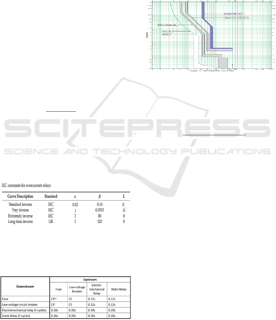
Time Current Characteristics (TCC)- “Selectively
coordinated” back up relay will wait for primary
devices “should” sense, operate and clear the fault.
BuffBook(IEEE242‐2001)‐MinimumCTIs
a
Table 2: Minimum CTI’s.
a
Relay settings assumed to be field-tested and calibrated.
b
CS – Clear space between curves with upstream minimum-
melting curve adjusted for pre-load.
c
Some manufacturers may also recommend a safety factor.
Consult manufacturers’ time-current curves.
4. Directional Overcurrent Relays (DOCR): Three
conditions must be satisfied for its operation: current
magnitude, time delay and directionality (Bayliss
et.al, 2007).
Figure 1: TCC.
2.3 Setting of over Current Relays
Based on system requirements, the pickup current of
the relay is adjusted by plug bridge for required
number of tapping in the coil with equation:
𝐶𝑢𝑟𝑟𝑒𝑛𝑡 𝑆𝑒𝑡𝑡𝑖𝑛𝑔
𝑃𝑖𝑐𝑘𝑢𝑝 𝐶𝑢𝑟𝑟𝑒𝑛𝑡
𝑅𝑎𝑡𝑡𝑒𝑑 𝑆𝑒𝑐𝑜𝑛𝑑𝑎𝑟𝑦 𝐶𝑢𝑟𝑟𝑒𝑛𝑡 𝑜𝑓 𝐶𝑇
100%
(2)
2.4 Coordination of Overcurrent
Relays
Selective coordination of protective devices needed
so that the fundamental protective functions are met
under the required attributes of protective relaying,
which are sensitivity, selectivity, reliability, and
speed (Ibrahim et.al, 2016).
In numerical relays there is no overrun, and
therefore the CTI can be as low as 0.2 s (Shih et.al,
2016).
Unlike the Over Current Relays, the Earth Fault
relays do not respond to the 3 phase or L-L Faults.
One earth fault relay is adequate to provide protection
for all types of earth faults. To provide sensitive
protection, it use zero sequence current and it is
mandatory to keep the pick-up current (min 15%)
above the maximum unbalance factor of 10%. To do
setting and coordination, only L-G faults are
considered.
Logic Coordination methods uses modern relays and
fast communication channels, the relay setting and
coordination involves primarily following steps:
ETAP Simulations of Adaptive Overcurrent Protection Scheme for Distribution Network with Microgrids
131

Figure 2: Logic coordination.
a) Identify all possible primary-backup relay pairs.
b) Decide the correct sequence of relay coordination.
c) Decide the pickup value and hence PSM for
relays.
d) Compute the TMS to meet the coordination.
e) Validation of the results.
2.5 Steps for Coordination Study
A) Develop a SLD of the system under study.
B) Determine normal, emergency and temporary
operating configurations of the system
C) Carry out the load flow analysis to determine the
minimum pick up settings of various devices
D) Carry out the short circuit analysis to determine;
1.Maximum and Minimum momentary single phase
and 3 phase short circuit currents
2. Maximum and Minimum interrupting duty 3 phase
short circuit currents
3. Maximum and Minimum ground fault currents
E) Collect the characteristics of the devices: TCC
curves & settings range from manufacturers.
F) Collect the thermal limit curves for devices
G) Determine the range of adjustments on the settings
of upstream or downstream overcurrent relays.
2.6 Impact of DG Integration on
Protection Coordination
MG changes the original DN topology, fault current
& bidirectional flow of currents depends on fault
location, capacity and number of DGs.
False Tripping and Loss of Coordination.
The definition of protection coordination loss can
be taken as “violation of CTI constraint between the
primary and backup relays” (Shih et.al, 2017).
Protection Blinding. Also known as protection
under- reach since the actual reach of the feeder relay
is decreased due to fault current contribution from the
DG (Korres et.al, 2016).
Nuisance Tripping of Feeder.
Islanding Operation.
2.7 Adaptive Protection Coordination
Scheme
In APS, continuous monitoring of operational and
topological changes of the network is ensured.
Communication has a major role in an adaptive
relaying (Wan et.al, 2010). Modern relays can switch
between multiple groups of time current characteristic
curves based on the system operating conditions. The
non-communication based APS relays respond
immediately based on pre-calculated settings
configured in it against different DN network
topology.
2.8 Fuzzy Logic Control
It provides an inference structure as means for
converting linguistic strategy into control actions and
thus offers a high-level computation (Sivanandan
et.al, 2007). FLC belongs to the class of “intelligent
control,” which uses knowledge-based decision-
making employing techniques of fuzzy logic (Karray
et.al, 2004) for the control actions.
There are three commonly used types of fuzzy
system (Altas, 2017),
a) Mamdani fuzzy system
b) Takagi-Sugeno (TKS) fuzzy system
c) Tsukamoto fuzzy system
A zero-order Sugeno fuzzy model is functionally
equivalent to a radial basis function network under
certain minor constraints.
The use of FLC has increased rapidly in power
systems for load/frequency control, bus bar voltage
regulation, stability, load estimation, power flow
analysis, parameter estimation, protection systems
and many other fields.
2.9 Review on Techniques Used to
Mitigate the Impact of DG
Penetration on Protection Relays
Coordination
Various solutions proposed are;
Disconnecting the DGs immediately after fault
detection by S. Conti, 2009
Limiting the capacity of installed DGs
(Chaitusaney et.al, 2008)
Modifying the protection system by installing
non-communication-based approach by adding more
protective devices like multi-function devices &
reclosers (Hamed Funmilayo and K. L. Butler-Purry,
2009).
Installing the fault current limiters (FCLs) to
SMARTGREENS 2022 - 11th International Conference on Smart Cities and Green ICT Systems
132
preserve or restore the original relay settings (Kim &
Elmitwally et.al, 2016).
Employing fault ride through control strategy of
inverter based DGs (Naderi et.al, 2017)
To avoid miscoordination of IDMT relays for
synchronous-DG, W. Xu et.al, 2014 used a solid-
state-switch-based field discharge circuit to limit the
generator’s fault current.
Abbas Esmaeili et.al. 2016 used optimal
programming of fault current limiters using two-stage
stochastic model.
E. Ebrahimi et al, 2014 used fault ride through
approach for IBDG; Control strategy was proposed
and applied to the voltage source converter (VSC) so
that the protection coordination remains unchanged.
R. Sitharthan et.al, 2016 used an APS for MG by
utilizing microprocessor-based over current relays.
They also used auto reclosers, through which the
proposed APS recovers faster from the fault and
increase the consistency of the MG as result.
Rahmati and Dimassi, 2014 proposed an APS
that uses a least square algorithm to determine the
Thevenin circuit equivalent using local
measurements in off-line information regarding
varying short-circuit levels caused by DER infeed.
APS using differential evolution algorithm (DE)
on DOCR & ABC algorithm coordination used
automatic online re-adjustment of settings for
different MG topologies results from dispatch or
natural conditions.
Data mining and analytics or “Big Data” can play
a vital role in modern MG. Main areas of
Computational Intelligence (CI) methods, ANN’s,
PSO algorithms etc. can be used for AP Solutions.
FLCs allows larger solution space and find
applications in areas that derive inferences from
uncertain and undefined data of renewable energy
based DGs (Sampath, 2015).
3 METHODOLOGY
3.1 APS based on Pre-calculated
Settings
The AOCR can be programmed for simulation with
Automatic setting groups (SG) design. By auto
selecting the mode of operations, with proper
protection and restoration control logic the MG
switchgears can be controlled automatically. Through
the Etap- real time, all necessary inputs for the event
table of all relay pairs matching the mode of operation
and the location of the fault can be made.
The IEC standard inverse characteristic equation
3 of overcurrent relay (Juan et.al,2011) to use;
𝑡
0.14 𝑇𝑀𝑆
𝐼
𝐼
.
1
(3)
Where: TMS is the time multiplier setting of the relay,
I
f
is the fault current seen by the relay, I
pickup
is the
pickup current of the relay. TMS and I
pickup
should be
determined in a special range as follows:
𝑇𝑀𝑆
min
≤𝑇𝑀𝑆≤𝑇𝑀𝑆
max
I
pickup min
≤𝐼𝑃≤ I
pickup max
To ensure the selectivity, the operating time of
Backup Relays (𝑡
𝑏
) should have enough delay time
from Primary relays (𝑡
𝑝
) as CTI:
𝑡
𝑏
−𝑡
𝑝
≥𝐶𝑇𝐼
3.2 APS based on Real Time
Calculated Settings
Adaptive protection is “an online activity that
modifies the preferred protective response to a change
in system conditions or requirements in a timely
manner by means of externally generated signals or
control action” (Rockefeller, 1988). The required
settings are updated in online manner as per variation
in fault current levels seen by relays during changing
network conditions (IEEE, 2014).
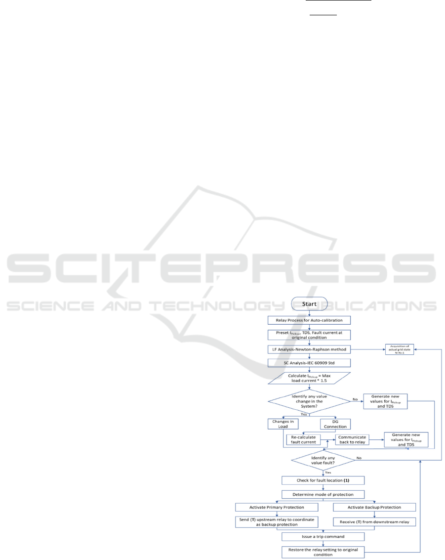
Figure 3: Flow chart of the proposed AOCR for MG.
ETAP Simulations of Adaptive Overcurrent Protection Scheme for Distribution Network with Microgrids
133
The adaptive relay connected to the network will
firstly do an auto-calibrate. After that, the parameters
of I
pickup
, Time Dial Setting (TDS) and the fault
current will be preset to zero. Following, it will do a
Newton–Raphson method of load flow analysis &
Short Circuit Analysis by IEC 60909 Std. Then, it will
calculate the I
pickup
with required (1.5 times for
example) safety margin (Sung et.al, 2013). However,
if there is a change in configuration i.e. DG
connections, the same is
communicated
through the
relay which results in a new set of parameters for
I
pickup
and TDS.
The next step is identifying the fault and its
location by using the overcurrent equation, which is
denoted by “(1)” in the algorithm. The principle of
overcurrent protection is shown;
I
j
> I
pickup
(4)
In the overcurrent principle, the “Normal Condition”,
where there is no fault, relay will not trip circuit
breakers (CB). “(T)” is the representation of the
second condition, which is the short-circuit or fault
condition. When I
j
is greater the I
pickup
, after
determining the mode of protection, it issues a
command for the right CB to trip. Once the fault is
cleared, it will restore to the original condition. It
continues to do the same process for the next iteration
where N = N + 1.
3.3 APS Algorithm in the Distribution
Network
The above flow chart can be coded in Fuzzy logic
controller for real time use. With SCADA, the Fuzzy
Logic Designer application for Microgrid Central
Controller (MGCC) makes the IED’s completely
adaptive. The application needs the power network’s
model for load flow calculation as well as
measurement integration for collecting online data by
using communication protocols. Real-time simulation
uses the execution of new solutions in monitoring, the
control system, and automation.
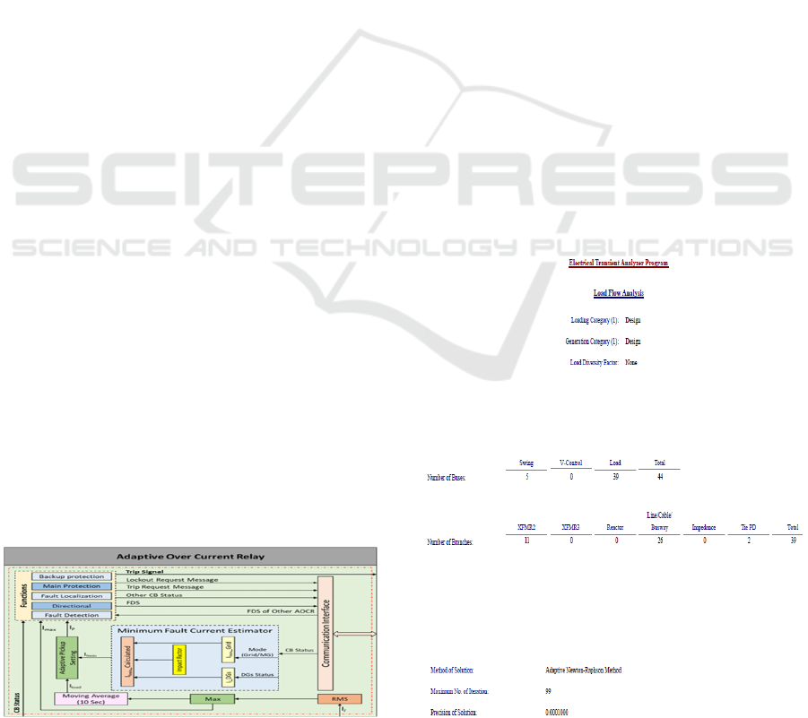
3.4 AOCR Block Diagram
Figure 4: AOCR block diagram.
4 SIMULATIONS SET UP
4.1 Site Data
In this study, the IEEE 44 bus radial feeder existing
DN is adopted. ETAP software (Etap 21.0.1 version)
is used to draw the detailed SLD, simulate the LFA,
SC & CTI studies. Relays like SE P122/ P139, Tr -
O/C & E/F, busbar/ feeder management protection, all
existing Switchgears and devices were site verified.
Numbering of buses and sources done, the master
SLD finalized before create a site SLD for the
simulations. All required permits, tools, methodology
secured, on-site verifications assisted by an expert.
4.2 Description of ETAP Simulation
Set Up
All required analysis was performed in a personal
computer with an Etap dongle and in the 9-bus
subnetwork (MG model). The new feature in the
SCADA system is the state estimation concept which
is used by the ETAP real-time application. It supports
the advancement of the information and automation
schemes for autonomous protections.
SGs features were identified with the help of Etap
simulations as per Figure 4.2 with 2 DG’s for 4 loads
connected to “Chiller bus 7” which is designed as the
emergency backup chillers to cater the critical loads.
Figure 5: Summary DN data.
SMARTGREENS 2022 - 11th International Conference on Smart Cities and Green ICT Systems
134
5 ETAP SIMULATION RESULTS
VERIFIED OF SELECTED IEEE-
9 BUS SUBSYSTEM
5.1 Load Flow Analysis Reports
5.1.1 LFA by Adaptive Newton Raphson
Method
Figure 6: LFA.
5.1.2 LFA Report Summary of Generation,
Load and Demand
Table 3: LFA.
Description MW MVar MVA %PF
Total Demand-
Source
(
Swin
g)
2.97 1.80 3.48 85.6Lag
Total Motor Load
2.38 1.47 2.80 85.0Lag
Total static Load
0.59 0.37 0.70 85.0Lag
Apparent Loss
0.003 -0.041
System Mismatch
0 0
No. of iterations 01
5.2 Short Circuit Analysis Reports
SCA by IEC 60909 Standard of selected network
carried out, for simplicity we have taken the reading
of 3 phase faults. With different SG’s the values of
Fault Current (KA) are found to be different and is
tabulated in Table 4.
5.3 Protection Coordination
Simulations
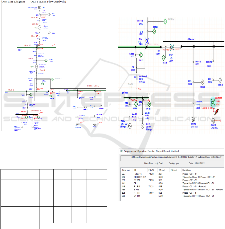
CTI Simulation with Fault Creation -Grid mode
(Curve settings verifications by ETAP 21.0.1 software
(Star Coordination option). The response sequence to
the fault simulation for SG #1 was given below.
Figure 7: SG 1 Fault simulation- relays response Sequence.
Figure 8: SG 1Fault simulation - relays response Report.
For each simulations the curve settings reviewed and
corrected for sequence and t
op
. A standard inverse
IEC curve is used to carry out the automatic
coordination of overcurrent protections (IEC & IEEE,
2009). Figure 9 below shows the CTI of relays
operation with Fault Simulation with SG #3 (PG +
2DG’s).
ETAP Simulations of Adaptive Overcurrent Protection Scheme for Distribution Network with Microgrids
135
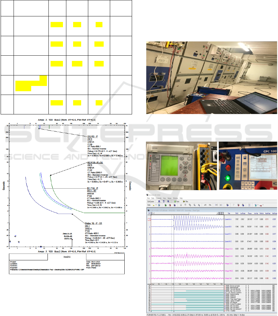
With different SG’s the values at which the relays
tripped are found to be different and the obtained
information tabulated as Table 4. The highlighted
values set in the same relay with the same fault but in
different configuration of sources clearly
demonstrates the needs for APS.
Table 4: CTI Report Summary.
SG #
SG
Configuration
Relay
Pair
Fault
Current
(KA)
I
pickup (A)
T1 in ms
1 PG Source only
R 16-
R2F18
R1F18
7.83
184
790
784
0.1
0.12
0.15
2 PG+ 1DG
R 16-
R2F18
R1F18
9.31
184
1100
784
0.1
0.12
0.15
3 PG+ 2DG
R 16-
R2F18
R1F18
10.89
184
1540
784
0.1
0.12
0.15
Island- 1DG (not
used for AOCR
settings)
R 16-
R2F18
DGR3
1.48
184
320
312
0.1
0.12
0.14
4 Island - 2DG
R 16-
R2F18
DGR3
3.06
184
620
620
0.1
0.12
0.14
Figure 9: SG 3 CTI of relays response Sequence.
From different analysis done for combinations of
power sources with its optimum curve settings of
relay pairs the input values for relay programming
established. The relay R2F18 selected being common
to all SGs for the adaptive settings.
6 AOCR FUNCTIONAL
VERIFICATION
We used SE P139 relay, 4 Automatic Settings Groups
programmed with Pre-Calculated values of pick up
and Time dial derived from Fault Simulations and
CTI settings respectively. The Relay PLC
programming (Easergy Studio V9.3.1-SE) also
defined the relay pairs for CB’s control actions. The
existing DN panels were set up for HIL tests by
secondary injection method. The relay test block
wired properly, connected the Omicron CPC 100 test
kit and relay control established through ethernet.
Figure 10: HIL Set up.
The results of L-L SC simulation results recorded as;
Figure 11: AOCR L-L Fault Simulation.
SMARTGREENS 2022 - 11th International Conference on Smart Cities and Green ICT Systems
136
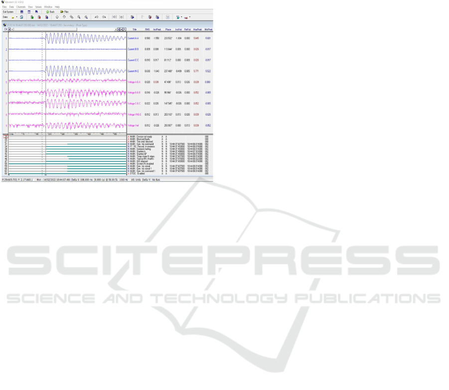
Detailed system generated reports like File
Information, Analog Summary, Events/Sensors
Activity Log and Summary downloaded.
Also, results of L-E Fault response graph recorded as;
Figure 12: AOCR L-E Fault Simulation.
7 CONCLUSION AND FUTURE
SCOPE
The adaptiveness of the relay functions verified
against programmed values. An algorithm has been
proposed for the AOCR to implement in Microgrids
with SCADA and Etap real time. Since IEC-61850
supplies appropriate peer-to-peer connection between
distributed IEDs, by using ‘generic object-oriented
substation events’ (GOOSE) technology, we may
achieve any data transmission through the network
within 4ms, so this protocol is being used in all
modern grids DNs [Tian et.al, 2016]. AOCR with
technologies such as AI and IoT, which uses real-time
values expected to have widespread use in future MG.
ACKNOWLEDGMENT
My sincere thanks to Er. Dhafi Rashid Al Marri, ED-
Engineering, HMC, Doha, Qatar for his guidance.
REFERENCES
Sung, B.C.; Lee, S.H.; Park, J.; Meliopoulos, A.P.S.
Algorithm for Overcurrent Relay in DS with DG. J.
Electr. Eng. Technol. 2013, 8, 1002–1011.
G. Juan M and E. J. Holmes, Protection of Electricity DNs
3rd Edition, London, UK: The Institution of
Engineering and Technology, 2011.
IEC. IEC 60255-151:2009 Measuring Relays and
Protection Equipment—Part 151: Functional
Requirements for over/under Current
M. Nadarajah, H. D. Quoc, and L. K. Y., Intelligent
Network Integration of Distributed Renewable
Generation. Springer Intl. Publishing AG, 2017.
IEEE. Std C37.112. for Inverse—Time Characteristics
Equations for OC Relays; IEEE: USA, 2018.
J. Romero, “Guest Editorial Special Section on Protection
and Real-Time Monitoring of T & D Systems with High
Penetration of DGs and Microgrids,” vol. 32, no. 1, pp.
333–334, 2017.
IEEE 1547 (2018), Std for interconnecting DER with EPS
J. P. Nascimento, N. S. D. Brito, and B. A. De Souza, “An
adaptive protection algorithm for DS with DG,” 2015
IEEE PES Innov. Smart Grid Technol. Lat. Am. ISGT
LATAM 2015, no. October 2015, pp. 165–170, 2016.
Tian, F., Wen, F., Wang, X., et al.: A multi-agent system
based fault diagnosis for active DS. IEEE Innovative
Smart Grid Technologies - Asia (ISGT-Asia)
Melbourne, VIC, Australia (2016).
S. M. Saad, N. El Naily, A. Elhaffar, K. El-Arroudi, and F.
A. Mohamed, “Applying APS to mitigate the impact of
DG on existing DN,” 2017 8th Int. Renew. Energy
Congr. IREC 2017, no. Irec, pp. 1–6, 2017.
C. R. Bayliss and B. J. Hardy, T & D Electrical
Engineering, Third edit. Elsevier Ltd, 2007.
M. Murali, P. S. Kumar, and K. Vijetha, “Adaptive
Relaying of Radial DS with Distributed Generation,”
Int. J. Electr. Comput. Eng., vol. 3, no. 3, 2013.
A. M. Ibrahim, W. Elkhatam, M. Mesallamy, and H. A.
Talaat, “Adaptive protection coordination scheme for
DN with DG using ABC,” J. Electr. Syst. Inf. Technol.,
vol. 3, no. 2, pp. 1–13, 2016.
M. Y. Shih, A. C. Enriquez, Z. M. Leonowicz, and L.
Martirano, “Mitigating the impact of DG on DOCR
relay coordination by APS,” EEEIC 2016 - Int. Conf.
Environ. Electr. Eng., pp. 1– 6, 2016.
G. Bizjak and G. Baruti, “Overcurrent protection,” in
Industrial Power System Protection, 2017, pp. 1–20.
D. R. Bhise, R. S. Kankale, and S. Jadhao, “Impact of DG
on Protection of Power System,” in International
Conference on Innovative Mechanisms for Industry
Applications (ICIMIA 2017), 2017, no. 1, pp. 399–405.
M. Y. Shih, A. Conde, Z. Leonowicz, and L. Martirano,
“An Adaptive OC Coordination Scheme to Improve
Relay Sensitivity and Overcome Drawbacks due to DG
in Smart Grids,” IEEE Trans. Ind. Appl., vol. 9994, no.
c, 2017.
N. H. V. Papaspilotopoulos, G. Korres, “An Adaptive
Protection Infrastructure for Modern Distribution Grids
with DG,” Cigre, no. February, pp. 125–132, 2016.
H. Wan, K. K. Li, and K. P. Wong, “An adaptive multiagent
approach to protection relay coordination with DGs in
industrial PDS,” IEEE Trans. Ind. Appl., vol. 46, no. 5,
pp. 2118–2124, 2010.
ETAP Simulations of Adaptive Overcurrent Protection Scheme for Distribution Network with Microgrids
137

S. N. Sivanandam, S. Sumathi, and S. N. Deepa,
Introduction to Fuzzy Logic using MATLAB. Springer,
2007.
F. O. Karray and C. De Silva, Soft Computing and
Intelligent Systems Design. Harlow: Pearson Education
Limited, 2004.
I. H. Altaş-, Fuzzy Logic Control in Energy Systems with
Design Applications in MATLAB Simulink-. IET, 2017.
S. Conti, “Analysis of distribution network protection
issues in presence of dispersed generation,” Electr.
Power Syst. Res., vol. 79, no. 1, pp. 49–56, 2009.
S. Chaitusaney and A. Yokoyama, “Prevention of reliability
degradation from recloser-fuse miscoordination due to
distributed generation,” IEEE Trans. Power Deliv., vol.
23, no. 4, pp. 2545–2554, 2008.
J. Chen, R. Fan, X. Duan, and J. Cao, “Penetration level
optimization for DG considering reliable action of relay
protection device constrains,” 1st Int. Conf. Sustain.
Power Gener. Supply, SUPERGEN ’09, vol. 430074,
pp. 1–5, 2009.
H. B. Funmilayo and K. L. Butler-Purry, “An approach to
mitigate the impact of distributed generation on the
overcurrent protection scheme for radial feeders,” 2009
IEEE/PES Power Syst. Conf. Expo. PSCE 2009, pp. 1–
11, 2009.
Y. Kim, H. C. Jo, and S. K. Joo, “Analysis of Impacts of
SFCL Placement on DG Expansion,” IEEE Trans.
Appl. Supercond., vol. 26, no. 4, 2016.
A. Esmaeili, S. Esmaeili, and H. Hojabri, “SC level control
through a multi-objective feeder reconfiguration using
FCLs in the presence of DGs,” IET Gener. Transm.
Distrib., vol. 10, no. 14, pp. 3458– 3469, 2016.
A. Elmitwally, E. Gouda, and S. Eladawy, “Optimal
allocation of FCLs for sustaining OC relays
coordination in a PS with distributed generation,”
Alexandria Eng. J., vol. 54, no. 4, pp. 1077–1089, 2015.
E. Ebrahimi, M. J. Sanjari, and G. B. Gharehpetian,
“Control of three-phase IBDGs during fault condition
without changing protection coordination,” Int. J.
Electr. Power Energy Syst., vol. 63, pp. 814–823, 2014.
S. B. Naderi, M. Negnevitsky, A. Jalilian, M. T. Hagh, and
K. M. Muttaqi, “Optimum resistive type FCL: An
efficient solution to achieve maximum fault ride-
through capability of fixed-speed wind turbines during
symmetrical and asymmetrical grid faults,” IEEE Trans.
Ind. Appl., vol. 53, no. 1, pp. 538–548, 2017.
H. Yazdanpanahi, S. Member, W. Xu, Y. W. Li, and S.
Member, “A Novel Fault Current Control Scheme to
Reduce Synchronous DG ’ s Impact on Protection
Coordination,” vol. 29, no. 2, pp. 542–551, 2014.
R. Sitharthan, M. Geethanjali, and T. Karpaga Senthil
Pandy, “Adaptive protection scheme for smart
microgrid with electronically coupled DGs,”
Alexandria Eng. J., vol. 55, no. 3, pp. 2539–2550, 2016.
A. Rahmati, M. A. Dimassi, R. Adhami, and D.
Bumblauskas, “An overcurrent protection relay based
on local measurements,” IEEE Trans. Ind. Appl., vol.
51, no. 3, pp. 2081–2085, 2014.
D. Sampath Kumar, S. Member, B. Menon Radhakrishnan,
D. Srinivasan, S. Member, and T. Reindl, “An Adaptive
Fuzzy based Relay for Protection of Distribution
Networks,” IEEE Int. Conf. Fuzzy Syst., pp. 1–5, 2015.
Rockefeller, G.D. et.al. (1988) Adaptive Relaying
Transmission Concepts for Improved Performance.
IEEE transactions on Power Delivery, 3 (4), 1446-
1458.
APPENDIX
Tools and Components Referred during
Study
1. MG Controllers
SEL- PowerMAX with RTAC, SEL 3555, 3560
and 651R
SE - Ecostructure Power, Micom P40 easergy
series
Opus 1 solutions – GridOS-DER EMS
GE – U90+ Multilin
2. Overcurrent protection devices for MG
Controllers
SE -P139/ GE -P14D/ Micom P446
Siemens - Siprotech/ Reyrolle 7SR/ ABB – REF
615
3. MG Simulation tools
EMTP & ETAP Realtime
MATLAB/Simulink -Java Agent Development
Environment
DigSilent/ Opal RT/ Siemens PSS/ DER –CAM
EPRI –OpenDSS/ GridLAB -D
4. Plug and Play type DER’s
Eaton - Heila Edge (Solar)
Cat BDP 250 (ESS invertor)
Alpha structure (Carlyle and SE)/ Bloom Energy
Siemens
5. Communication and compliance needs
IEEE 2030.7 & 8, IEC 61850 -9.2LE, Modbus,
RS232/485, IEEE 1547/242/C 37, IEC 61439 (LV)/
62271 (HV) for SWGR & Controls
6. Other Desirable Controller features
PLC compatibility, Load sharing/Shedding,
Voltage/frequency regulation, Power and PF
control, SER/Oscillography recorder, Short and
open circuit protection, Trip and close controls,
Self-diagnosis/self-calibrations
SMARTGREENS 2022 - 11th International Conference on Smart Cities and Green ICT Systems
138
