
Concept of Smart Infrastructure for Connected Vehicle Assist and Traffic
Flow Optimization
Shiva Agrawal
1,∗
, Rui Song
2,∗
, Akhil Kohli
3
, Andreas Korb
4
, Maximilian Andre
4
, Erik Holzinger
4
and Gordon Elger
1, 2
1
Institute for Innovative Mobility (IIMo), Technische Hochschule Ingolstadt, Germany
2
Fraunhofer IVI, Applied Center Connected Mobility and Infrastructure, Ingolstadt, Germany
3
EFS - Elektronische Fahrwerksysteme GmbH, Ingolstadt, Germany
4
eMundo GmbH Ingolstadt, Ingolstadt, Germany
{andreas.korb, maximilian.andre, erik.holzinger}@e-mundo.de
Keywords:
Road Side Unit (RSU), Smart Infrastructure, Radar, LiDAR, Camera, Perception, Sensor Data Fusion,
Vehicle-to-everything (V2X), Communication, Simulation, ITS.
Abstract:
The smart infrastructure units can play a vital role to develop smart cities of the future and in assisting auto-
mated vehicles on the road by providing extended perception and timely warnings to avoid accidents. This
paper focuses on the development of such an infrastructure unit, that is specifically designed for a pedestrian
crossing junction. It can control traffic lights at the junction by real-time environment perception through its
sensors and can optimize the flow of vehicles and passing vulnerable road users (VRUs). Moreover, it can
assist on-road vehicles by providing real-time information and critical warnings via a v2x module. This paper
further describes different use-cases of the work, all major hardware components involved in the development
of smart infrastructure unit, referred to as an edge, different sensor fusion approaches using the camera, radar,
and lidar mounted on the edge for environment perception, various modes of communication including v2x,
system design for backend and requirement for safety and security.
1 INTRODUCTION
The development of autonomous vehicles is currently
one of the biggest trends and challenges in the auto-
motive industry. In order to achieve the mission of
zero road accidents and to ease the journey of people,
a lot of companies around the world are investing both
money and time to develop advanced technology. One
of the important parts of autonomous vehicles is their
capability to perceive and predict other road users’
behavior and motion. This helps to predict the next
movement of the vehicle itself. For this purpose, such
vehicles are equipped with multiple sensors like cam-
eras, lidar, radar at different positions. The data from
each sensor is first individually processed and later
fused together to get an accurate environment view of
both static and dynamic surrounding objects.
Due to the complex structure of cities and the in-
crease of road users including vehicles and humans,
perception from the vehicle itself is not sufficient in
*The First Two Authors Contributed Equally.
many situations. In addition, it is also difficult for
the vehicle to get information about next danger situ-
ations, blocked or damaged roads, states of the traffic
light in next signals, passing of emergency vehicles,
etc. well ahead of the time without support from ex-
ternal sources.
One of the solutions to these issues can be the
development and deployment of smart infrastructure
units alongside the roads. Such units consist of multi-
ple sensors to perceive the environment and commu-
nication modules to provide helpful information and
timely warnings to vehicles on the road.
In recent years, project work to developed smart
infrastructure and connected mobility has started in
different regions as described in (RWTH Aachen
University - ika, ), (BW-test field, ), (providentia++, )
and (dai-labor TU Berlin, ). One of the projects to set
up a test field for smart infrastructure and connected
mobility is in development in Ingolstadt (Agrawal
and Elger, 2021). The work described in this paper
is well connected with this research project but with a
360
Agrawal, S., Song, R., Kohli, A., Korb, A., Andre, M., Holzinger, E. and Elger, G.
Concept of Smart Infrastructure for Connected Vehicle Assist and Traffic Flow Optimization.
DOI: 10.5220/0011068800003191
In Proceedings of the 8th International Conference on Vehicle Technology and Intelligent Transport Systems (VEHITS 2022), pages 360-367
ISBN: 978-989-758-573-9; ISSN: 2184-495X
Copyright
c
2022 by SCITEPRESS – Science and Technology Publications, Lda. All rights reserved
special focus to control the traffic lights on the pedes-
trian crossing junction to optimize the traffic flow in-
cluding vehicles and venerable road users (VRUs) as
highlighted in figure 1. Other use-cases of this work
are stated in a later section.
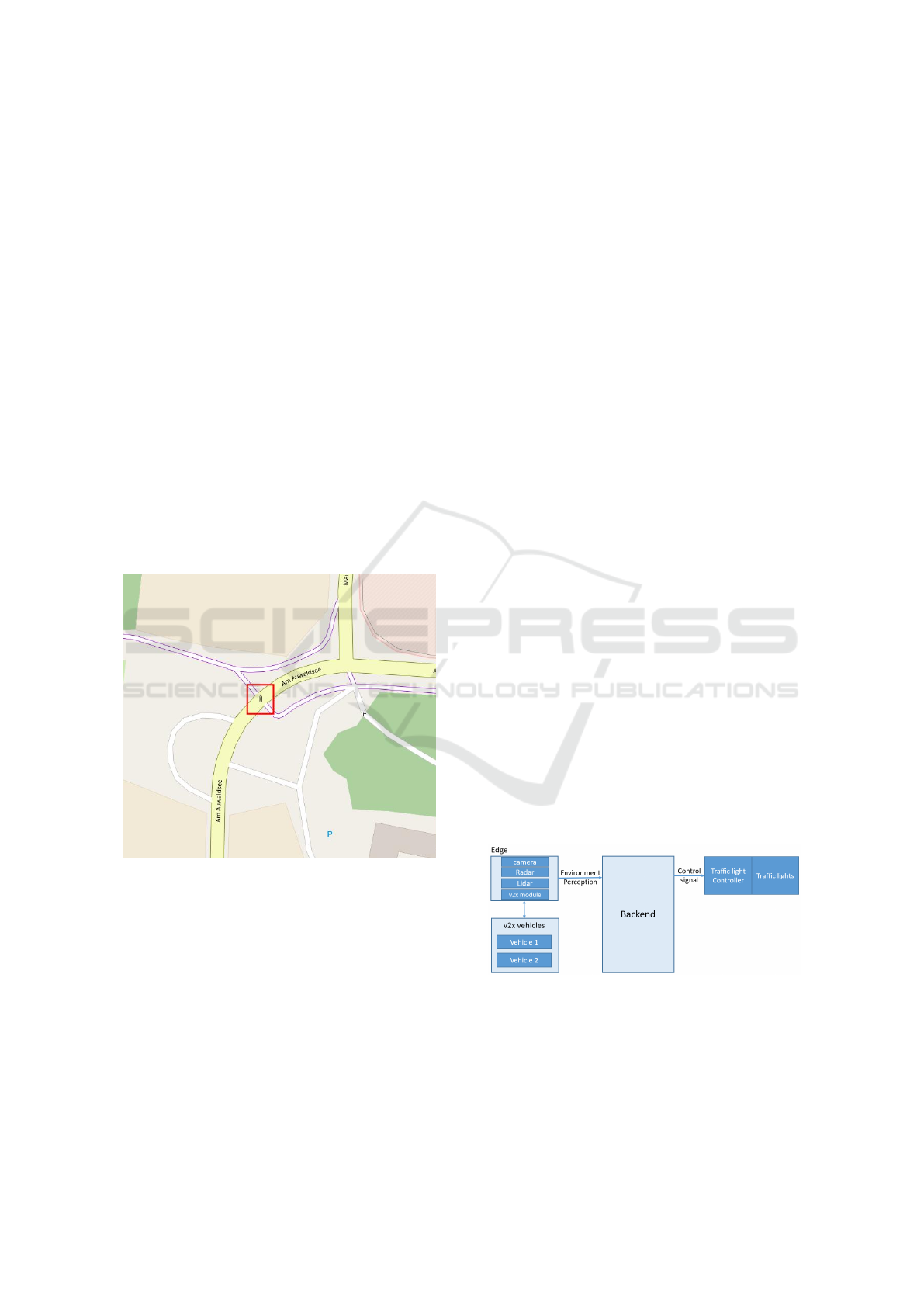
As shown in figure 1, the yellow lane is the vehicle
road (two lanes) and the narrow pink lane is the pedes-
trian and bicycle track. The traffic flow at the cross-
ing is managed by traffic lights as highlighted by the
red box. One smart infrastructure unit referred to as
an edge is developed to perceive the pedestrian cross-
ing junction and nearby lanes. This edge is equipped
with a high-resolution Radar, high-resolution LiDAR,
multiple RGB cameras, and one v2x communication
module. The edge is connected with a central back-
end system which acts as a final decision-maker. In-
formation about road users is sent by the edge to the
backend using a dedicated communication protocol
and then the backend controls the traffic lights ac-
cordingly. Further backend generates critical warn-
ings and other information signals which are com-
municated to vehicles through the v2x module of the
edge.
Figure 1: Smart infrastructure location.
This paper is structured as follows: Section II
highlights the main use-cases of the work, section
III introduces the architecture of the complete system
and further describes the details of each component
and then Section IV provides the conclusion and fu-
ture work.
2 USE CASES
The work focuses on two main use-cases
1. Traffic flow optimization – It means that depend-
ing on the real-time traffic on the vehicle lane
and on the pedestrian lane, the traffic lights are
switched on/off at the crossing junction by the
backend. The real-time traffic information is per-
ceived, processed, and send by the edge to the
backend to make decisions. This can further also
include prioritization of the emergency vehicles.
2. Assisting vehicles on the road – It means prov-
ing real time information and/or critical warn-
ings/alerts to the passing by vehicles via V2X
communication. This includes to
• Send timestamp information about the current
and next state of the traffic light to allow vehi-
cles to pass efficiently with less braking.
• Send warning to vehicles if some non-VRU like
an animal, football, or other object detected in
the vehicle lane around the crossing junction
• Send the maximum speed limit info of the area
to passing vehicles and also to send a warning
if the speed limit is violated.
• Send a signal to an emergency vehicle in case
of an accident in the monitoring area
• Send warning to other vehicles in case some
emergency vehicle is passing from the monitor-
ing area.
3 ARCHITECTURE AND THE
MAIN COMPONENTS
The Development of smart infrastructure involves the
active and flawless interaction of multiple compo-
nents. These components are both software as well as
hardware. To introduce all these major components,
the high-level architecture of the complete system is
shown in figure 2. These include
Figure 2: High-level architecture.
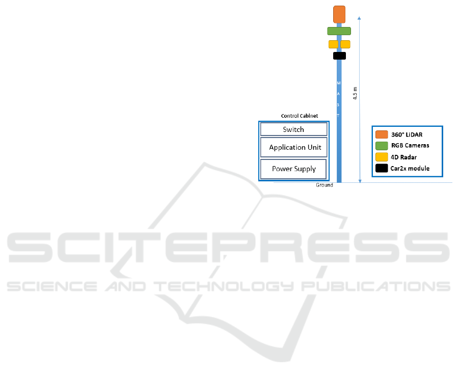
1. Edge – pole-like structure unit as shown in Fig-
ure 3, where multiple sensors and V2X module
are mounted and calibrated. This is used for envi-
ronment perception through sensor data fusion in
real-time at the crossing junction.
Concept of Smart Infrastructure for Connected Vehicle Assist and Traffic Flow Optimization
361
2. Backend – the central system which receives the
data from an edge (could also be multiple edges
in the future) and also from on-field vehicles via
edge. It decides when to change the states of traf-
fic lights and also when and which information or
warning to send to passing by vehicles.
3. Traffic light controller and traffic lights – this can
be considered as the final actuating component
which receives the control signal from the back-
end and changes the states of one or more traf-
fic lights accordingly, to optimize the traffic flow
at the crossing junction. In case, communication
with the backend fails, then the traffic controller
runs the traffic lights in default time-based mode.
4. Communication – even though this component
is not so effectively visible in figure 2, it is the
backbone of the complete system. This module
includes two types of communication - between
the edge and the backend via SENSORIS and
between vehicles and the edge through the V2X
module (CPM, CAM, and DENM protocols).
5. V2X enabled vehicles – test vehicles that are an
active part of the system to test all the use-cases
which include assisting through infrastructure.
Details of each component – the edge, the back-
end, traffic light controller, communication, safety,
and security are described further in this section. V2X
enabled vehicles are currently considered outside the
scope of this paper as they are third-party vehicles and
do not involve active development in the scope of the
work.
3.1 Edge
The smart infrastructure unit that comprises multiple
sensors and a v2x module is known as the edge. For
the current work, as stated before one edge is devel-
oped for research and testing purposes. As shown in
figure 3, the edge has three main components 1. Mast
– pole like mechanical structure 2. Multiple sensors
and v2x module mounted on top of the mast 3. Con-
trol cabinet – contains all the other required comput-
ing, control, and power supply components (located
on the ground).
Environment perception using edge means detec-
tion, classification, and tracking of the vehicles and
VRUs. There are three main broad categories of ob-
jects around crossing junction which has to be accu-
rately perceived. One is vehicles which include cars,
trucks, buses, vans, emergency vehicles, etc. which
travel through the vehicle lane across the junction.
The second category is VRUs which include walk-
ing person (adult or child), jogger, bicyclist, e-scooter
traveler, person walking with child carriage, group
of people (two or more), etc. which travels through
pedestrian lane across the junction. The third cate-
gory is non-VRUs – includes unknown large objects,
animals, etc. whose path is unknown and random.
Figure 3: Edge.
As per the geography of the selected pedestrian
crossing junction, it is required to detect and classify
VRUs up to 50 m from the junction on either side and
to detect and classify vehicles up to 100 m from the
junction on either side. Further detection and classifi-
cation of non-VRUs are required when they are very
close to the junction (around 20 m on either side) and
probably can obstruct the traffic flow.
As the task of infrastructure-based perception
shares the common goal with most of the autonomous
vehicle’s perception pipeline, it is wise to use the sen-
sors developed for the autonomous vehicles. Keeping
this in mind, the most widely used and matured tech-
nology of sensors - LiDAR, Radar, and RGB cameras
are selected.
The selection of a specific model and the man-
ufacturer for the individual sensor is carried out by
first doing an extensive search to select best-fit sen-
sors as per price and availability. Later, a decision
matrix based on all the requirements for each selected
model of sensor type is developed. As per the out-
come of the decision matrix, the best of two or three
sensors are selected. At last, selected sensors were
mounted on the mast of the lab setup and tested for
final analysis. With the comparative analysis for each
model, sensors of each type are finalized for the re-
search work.
The hardware architecture of the Edge is shown in
figure 4.
Each sensor perceives the environment within its
VEHITS 2022 - 8th International Conference on Vehicle Technology and Intelligent Transport Systems
362
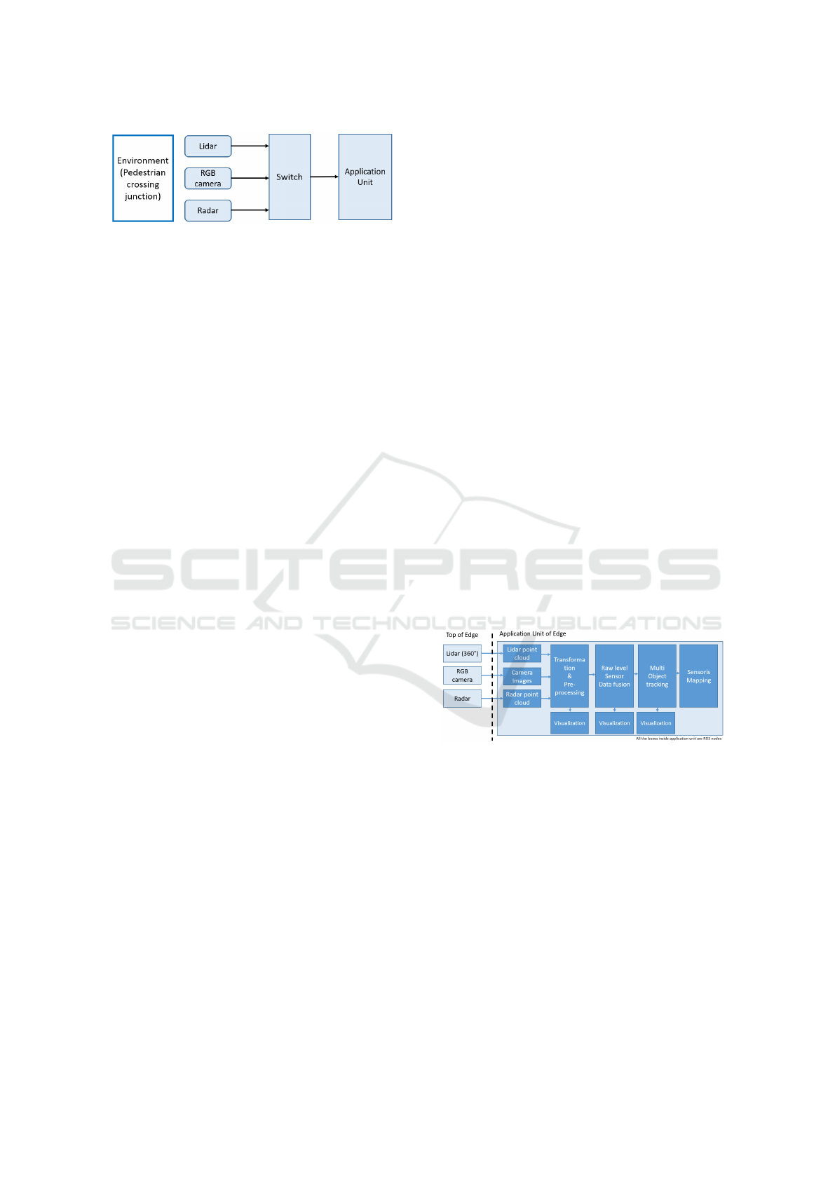
Figure 4: Edge hardware architecture.
Field of View (FoV). As shown in figure 4, LiDAR,
Radar, and camera units are connected to the switch
using Ethernet 1G connection. Further, the switch is
connected to the central application computer which
does all the software development of the edge. All
the sensors are powered using a 12 or 24 V DC power
supply. The switch is powered using a 48V DC power
supply. The application unit is a high computing
desktop computer that consists of multi-core CPUs
and dedicated GPU to develop and deploy AI algo-
rithms for sensor fusion.
The goal of this research in the direction of en-
vironment perception is to detect, classify and track
vehicles and VRUs in different weather and light con-
ditions. As each sensor has its pros and cons, to com-
plement them, sensor fusion is developed in the ap-
plication unit. Further, this work specifically aims to
develop and implement AI-based raw level sensor fu-
sion algorithms to fuse the raw data from two or more
sensors for finding optimum solutions and parame-
ters for different light and weather situations across
the junction. The raw level sensor fusion is selected
over object-level fusion to explore the benefits of us-
ing complete data available from sensors.
As described in figure 5, raw data of LiDAR, i.e.
point cloud, raw data from cameras, i.e., RGB images,
and raw data from Radar, i.e., radar detection points
are acquired from sensors and sent to the application
unit at a pre-defined data rate. At present, this data
rate is defined as 10 Hz for each sensor. For the de-
velopment of a software framework, Robot Operating
System (ROS) is used.
To apply AI-based algorithms, labeled data is re-
quired. For this purpose, the sensors are mounted
on the lab mast using customized 3D mountings, and
then they are calibrated with each other and also with
edge to get the data in edge coordinate frame. Further,
all the sensors are synchronized together using com-
mon time reference before collecting the data in the
application unit. To label the sensor data, methods
involving both manual labeling and semi-automatic
labeling are used. Further specific scenarios with
pedestrians and vehicles equipped with GPS and IMU
systems are also designed to collect ground truth data.
In order to use the raw data directly as fusion, two
approaches are finalized after doing a literature survey
(Chadwick et al., 2019) (Chang et al., 2020). In the
first approach, the radar point cloud is transformed
into an RGB plane, and values of radar, i.e. spatial
information (X, Y, Z) and measurement information,
i.e. range, doppler velocity, and RCS are encoded to
RGB values. Similarly, the lidar dense point cloud is
transformed and encoded into a separate RGB plane.
These results in 3 independent RGB planes, each from
radar, lidar, and camera for the same instance. These
are then at first fed into a few separate CNN layers
to extract high-level features, then added together and
further passed through more CNN layers to finally get
the object position and class information.
In the second approach of the raw sensor fusion,
the radar and Lidar 3d point cloud data is encoded
into a separate 3D voxel grid. Then the 3d voxel grid
input is fed to 3D CNN layers to extract upper layer
features separately for radar and Lidar. Camera RGB
images are fed into 2D CNN layers. After extrac-
tion of high-level features, an intermediate later is de-
signed to transform the features in a common plane,
then added together and further trained using more
layers to finally extract object position and class.
The sensor fusion algorithm provides position,
speed, and class of objects which are further tracked
using filters. The final track objects’ information is
sent to the backend. As per the perception informa-
tion processed and sent by edge, the backend takes
appropriate decisions to optimize the traffic flow and
also to assist passing vehicles by providing informa-
tion and/or warnings in real-time.
Figure 5: Edge software architecture.
3.2 Communication
An appropriate communication design enables the
promising information exchange among all intelligent
components in the entire system, which guarantees
the performance of the intelligent infrastructure-based
traffic services and applications. In this paper, the
challenges of efficient data sharing in communication
networks is specifically tackled, i.e., 1) highly hetero-
geneous networks for dissemination of various mes-
sages using V2V, V2C, V2I, etc. 2) variety of QoS
requirements in miscellaneous traffic services.
Concept of Smart Infrastructure for Connected Vehicle Assist and Traffic Flow Optimization
363
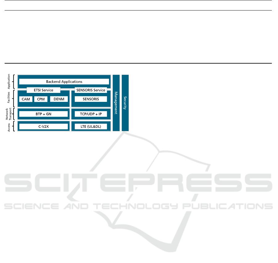
Table 1: Summary of QoS requirement for our use cases (UC) with respect to the specifications in 3GPP and 5GCAR.
Criteria UC 1: Connected Vehicle Assist UC 2: Traffic Flow Optimization
Latency 3–100 ms second level
Reliability 99.999% 90%
Throughput 1 Gbps 25 Mbps
Message type CPM & CAM & SENSORIS DENM & SENSORIS
Communication range 40-70 m few kms
V2X communication type C2V & I2V & I2C V2C & I2C
Speed of UEs 0-70 km/h (urban) 0-70 km/h (urban)
Figure 6: Proposed protocol stack in communication solu-
tion.
3.2.1 Interoperable Communication Framework
ERTICO SENSORIS (SENSORIS Innovation Plat-
form, ) und ETSI C-ITS V2X messages (ETSI TS
103 301 V1.3.1, 2020) are two main communication
frameworks in Cooperative Intelligent Transport Sys-
tem (C-ITS), which are open, standardized, and com-
monly accepted (Song and Festag, 2021). Specifi-
cally, ERTICO SENSORIS provides a sensor interface
between vehicles and the cloud via cellular communi-
cation. The detected objects in each vehicle equipped
with SENSORIS software can be uploaded in form of
the messages encoded using Google Protobuf. ETSI
C-ITS V2X messages is composed of a set of protocols
in the facilities layer of V2X protocol stack (Festag,
2015). By broadcasting various messages, e.g. Col-
lective Awareness Message (CAM), Cooperative Per-
ception Message (CPM), Decentralized Environmen-
tal Notification Message (DENM), the C-ITSs can
share the sensor information in an ad-hoc network
over ITS-G5 or C-V2X in 5.9 GHz frequency band.
To exploit the information in the road traffic and
interoperate the systems in hybrid networks together
with infrastructure and vehicle, we propose the pro-
tocol stack with both communication frameworks for
deployment, which is shown in Fig. 6. The main aim
to include both types of communication is to consider
possible interface compatibility for future expansion
of the project. Further, this will also help to gain suf-
ficient experience and development of required soft-
ware stack.
In addition as shown in Fig. 6 on the left side, the
system is designed for the V2X protocol stacks. C-
V2X with PC5 interface resides on the access layer.
GeoNetworking (GN) distributes the packets in the
geographical field and the basic transport protocol
(BTP) enables the multiplexing and demultiplexing of
messages on site of C-ITS. In the facilities layer, the
CAM, CPM, and DENM with corresponding ETSI
Service are employed for sensor data sharing. On
the right-hand side, LTE with uplink and downlink
(UL&DL) is set as the physical interface for commu-
nication to the backend. As the first cloud deploy-
ment, the TCP/IP-based Google SubPub is integrated
for SENSORIS message dissemination. Both ETSI
and SENSORIS services are defined as interfaces be-
tween application and facilities layers. Consequently,
the backend applications can take the actions depend-
ing on the information from the hybrid networks.
3.2.2 Individual QoS Design
The intelligent infrastructure system is aimed at pro-
viding vehicles with miscellaneous traffic services
and applications to accomplish a safer and more ef-
ficient road environment. Each traffic service or
application addressing associated use cases requires
individual communication quality (Kanavos et al.,
2021)(Abdel Hakeem et al., 2020). Tab. 1 shows
the summary of Quality of Service (QoS) requirement
for our use cases (UC 1: Connected Vehicle Assist
and UC 2: Traffic Flow Optimization) with respect
to the specifications in key international organizations
3GPP and 5GCAR (Condoluci et al., 2019).
Specifically in UC 1, the infrastructure can warn
the traffic participants, if potential risks on the road
are detected by the edge system. According to the
specific warning functions, the service will require
a corresponding latency range from 3 to 100 ms
in communications. Very high reliability and large
throughput can ensure the warning signals are gener-
ated correctly and received by other C-ITS in time.
CPM, CAM, and SENSORIS messages are employed
to carry the sensor information in the heterogeneous
networks. While the efficiency of traffic is opti-
VEHITS 2022 - 8th International Conference on Vehicle Technology and Intelligent Transport Systems
364
mized by controlling the traffic signals at the pedes-
trian crossing in UC 2, where the latency should be
on the second level and high reliability, as well as
25 Mbps throughput are sufficient for the related ser-
vices. DENM and SENSORIS carry the sensor infor-
mation and traffic events, such as traffic jams, and is
used by traffic signal controller to take the appropriate
actions, and hence improve the traffic efficiency.
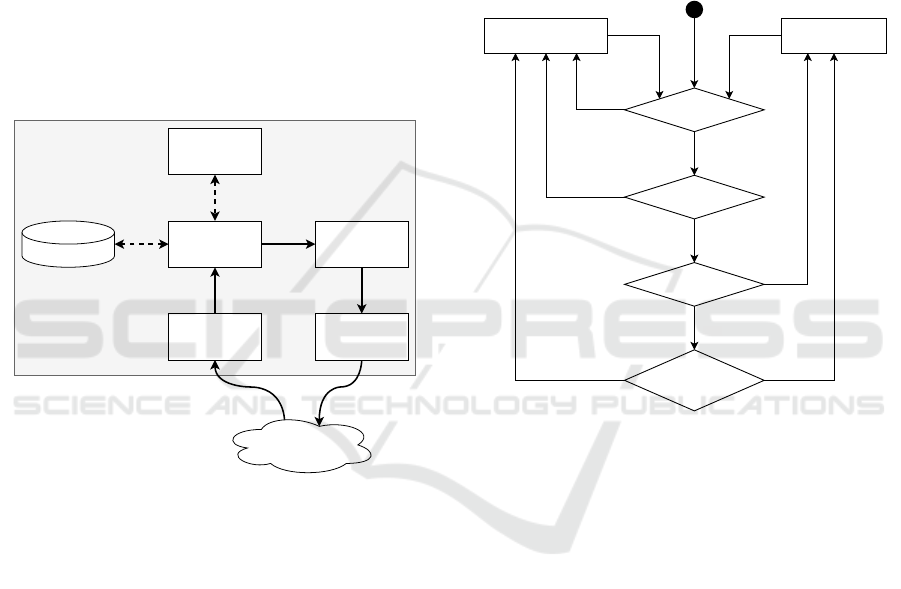
3.3 Backend
The backend module of the architecture is the part
where the intelligent decisions for the traffic lights are
made. It receives all road users detected by the Edge
and sends the recommended state of the traffic lights
based on them. Figure 7 depicts the inner architecture
of the Backend.
Google Cloud Platform (Pub/Sub)
Inbound
Adapter
State Machine
World
State
Service
Outbound
Adapter
Road User Cache
Decision Algorithm
Figure 7: Simplified inner architecture of the backend.
The message with the information about the cur-
rent road users is received by the inbound adapter. Af-
ter it is deserialized and validated, it is forwarded to
the World State Service. In this service, the road user
state will be stored in the Road User Cache. The cur-
rent traffic situation is derived from the Road User
Cache and subsequently, send to the Decision Algo-
rithm, which returns the recommended traffic light
event. This event is transferred to the State Machine.
When the state has changed, the State Machine passes
the new state to the Outbound Adapter. Here the
new state is processed and published to the Google
Pub/Sub system.
The Road User Cache represents the overall sit-
uation at the junction. Each contained road user is
identified by a specific ID. Additionally, it specifies
the following data - position, speed, confidence of ex-
istence, type, and confidence of type.
The Decision Algorithm takes the current junction
state and these road users as input and generates a
junction event as output. Currently, two different ap-
proaches for the calculation are being evaluated.
Algorithm I: Self-developed Algorithm. It consid-
ers many situations and creates the result determin-
istically. This includes situations where pedestrians
only, cars only, or both are waiting or emergency traf-
fic such as ambulances are present.
Pedestrians
can cross
Vehicles can cross
No
Yes
SRU present?
Yes
No
VRU present?
Yes
No
NVRU present?
Yes
No
VRU waited
enough?
SRU := Special Road User (Emergency vehicle)
VRU := Vulnerable Road User (Pedestrian, Cyclist)
NVRU := Non Vulnerable Road User (Car)
Figure 8: Simplified static algorithm with some details
omitted for brevity.
Algorithm II: Deep Learning. Furthermore, the sec-
ond algorithm is a deep neural network. Its training
happens through reinforcement learning, i.e. no train-
ing data is required. The network can be trained to
lower the waiting time or – for a more environmen-
tally friendly approach – the CO
2
emission of a road
user at the junction. The benefits of such a Deep Re-
inforcement Learning approach could be:
• The neural network learns over time and can make
decisions based on historic data.
• It can also adapt to new circumstances without the
need to rewrite the algorithm.
• This autonomous dynamic learning process can
optimize the algorithm even more than a static
hard-coded decision procedure.
This approach bears some challenges mainly concern-
ing the validation of the different results of the net-
work. There must be mechanisms to outvote the neu-
ral network, e.g., to ensure that there is not a starva-
tion problem for one of the sides.
Concept of Smart Infrastructure for Connected Vehicle Assist and Traffic Flow Optimization
365

Both strategies (Algorithm I & II) have to be
tested extensively.
3.4 Traffic Light Control
The traffic light controller module is the final compo-
nent to optimize the traffic flow at the crossing junc-
tion. For the two main lanes - the vehicle lane and
the pedestrian lane, two different traffic lights are se-
lected. These are used for the final demonstration of
the complete system. The traffic light module with
two lights – green and red is used for the pedestrian
lane and the traffic light module with three lights –
green, amber, and red is used for the vehicle lane.
The main components of the traffic light controller
module are DC power supply unit, DC Splitter, 8 in-
put DC relay board, raspberry pi as the control unit,
and two traffic lights modules.
Figure 9: Traffic light controller block diagram.
The block diagram shown in figure 9 highlights
the flow of signals for traffic light control. The back-
end which resides in the cloud connects itself via the
internet to the controller. The python API running in
the controller reads the decision from the backend and
accordingly sends the signal to switch ON or OFF one
or more traffic lights via serial communication to the
relay circuit. At last relay circuit activates or deacti-
vates the respective traffic light.
3.5 Safety and Security
Networking and digitization are unthinkable with-
out information security. V2X communication, au-
tonomous driving, and digitization are just a few ex-
amples of future topics that are being incorporated
into the development of a new generation of vehicles
and infrastructure. The increasing networking of ve-
hicles and intelligent infrastructure not only increases
the complexity, but also the vulnerability of such sys-
tems to cyber-attacks.
The major subsystems of this project, i.e., the edge
and the backend, and the communication interfaces
between them are at a risk from a safety and security
perspective.
A system is at risk with one of the impact cate-
gories - operational readiness/capability, safety, pri-
vacy, and financial impact.
In addition to safety, data from the sensors, such as
cameras at the traffic lights, which are pre-processed
in the edge or during further processing in the back-
end, must be protected from unauthorized access.
To comply with safety and security requirements,
primarily the international standards, ISO/SAE 21434
(road vehicles cyber-security engineering) (ISO/SAE
21434:2021, ), ISO 26262 (road vehicles func-
tional safety (ISO 26262-1:2011, ) and ISO 27000
series (information technology security techniques)
(ISO/IEC 27000:2018, ) are considered. Using these
standards, the two major safety goals for this work
are derived. These safety goals states that smart in-
frastructure system should not send a false warning to
the vehicles and the traffic lights at junctions should
be green in conflicting directions at the same time.
4 CONCLUSIONS
This paper addresses the challenges in the intelligent
transport system and focuses on infrastructural so-
lutions. Based on a thorough analysis of two use
cases - Connected Vehicle Assist and Traffic Flow Op-
timization, the concept of an intelligent infrastruc-
ture system is proposed, which enables traffic data
collection through perception and V2X communica-
tion. Through data fusion at the roadside edge com-
puters, traffic safety and efficiency can be improved
by cloud-based backend via traffic light control and
sending V2X messages to connected vehicles. The
safety and security of the entire system have been an-
alyzed, which ensures the success of future deploy-
ment and testing on public roads.
ACKNOWLEDGEMENTS
This work is supported by the Bavarian Ministry of
Economic Affairs, Regional Development and Energy
(StMWi) in the project “INFRA – Intelligent Infras-
tructure”. We would like to thank Mr. Sebastian
Mauthofer for feedback on safety and security regard-
ing the design of infrastructure systems.
REFERENCES
Abdel Hakeem, S. A., Hady, A. A., and Kim, H. (2020). 5g-
v2x: standardization, architecture, use cases, network-
slicing, and edge-computing. Wireless Networks.
Agrawal, S. and Elger, G. (2021). Concept of infrastructure
based environment perception for in2lab test field for
automated driving. In 2021 IEEE International Smart
Cities Conference (ISC2), pages 1–4.
VEHITS 2022 - 8th International Conference on Vehicle Technology and Intelligent Transport Systems
366

BW-test field. Test Area Autonomous Driving Baden-
W
¨
urttemberg. https://taf-bw.de/en/the-test-field. Ac-
cessed 06.03.2021.
Chadwick, S., Maddern, W., and Newman, P. (2019). Dis-
tant vehicle detection using radar and vision. In 2019
International Conference on Robotics and Automation
(ICRA), pages 8311–8317.
Chang, S., Zhang, Y., Zhang, F., Zhao, X., Huang, S., Feng,
Z., and Wei, Z. (2020). Spatial attention fusion for ob-
stacle detection using mmwave radar and vision sen-
sor. Sensors, 20(4).
Condoluci, M., Gallo, L., Mussot, L., Kousaridas, A., Spa-
pis, P., Mahlouji, M., and Mahmoodi, T. (2019). 5g
v2x system-level architecture of 5gcar project. Future
Internet, 11(10).
dai-labor TU Berlin. Autonomous Mobility Test bed. https:
//dai-labor.de/en/testbeds/autonomous-mobility/. Ac-
cessed 07.03.2021.
ETSI TS 103 301 V1.3.1 (ETSI Std., 2020). Intelligent
transport systems (its); vehicular communications; ba-
sic set of applications; facilities layer protocols and
communication requirements for infrastructure ser-
vices.
Festag, A. (2015). Standards for vehicular communication –
From IEEE 802.11p to 5G. Elektrotech. Inftech. 132,
page 409–416.
ISO 26262-1:2011. ISO 26262-1:2011 Road vehicles
— Functional safety. https://www.iso.org/standard/
43464.html. Accessed 08.03.2021.
ISO/IEC 27000:2018. ISO/IEC 27000:2018 Information
technology — Security techniques — Information se-
curity management systems . https://www.iso.org/
standard/73906.html. Accessed 08.03.2021.
ISO/SAE 21434:2021. ISO/SAE 21434:2021 Road vehi-
cles — Cybersecurity engineering. https://www.iso.
org/standard/70918.html. Accessed 08.03.2021.
Kanavos, A., Fragkos, D., and Kaloxylos, A. (2021). V2x
communication over cellular networks: Capabilities
and challenges. Telecom, 2(1):1–26.
providentia++. Providentia++: Research for auto-
mated driving with external infrastructure. https://
innovation-mobility.com/en/. Accessed 06.03.2021.
RWTH Aachen University - ika. ACCorD - Research
Project. https://www.ika.rwth-aachen.de/en/research/
projects/automated-driving/3255-accord.html. Ac-
cessed 06.03.2021.
SENSORIS Innovation Platform. Sensor Interface Speci-
fication, Version 1.1.1. https://bit.ly/2Qf49nZ. Ac-
cessed 17.11.2021.
Song, R. and Festag, A. (2021). Analysis of existing ap-
proaches for information sharing in cooperative intel-
ligent transport systems – V2X messaging and SEN-
SORIS. In 2021 FISITA World Congress.
Concept of Smart Infrastructure for Connected Vehicle Assist and Traffic Flow Optimization
367
