
Enterprise Maps: Zooming in and out of Enterprise Models
Maja Spahic-Bogdanovic
a
and Knut Hinkelmann
b
School of Business, FHNW University of Applied Sciences and Arts Northwestern Switzerland, 4600 Olten, Switzerland
Keywords:
Enterprise Architecture, Enterprise Modeling, ArchiMate, Zoomability, Zoomability Principle, Enterprise
Architecture Navigation.
Abstract:
A company’s architecture can be represented by domain-specific models, which are defined by domain-specific
modeling language. Since not all stakeholders are interested in the same models, dedicated views can be
created to support navigation through the enterprise models. These views offer a snippet of the entire company
and cover stakeholder-specific concerns. The relationships between the different views and models remain
hidden and can be unveiled with much effort. The developed concept of the zoomability principle offers the
ability to change the degree of detail using zoom in and out of the enterprise model. The different models
and modeling languages used to express an enterprise are considered, and a form of navigation is established
similar to an online map. The concept is based on two pillars, ”Zoom Within” and ”Zoom into Complements”.
For this purpose, a metamodel was developed, which formalizes the elements used in the concept and their
relationships. Developing the artifact, rules were defined that contribute to a generic approach allowing an
application to another case. Furthermore, a prototype was developed, representing the zoomability principle
and offering the possibility to perform zooming behavior. The artifact was evaluated through a demonstration.
An additional prototype was created to demonstrate that the developed concept can be applied to a predefined
set of situations.
1 INTRODUCTION
The goal of enterprise modeling (EM) is to sup-
port enterprise analysis, communication, collabora-
tion, and decision making by representing the en-
terprise from multiple perspectives (Vernadat, 1996).
The different graphical models support communica-
tion between the stakeholders involved in the design
of the enterprise (Hinkelmann et al., 2016). Models
are the result of a construction process in which the
perception of reality or what has to be redesigned is
described using a modeling language (Sandkuhl et al.,
2014). The individual models consist of graphical el-
ements and relations, which are defined in the meta-
model. Since not all stakeholders are interested in the
same information, dedicated views can be created to
address specific concerns (ISO 42010, 2011). These
views offer a snippet of the entire company. The re-
lationships between the individual views and models
are not visible or can be unveiled with a lot of effort.
Taking a map as a metaphor, the views remind us
of the time before online maps existed. Paper maps
a
https://orcid.org/0000-0003-1625-0162
b
https://orcid.org/0000-0002-1746-6945
were used in the decency of a digital map, which
showed a specific area to a certain degree of detail,
like an overview or detailed maps of particular ar-
eas. Another map was needed if the desired location
was outside the map or to get a more detailed view.
Furthermore, there are maps with different scales for
overview maps on country levels and detailed city
maps. The current situation in using enterprise mod-
els evokes this time.
Digital maps, however, do not need separate maps.
It is possible to navigate in a single environment.
When zooming into a map, more details become vis-
ible. Figure 1 shows an example from Google maps
with an overview map of Europe. When zooming in,
more and more details become visible. On a city level,
details like streets and additional information like ho-
tels and restaurants become visible - depending on the
user’s concerns.
Lankhorst et al. (2017) mentioned the poor defi-
nition of the relations between the different views for
enterprise models and pointed out that created mod-
els are not further integrated. The entire overview
of the links between the individual models and the
possibility of zooming in and out the enterprise mod-
els and thus changing the degree of detail is a de-
Spahic-Bogdanovic, M. and Hinkelmann, K.
Enterprise Maps: Zooming in and out of Enterprise Models.
DOI: 10.5220/0011063700003179
In Proceedings of the 24th International Conference on Enterprise Information Systems (ICEIS 2022) - Volume 2, pages 515-526
ISBN: 978-989-758-569-2; ISSN: 2184-4992
Copyright
c
2022 by SCITEPRESS – Science and Technology Publications, Lda. All rights reserved
515
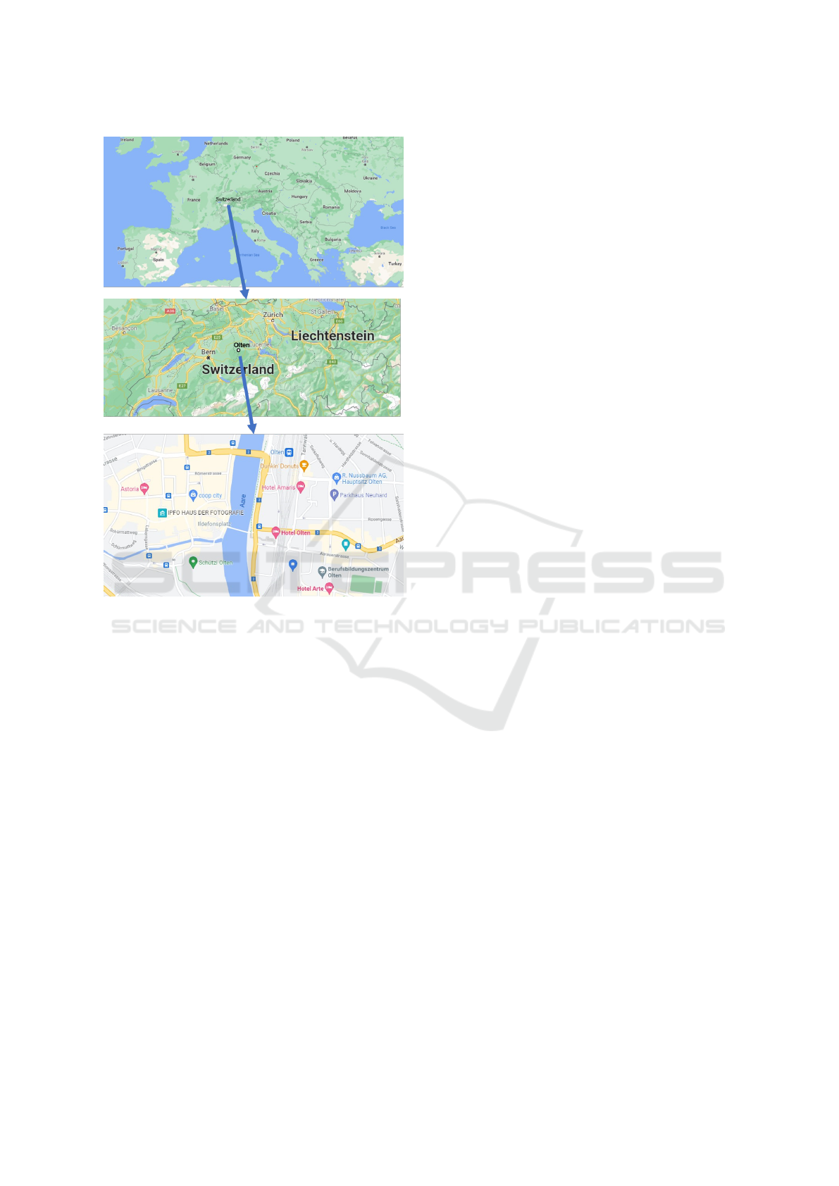
Figure 1: Zooming into an online map.
sire that has not yet been satisfied (Bork and Al-
ter, 2018). This concept of ”zoomability” (Bork and
Alter, 2018) would bring significant benefits to the
decision-makers to see the relationships and depen-
dencies between the models visualized and be able to
identify the potential impact of a change to the com-
pany. The principle of zoomability is adopted from
online maps and applied to enterprise models.
This paper introduces a concept that establishes
zooming in and out and navigation in enterprise mod-
els like an online map. The Design Science Research
(DSR) paradigm was followed to identify practice
problems and develop and evaluate a prototype. The
main contribution is a zoomability concept that allows
stakeholders to see relationships across views and en-
rich the view with more detailed models.
This article is structured as follows: In Section 2
the relevant information about Enterprise Modeling
and Enterprise Architecture as well as techniques for
navigation through enterprise models are introduced.
Section 3 focus on the methodology, Section 4 fo-
cuses on input from the practice and Section 5 intro-
duces the concept of ”zoomability”. In Section 5.4 the
meta model of the concept and a formalization of the
rules are presented. Section 6 explains the evaluation
and in Section 7 the conclusion is presented.
2 STATE OF THE ART
This section creates an awareness of the area of inter-
est. It provides the fundamentals as the current state
of research in the area of Enterprise Modeling (EM),
Enterprise Architecture (EA), and navigation and vi-
sualization approaches.
2.1 Enterprise Modeling and Enterprise
Architecture
Enterprise modeling refers to the abstract representa-
tion of different perspectives using enterprise model-
ing methods and languages (Vernadat, 1996). Repre-
senting a holistic view of an enterprise in one model is
unrealistic (Vernadat, 2014). Therefore, a large num-
ber of different models represent the company from
different viewpoints. A widely used approach is to
partition the enterprise models into separate views
covering a specific aspect of the architecture. The fo-
cus is set on stakeholder and their concerns while ex-
cluding others. Tailored views with relevant models
are created. The concept of modeling views and view-
points has been standardized in (ISO 42010, 2011).
Different methods, tools, and best practices are
offered to cover the various perspectives of an en-
terprise. These perspectives are expressed as a set
of different models. For various stakeholders and
concerns, there can be different modeling languages.
The advantage of different modeling languages is that
they are adequate for certain kinds of information
(Bjekovic et al., 2012). While a process map pro-
vides an overview, a process model represents a flow
of work in a single process. If a process flow is mod-
eled, the focus is on different information than if the
architecture is represented.
Enterprise Architecture (EA) has become increas-
ingly important to enable a holistic view of the enter-
prise. An EA model describes the overall design of
the enterprise, including its components and the con-
nections between them on different layers (Ahlemann
et al., 2012; Lankhorst et al., 2017). These layers
cover information starting at the enterprise strategy
to the infrastructure layer. The different layers are re-
flected in Enterprise Architecture Frameworks (EAF)
like the Zachman Framework (Zachman, 2016), TO-
GAF (The Open Group, 2018) or ArchiMate (The
Open Group, 2019a).
ArchiMate is a prominent domain modeling lan-
guage for describing EA (The Open Group, 2019a).
ICEIS 2022 - 24th International Conference on Enterprise Information Systems
516
An advantage of ArchiMate is that it can be mapped to
TOGAF (Desfray and Raymond, 2018) and Zachman
Framework (Zachman, 2016). ArchiMate is an at-
tempt to develop a unified modeling language that can
integrate relevant aspects of a company (Lankhorst
et al., 2010). It is a common, standardized modeling
language for enterprise architecture. It is not intended
to displace other modeling languages like BPMN,
UML, or ERM, which cover different concerns on de-
sign level (Ahlemann et al., 2012). ArchiMate should
be seen as an umbrella and various Domain-Specific
Modeling Language (DSML) as an enhancement of
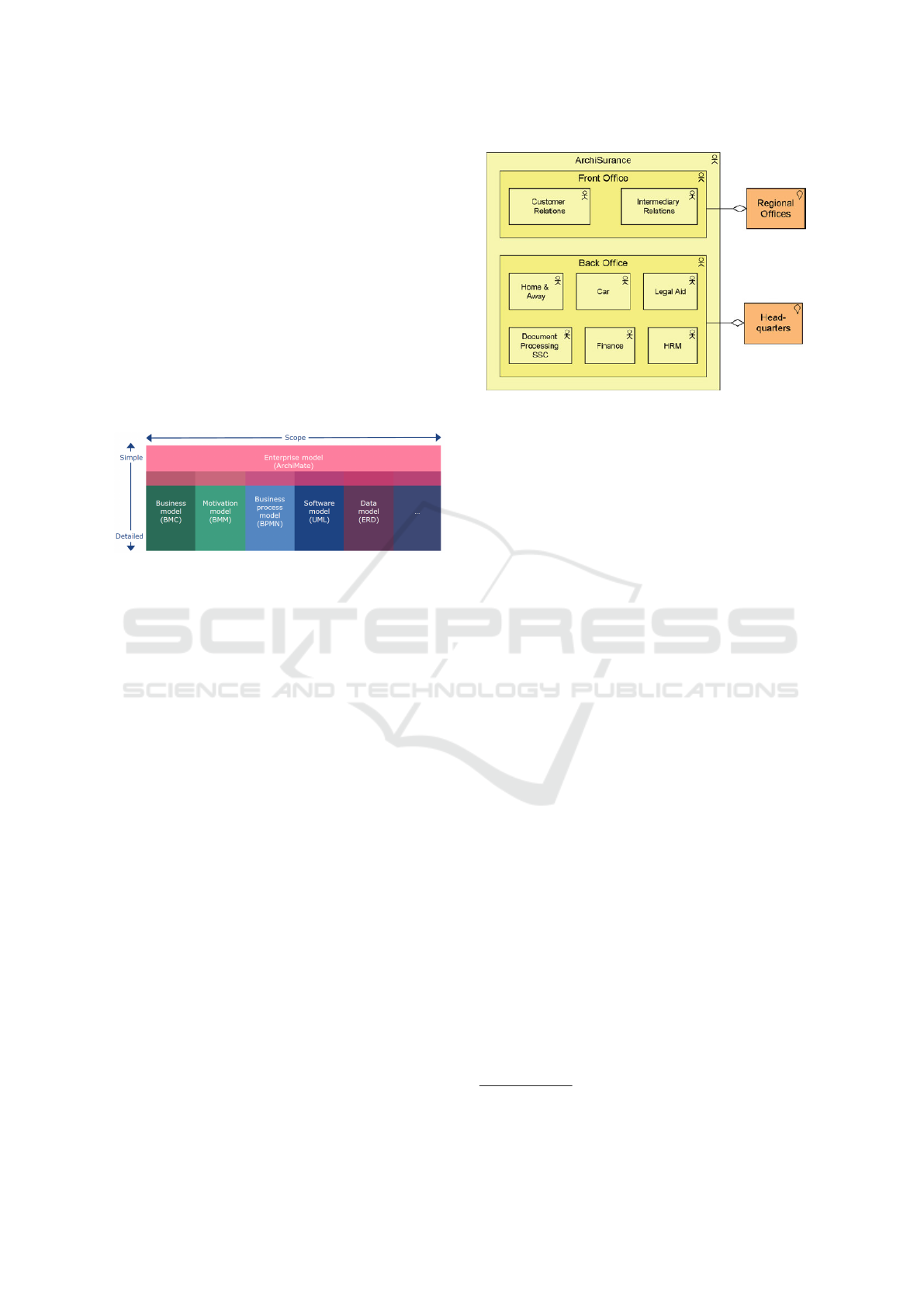
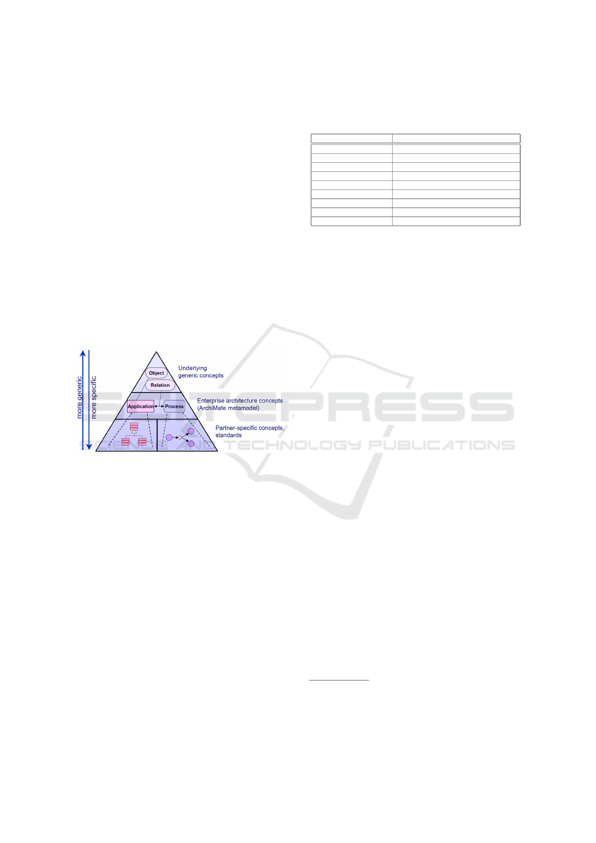
the level of detail (Lankhorst et al., 2017). Figure 2
visualizes the level of details and the scope of various
modeling languages.
Figure 2: ArchiMade as umbrella (Lankhorst et al., 2017).
2.2 Techniques for Visualizing
Enterprise Architectures
In ArchiMate, viewpoints are an essential concept
that enables the modeling of specific aspects of the
enterprise architecture (Lankhorst et al., 2017). A
viewpoint contains a subset of ArchiMate elements
and their relationship, covers one or more stakeholder
concerns, serves a specific purpose, and covers a spe-
cific scope (The Open Group, 2019b). A view repre-
sents a subset of the Enterprise Models using only the
concepts and relationships of the viewpoint. Figure 3
shows an example of an ArchiMate view representing
the high-level organization model of an enterprise.
Javed et al. (2015) emphasize in their paper how
important it is for a system architect to be able to
”zoom in” and ”zoom out”, for example, ”zoom in”
from an overview model into details of the system.
Javed et al. (2015) makes extensive use of business
and technology patterns, and based on user input as
well information from the existing views, multi-views
are created. This approach combines two concerns,
those of enterprise architecture and information sys-
tems development. It also promotes the development
of downstream artifacts by using the upstream archi-
tecture description as a reference (Javed et al., 2015).
This approach requires that the enterprise models are
semantically enriched, and a repository is in use.
Figure 3: Organisation View (Lankhorst et al., 2017).
Van der Torre et al. (2006) have introduced a for-
mal model for landscape maps. A matrix is the ba-
sis of a landscape map, whereby the dimensions are
freely selectable. Van der Torre et al. (2006) argues
that the 2D landscape maps are simple to read and
provide an overview of architecture relations across
layers. Using a 2D landscape map offers a good
overview of the EA, but with increasing complexity
and dimensions, it becomes difficult to navigate be-
tween the maps.
In certain domains, the zoom in and out function is
already common. In the process architecture, the de-
composition relationship is already established. Ac-
cording to Dumas et al. (2013) decomposition reveals
a hierarchical relationship. The different levels are vi-
sualized in the form of a pyramid, which specifies the
level of detail. The first level corresponds to the pro-
cess map, the second level shows the business process
model, and the third level shows the business process,
including exposed sub-processes.
Osterwalder et al. (2014) have developed the
Value Proposition Canvas as a detailed view of two
blocks of Business Model Canvas, the value proposi-
tion and customer segments. The Value Proposition
Canvas is used to develop ideas, concepts, and busi-
ness plans for new products and services.
2.3 Zoomability in EA Tools
The zoom in and out of an enterprise model refers
to the enlargement or reduction of a specific model.
Thereby, no additional details are added to or re-
moved from the enterprise model.
Modeling tools like Visual Paradigm
1
or Enter-
prise Architect
2
offer a zoom in functionality that
changes the section but not the level of detail. Both
1
See https://www.visual-paradigm.com/
2
See https://sparxsystems.com/
Enterprise Maps: Zooming in and out of Enterprise Models
517

tools also offer the possibility to create hyperlinks
as 1:n relationships from elements of one enterprise
model to a more detailed model. For example, a hy-
perlink can connect a process element in an architec-
ture model to a more detailed architecture model rep-
resenting its subprocesses or a BPMN model repre-
senting the process flow. The modeler explicitly adds
the links and can be used for zoomability. Mapping
on the meta-level is not supported.
2.4 Approaches for Navigation and
Zooming
Rehring et al. (2019) developed an approach inspired
by a city metaphor. The EA objects are replaced by
the objects of a city map and thus defined as a new
formal language. For example, the streets represent
the business process, and the car represents the data
transport.
To promote navigation, other approaches have
been pursued. Rehring and Ahlemann (2020) have
developed a new approach that visualizes EA through
Augmented Reality (AR). The approach consists of a
three-layer model, each containing relevant EA ele-
ments. As soon as an EA object in the model is se-
lected, relationships to the object in the underlying
layer are displayed.
3 METHODOLOGY
The Design Science Research (DSR) paradigm was
followed to develop the artifact. The core of DSR
is the development of an artifact following a five-
step iterative problem-solving process (Vaishnavi and
Kuechler, 2015).
The first phase of the research focused on un-
derstanding the problems with the current visualiza-
tion and navigation approaches through literature re-
view, unstructured interviews with practitioners, and
a case study. For the interviews, senior consultants
of two consulting companies were approached, each
having years of practical experience in implementing
EA projects. The interview’s main focus was to get
insight into already implemented projects and how the
consultants designed the navigation between the dif-
ferent enterprise models.
The case study refers to the fictitious
ArchiSurance case provided by The Open Group,
which shows a practical application of ArchiMate
(Jonkers et al., 2019). Analyzing the implementation
of ArchiMate on a case offers the possibility to iden-
tify potential improvements in terms of navigation
with and between the individual models and layers.
The analysis of the existing navigation approaches
formed the basis for the research.
In the suggestion phase, the preliminary idea for
the problem-solution was specified. Subsequently, the
concept was further refined and implemented as a pro-
totype. The result of the development phase was an
artifact that implements the concept of navigation en-
abling zoomability. The developed artifact improves
the usefulness of enterprise models in terms of navi-
gation.
For evaluation, the concept was applied to another
case. A new prototype was built by means of scenar-
ios, which demonstrates that the artifact is a generic
solution.
4 UNDERSTANDING THE
NAVIGATION PROBLEM IN
THE PRACTICE
To understand the navigation problem from a prac-
tical point of view, the various models of the ficti-
tious ArchiSurance case were analyzed (Jonkers et al.,
2019), and interviews with senior consultants were
conducted. The implementation of the case follows
the Architecture Development Method of TOGAF
(Desfray and Raymond, 2018). Each phase addresses
an architecture layer. Defining views offers the possi-
bility of focusing on the essential aspects relevant to
certain stakeholders and their concerns. The views act
as dedicated entry points into the enterprise models.
The interviews with the practitioners were struc-
tured as an open discussion. The aim of the interviews
was to learn more about how people in a company
navigate in a large set of models. For this purpose,
the interview partners showed various practical exam-
ples which were realized in different companies. Typ-
ically, companies have a model of the EA landscape,
which provides an overview of the company’s enter-
prises architecture. The landscape is usually inspired
by ArchiMate layers, offering the individual adjust-
ment according to the stakeholder requirements. The
stakeholder concerns are covered by different views
placed on the different layers. Each view unveils a
dedicated model.
The advantage of this solution is the reduction of
complexity. The disadvantage, however, is that the
relationship between the individual views is not ap-
parent. The relationships between the individual ele-
ments of the views are difficult to identify, in particu-
lar, because the same elements can appear in several
views. Furthermore, ArchiMate is not appropriate to
model details of business processes or data, such that
ICEIS 2022 - 24th International Conference on Enterprise Information Systems
518
references to other modeling languages like BPMN or
ER diagrams need to be made.
5 NAVIGATION CONCEPTS FOR
ENTERPRISE MODELS
This chapter provides information about the develop-
ment steps for the zoom in and zoom out concept.
5.1 Overview of the Zoom Principles
A familiar concept, such as the zoom in and out in an
online map, is used as inspiration and applied to the
navigation in enterprise models. The idea of naviga-
tion is like an online map: a section is visible, and if
there is interest in details, it can be zoomed in. The
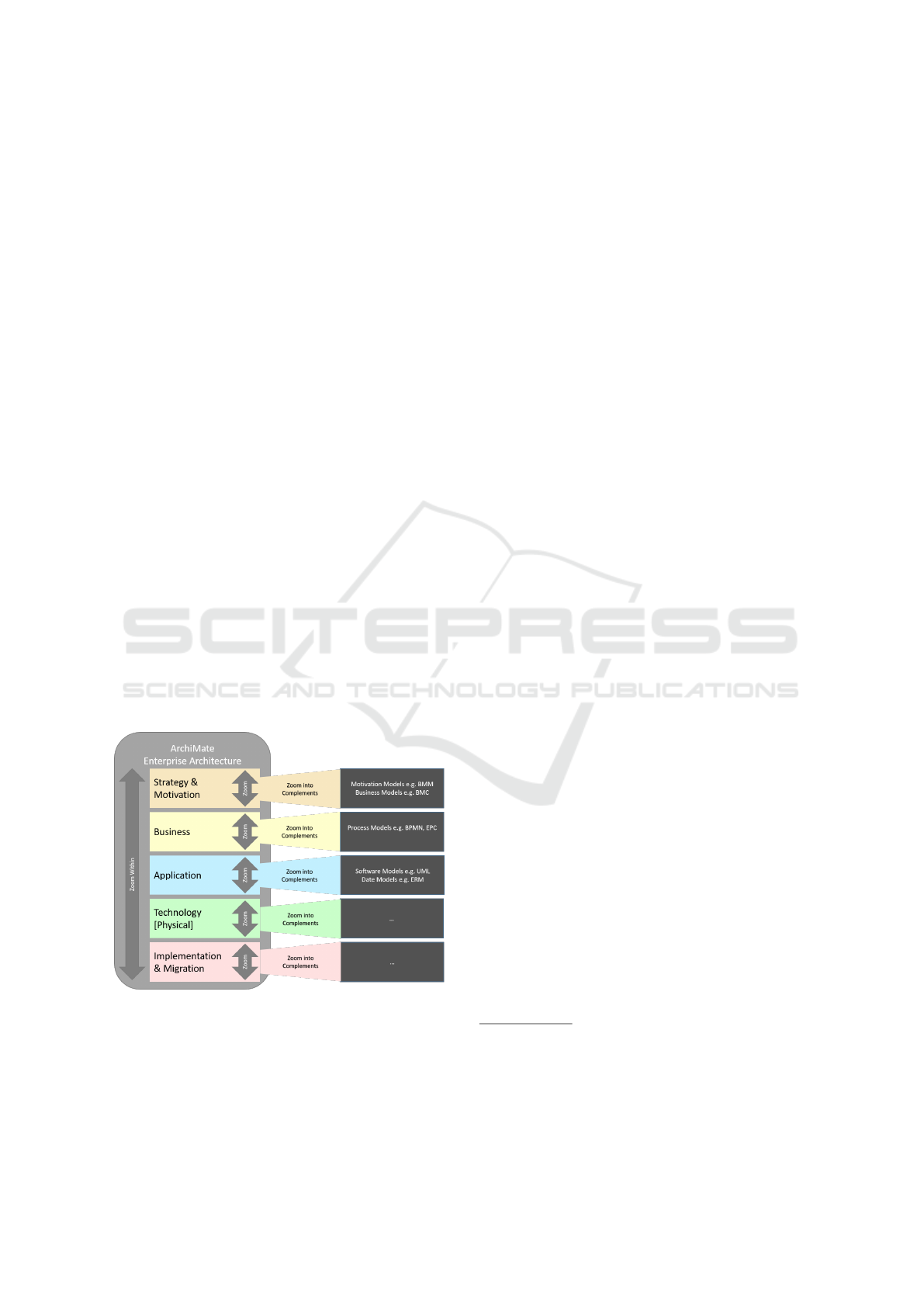
developed concept is shown graphically in Figure 4.
The basis builds the ArchiMate Full Framework with
the different enterprise architecture layers. As view-
based enterprise modeling is widespread and broadly
accepted in the research community as well in prac-
tice, the layers contain the different views and indi-
cate possible entry points of the enterprise map. Two
different zoom principles were considered and named
as ”Zoom Within” and ”Zoom into Complements”.
”Zoom Within” defines the procedure when zoom-
ing within ArchiMate and ”Zoom into Complements”
defines zooming between ArchiMate and other mod-
eling languages that allow modeling specific aspects
like process flows or data structures in more detail.
Figure 4: Overview of the Developed Concept.
In the following, the zoom principles are demon-
strated with examples from the ArchiSurance case
(Jonkers et al., 2019). A prototype of the
ArchiSurance Enterprise Map is available via the fol-
lowing link
3
. All colored or bordered red elements
can be clicked and trigger a certain behavior. The
prototype covers different scenarios, explaining the
idea behind the zoom principles ”Zoom Within” and
”Zoom into Complements”.
Figure 5 shows the prototype with the welcome
page, different enterprise layers, and the correspond-
ing views (number 3). The menu bar (number 1) of-
fers the possibility to set various filters. Elements that
are not interesting for the stakeholder can be hidden.
The ArchiMate relationship tables provide the basis
for which elements can be related to each other. Fur-
thermore, it is possible to apply the derivation rules
for relationships (The Open Group, 2019b). Func-
tions like opening the welcome page or returning to
the previous page, stepping forward (number 2), and
increasing or decreasing the view have been consid-
ered (number 4). Zoom icons enable zooming in and
out of a model (number 5). A minimap helps with
orientation in the enterprise map (number 6). Fur-
ther, users can save the current zoom under favorites
or download it as an enterprise model (number 7).
5.2 Zoom Within
”Zoom Within” describes the zoom behavior between
ArchiMate elements on the same layer and across lay-
ers. The concept is explained using different scenar-
ios. The entry points into the enterprise map built
again the views placed on different enterprise archi-
tecture layers, visualized in Figure 5.
The first elements displayed are those mentioned
in the name of the view. The zoom in is achieved by
clicking on the magnifying glass with a plus symbol
and zoom out by magnifying glass with a minus. The
zoom concept is demonstrated using the stakeholder
view
4
. With a click on stakeholder view, zoom in
is performed, and defined stakeholders are displayed
(see Figure 6a) and build the level 0. Next, elements
that are directly connected to the two stakeholders are
displayed. This corresponds to zoom level 1 visual-
ized in Figure 6b. In this case, five driver elements
are displayed. If it is a nested representation, then the
element which includes nested elements as well the
nested elements are considered as level 0.
3
Link: https://lwqv40.axshare.com. Addi-
tionally, the prototype is preserved on Zenedo
https://doi.org/10.5281/zenodo.5732852 and can be
run locally.
4
This scenario can be seen in the online prototype as
”Scenario1 - Zoom Within”
Enterprise Maps: Zooming in and out of Enterprise Models
519
Figure 5: Prototype Overview.
(a) Stakeholder View - Level 0
(b) Stakeholder View - Level 1
(c) Stakeholder View - Level 2
(d) Stakeholder View - Level 3
Figure 6: Zoom in - Stakeholder View.
The next zoom level shows the elements which
have a direct relation to the elements shown in the
previous level, see Figure 6c. Figure 6d shows the
next zoom level. This can be continued until all ele-
ments are displayed. The entry point is considered as
level 0, and the last level is n. In this scenario, the first
element displayed is ”Stakeholder”, which according
to the ArchiMate metamodel, is also the first element
associated with the core element Motivation. There-
fore, there are no elements above stakeholders. For
this reason, the zoom is arranged in one direction in
this scenario.
At each zoom, the elements are displayed which
have a direct relation to the already displayed ele-
ments, as seen in Figures 6c and 6d. From this, the
first rule is derived:
(R01) At each zoom, the elements are displayed,
which have a direct relation to the already displayed
elements.
The different relationships that ArchiMate model-
ing language has are not prioritized. The second rule
is derived from this fact:
(R02) All relationship types are treated equally.
ArchiMate elements can have multiple relations
to other elements on the same layer and across lay-
ers. Thereby such relations can arise as shown in
the Figure 7. If the first rule is followed, all ele-
ments should be displayed that have a direct relation-
ship to the requirement element ”CRM Data Should
Be Maintained Centrally”. But, other motivation ele-
ments are displayed, followed by strategy elements.
ICEIS 2022 - 24th International Conference on Enterprise Information Systems
520
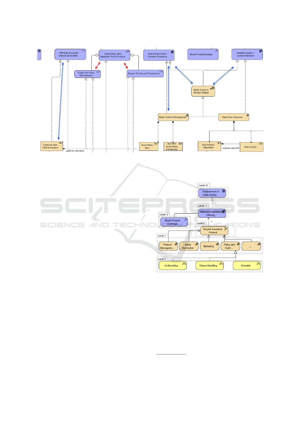
Figure 7: Stakeholder View - Relationship Across Layers.
A distinction is made between layers or element
types, where the relationship between elements of the
same type or the same layer is preferred. Another rule
is derived:
(R03) Relationships between elements of the same
type or layers will be weighted higher than cross-type
or cross-layer relationships.
Another characteristic is the use of transitive
dependencies, which is known especially from
databases. As shown in Figure 7, there is a direct rela-
tionship between strategy element ”Enterprise-Wide
CRM Automation” and motivation element ”CRM
Data Should Be Maintained Centrally” and strategy
element ”Social Media Apps”. This element is in ad-
dition connected to another strategy element, which
is then related to a motivation element. In this case,
there is a sort of transitive dependency with the mo-
tivational elements. From this point of view, another
rule is derived:
(R04) If a transitive dependency exists, the ele-
ment is displayed when the element over which the
transitive dependency exists is revealed.
This means that the strategy element ”Enterprise-
Wide CRM Automation” is only displayed when the
strategy element ”Social Media App” is shown.
In the former scenario, the first element displayed
was on top in the hierarchy. Figure 8 visualizes a sce-
nario where the value stream element ”Aquire Insur-
ance Product” is at level 0. Zoom in will unveil all the
elements on level 1 as well as level -1.
If an element has relations to elements above or
below, then at each zoom, every element, when it is
first displayed, becomes level 0 for itself and applies
the rules for itself at each further zoom. As soon as an
element on level 0 is displayed, which has relations to
elements above or below, a recursion occurs
5
.
Figure 8: Zooming through the Hierarchy.
In order to zoom in and zoom out, it is assumed
that a superior model exists, which consists of Archi-
Mate elements. ArchiMate elements have a relation-
ship to none, one or more other ArchiMate elements.
These can be elements of the same type or layer, a
layer above or a layer below. The reason why an el-
ement is considered to be level 0 lies in the anatomy
of the ArchiMate modeling language. Lankhorst et
al. (Lankhorst et al., 2010) defined three levels to es-
tablish ”a metamodel covering a set of modeling con-
cepts that would allow us to model domains in gen-
5
This scenario can be seen in the online prototype as
”Scenario3 - Zoom Within”
Enterprise Maps: Zooming in and out of Enterprise Models
521
eral”. At level 0, a modeling concept Element was
defined, consisting of a Concept (graphical represen-
tation) and Relations (lines and arrows between the
concepts). In the further development of the Archi-
Made modeling language, the Element, Relationship,
and Relationship Connector were defined as the spe-
cialization of Concept. Structuring information into
clusters and patterns has a significant cognitive im-
pact (Naranjo et al., 2015). For this reason, each zoom
makes sure that elements of the same type are dis-
played first and then cross-layer.
5.3 Zoom into Complements Principle
The ArchiMate language provides a standardized ar-
chitectural modeling concept including their relation-
ships, called ArchiMate metamodel. Figure 9 illus-
trates this concept, where synergies with other mod-
eling languages can be realized in order to provide
detailed information to the consumers of enterprise
models.
Figure 9: Metamodels at different levels of specificity
(Jonkers et al., 2004).
The design of ArchiMate allows a drill down into
domain-specific models and thus offers the possibil-
ity to establish zooming (Jonkers et al., 2004). Archi-
Mate serves as a hub, which is related to the various
domain-specific models (Jonkers et al., 2004). This
concept was the basis for developing the zoom princi-
ple ”Zoom into Complements”, which defines zoom-
ing between ArchiMate and various DSML. Con-
cepts in the ArchiMate language can have a direct
connection to concepts in other DSML (Lankhorst
et al., 2017). In this way, ArchiMate enables different
domain-specific enterprise models to be integrated in
a reasonable way (Lankhorst et al., 2017). The basis
is provided by the mapping between ArchiMate con-
cepts and various DSML.
Table 1 illustrates an example of the mapping be-
tween Business Model Canvas (BMC) concepts and
ArchiMate concepts, where the relation 1:mc can be
associated (Lankhorst et al., 2017). Mapping helps to
establish the relationship between elements of various
DSML and ArchiMate and also to justify it.
Table 1: ArchiMate and BMC.
Business Model Canvas ArchiMate
Key Partner Business Actor (or Role)
Key Activity Capability
Key Resource Resource
Value Proposition Product + Value
Customer Relationship Business Collaboration
Channel Resource (realised by Interface)
Customer Segment Business Actor
Cost Structure Value attached to architecture elements
Revenue Stream Value + Flow
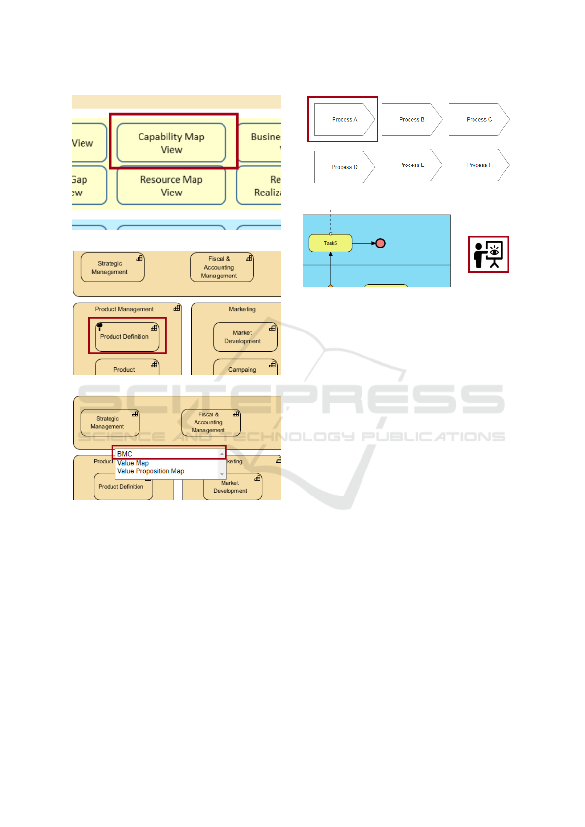
Based an a scenario the navigation from an Archi-
Mate element Capability to BMC is demonstrated
6
.
Entry point is again the view overview, visualized in
Figure 10a. By opening the capability Map view, the
entire content of this view gets visible. If there is a
mapping toward another model, this is indicated by a
pin, depicted in the Figure 10b. With a right-click on
the element, a selection list is displayed, which shows
the DSML to which a relationship exists. Figure 10c
illustrates this behavior.
Another scenario with the business process view
explains a behavior when an ArchiMate element is
mapped to another model and occurs in several pro-
cesses
7
. First, an overview with all affected processes
is shown, and the desired one can be selected, see
Figure 11. Afterward, a dynamic graphical symbol
is displayed, see Figure 12, which indicates that an
overview exists—in this case, a process map with all
processes that have a connection to the initial Archi-
Mate element.
The ArchiMate elements serve as entry points.
The mapping between ArchiMate and DSML is based
on the elements, but an element belongs to a spe-
cific model. For this reason, right-clicking on an el-
ement will not display an element but the relevant
model. Various DSML represents a more detailed
view, which complements the ArchiMate model. For
this reason, the entire domain-specific model is di-
rectly displayed, and zoom in and out of this model
only takes place if a hierarchical representation al-
ready exists. For the process architecture or Value
Proposition Canvas, a zoom function already exist,
which was mentioned in Section 2.
5.4 Zoomability Rules and Metamodel
Figure 13 visualizes the concept of the zoomability
principle as a metamodel. It is assumed that a su-
6
This scenario can be seen in the online prototype as
”Szenario4 - Zoom Complements BMC”
7
This scenario can be seen in the online prototype as”
Scenario5 - Zoom ComplementsBPMN”
ICEIS 2022 - 24th International Conference on Enterprise Information Systems
522
(a) Entry Point into the Enterprise Map
(b) Pin indicates Mapping
(c) Mapped Models get visible
Figure 10: Zoom in - Capability Map View.
perior model exists, which is defined by ArchiMate
concepts. The ArchiMate concepts, in turn, consists
of ArchiMate elements. Those are specialized by:
(1) top ArchiMate elements, (2) same level Archi-
Mate elements, and (3) below ArchiMate elements.
ArchiMate elements are associated with none, one or
more models. Those models are expressed by var-
ious DSML and consist of DSML elements. The
ArchiMate elements are mapped to none, one or more
DSML elements. The zoomability principle is spe-
cialized by ”Zoom Within” and ”Zoom into Comple-
ments”. Zoomability of the superior model is defined
by zoomability within and of models by ”Zoom into
Complements”. ArchiMate itself is a DSML, which
Figure 11: Overview of the affected processes.
Figure 12: Dynamic Graphical Symbol.
can represent the Enterprise Architecture (Lankhorst
et al., 2010). The metamodel implies a relationship
between ArchiMate and various other DSML.
During the development of the artifact, rules were
defined, which contributed to a generic approach and
allowed an application to another case. The derivation
of the rules as explained in Section 5.2. Summarized
are the four rules that have been defined:
• (R01) At each zoom, the elements are displayed,
which have a direct relation to the already dis-
played elements.
• (R02) All relationship types are treated equally.
• (R03) Relationships between elements of the
same type or layers will be weighted higher than
cross-type or cross-layer relationships.
• (R04) If a transitive dependency exists, the ele-
ment is displayed when the element over which
the transitive dependency exists is revealed.
6 EVALUATION OF THE
DEVELOPED CONCEPT
As the development of the artifact is novel, the real-
ization is shown employing a demonstration (Vaish-
navi and Kuechler, 2015). For this purpose, a set
of different situations, which may occur in practice,
were defined. A prototype was created to demonstrate
that the solution can be applied to those situations.
For the evaluation of the developed solution, another
case, ArchiMetal (Band et al., 2019) was used as a
basis.
Enterprise Maps: Zooming in and out of Enterprise Models
523
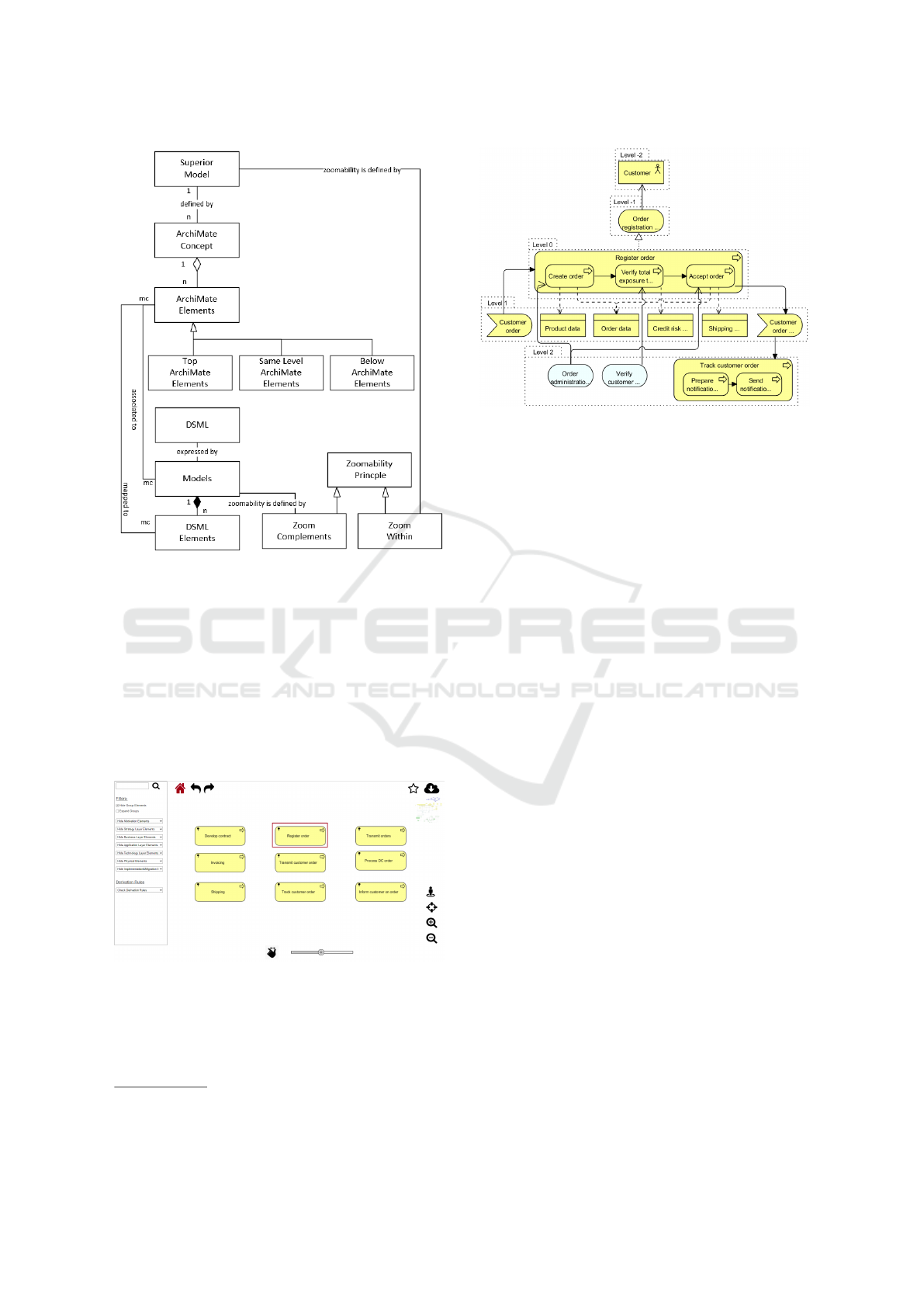
Figure 13: Metamodel of the Proposed Solution.
First, the ”Zoom Within” principle is evaluated
8
.
All the zoom levels of the ArchiMetal case were de-
fined, and this corresponds to the ”Superior Model”
defined in the metamodel of the proposed solution in
Figure 13. As a persona, a Process Owner was cho-
sen, who is interested in examining the relationships
of the process ”Register Order”. The overview of all
views serves as an entry point, see Figure 5. The
Business Process Map View shows an overview of the
business process of the organization, see Figure 14.
Figure 14: Business Process Map View.
Since it is a nested representation and the process
”Register order” is composed of three subprocesses,
these are also revealed directly. Figure 15 shows the
different levels. The first two zoom levels show the
8
This scenario can be seen in the online prototype as
”Evaluation-Scenario1 - Process”
Figure 15: Evaluation of the Zoomability Principle.
principle and application of the defined rules. With
each zoom, more and more elements are displayed
while the type of the relation is treated equally ac-
cording to the rule R02. Table 16 explains which ele-
ments appear at which zoom level. On the zoom level
0, there is the main process ”Register order” and the
three sub processes ”Create order, Verify total expo-
sure to customer, Accept order”, so four elements in
total. For each of the four elements, the defined rules
in Section 5.4 are applied. Element ”Register order”
directly relates to the top ArchiMate element ”Order
registration service” which corresponds to level -1.
The same rule can also be applied to the represen-
tation of the element ”Customer order”, which then
corresponds to level 1, also to below ArchiMate el-
ement. This procedure is repeated until all elements
included in the superior model are displayed.
The zoom principle puts the element in the fore-
ground therefore, the element which is subject to a
transitive dependency is displayed after the element
over which this dependency is present. Therefore not
only the relationship between the elements is shown
while zooming, but the element itself and its relation-
ship to the already visible elements. The same proce-
dure is applied to the three other elements, which are
on level 0. Whit the next zoom, all the elements which
have been added before on level -1 and level 1 be-
come level 0, and the defined rules are applied again.
Table 16 visualizes the appearance of the recursion.
The rule R03 is taken into account, and elements from
other layers are only displayed if no other elements of
the same layer can be displayed, like demonstrated
with the application service elements ”Order admin-
istration service” and ”Verify customer exposure ser-
vice” in Figure 15.
After the application of ”Zoom Within” has been
demonstrated within an example using a prototype,
the applicability of ”Zoom into Complements” is be-
ICEIS 2022 - 24th International Conference on Enterprise Information Systems
524
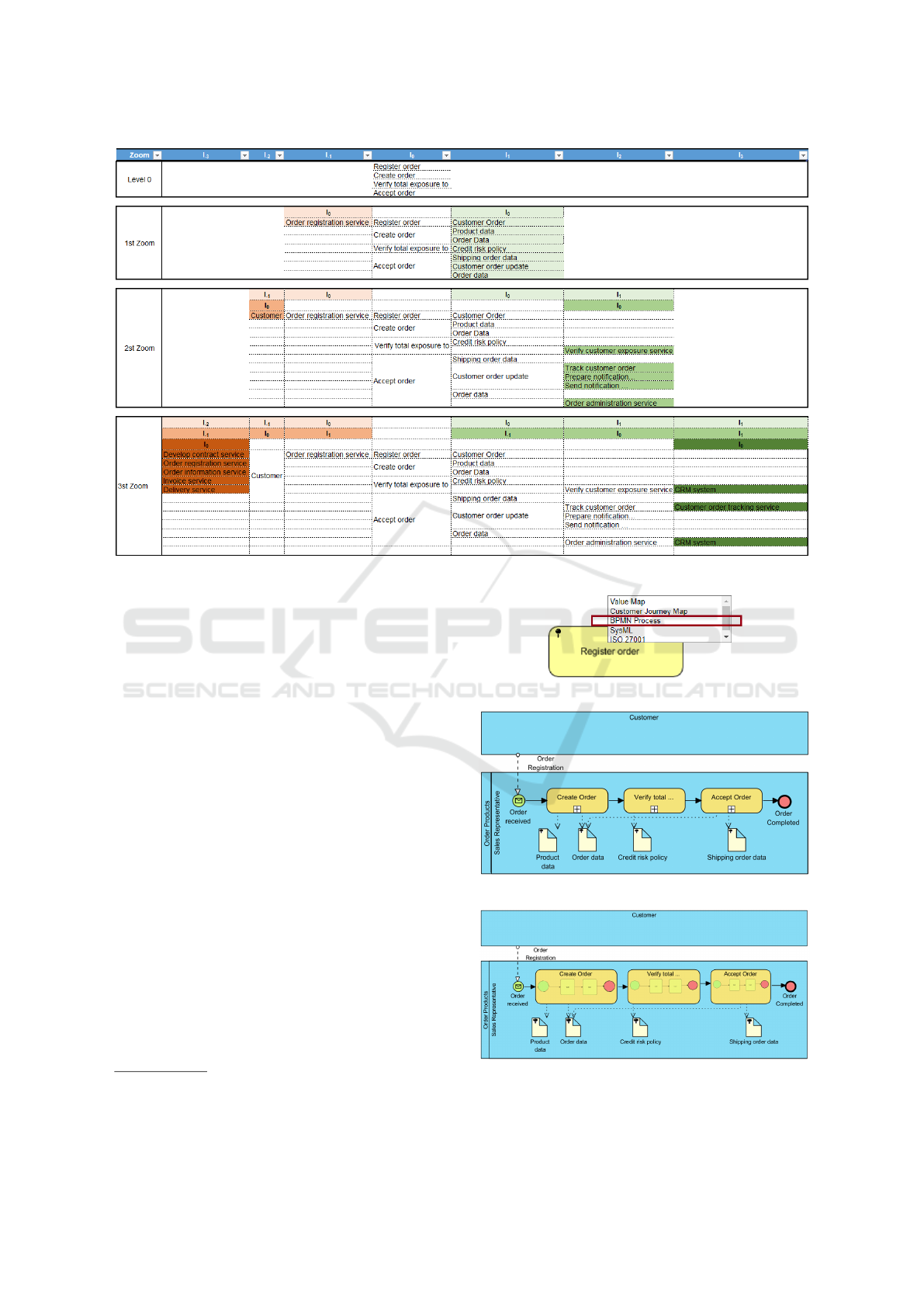
Figure 16: Zoom Levels Explained.
ing evaluated. Using scenarios
9
a prototype was built,
which demonstrates the procedure. The entry point
into the enterprise map is the view overview visual-
ized in Figure 5. A pin sign on process ”Register
order” indicated a mapping to another modeling lan-
guage, visualized in Figure 17a. In this example, the
BPMN process is selected and the process modeled
according to the notation BPMN 2.0 is displayed in-
dicated in Figure 17b. If a zoom option exists for the
displayed model, as in process architecture, then the
level of detail can be adjusted. In this example, the
sub-processes are expanded visualized in Figure 17c.
Further, if a mapping to another language exists, in
this case, data objects indicated a mapping, detailed
zoom can be applied.
The developed concept was applied to a new sit-
uation and it was demonstrated that the zoomability
concept has a general approach, and reveals the con-
nection between the models on different degree of de-
tail. Further, the evaluation showed the applicability
of the defined rules and the metamodels.
9
This scenario can be seen in the online prototype as
”Evaluation-Scenario3 - Complements ProcessView” and
”Evaluation-Scenario4 - Complements Motivation”
(a) Zoom into BPMN Process Model
(b) Zoom into BPMN Process Model
(c) Zoom into BPMN Process Model
Figure 17: Zoom in - Capability Map View.
Enterprise Maps: Zooming in and out of Enterprise Models
525

7 CONCLUSIONS
The main contribution is a development of a zooma-
bility concept that allows stakeholders to see relation-
ships across views and to enrich the view with more
detailed models. The developed concept offers the
possibility to see the possible impact of a change from
a dedicated view by using the zoom levels. A widely
accepted standard was used as a basis, and rules were
defined on how to implement the zoomability princi-
ple. The rules serve to represent a hierarchical output
of zoom levels. The metamodel is generic and can
be implemented in various EA tools. The concept of-
fers a good basis to be equipped with further naviga-
tion features. For example, the possibility to compare
baseline and target architecture, building own views,
set focus, or further features. Several possible naviga-
tion features were defined in the prototype
10
, which
need to be developed further.
REFERENCES
Ahlemann, F., Stettiner, E., Messerschmidt, M., and Leg-
ner, C. (2012). Strategic enterprise architecture man-
agement: challenges, best practices, and future develop-
ments. Springer Science & Business Media.
Band, I., Bjekovi
´
c, M., Else, S., Kroese, R., and Lankhorst,
M. (2019). The archimetal case study. online.
Bjekovic, M., Proper, H. A., and Sottel, J.-S. (2012). To-
wards a coherent enterprise modelling landscape. In
Short Paper Proceedings of the 5th IFIP WG 8.1 Work-
ing Conference on the Practice of Enterprise Modeling.
CEUR Workshop Proceedings, Vol-933.
Bork, D. and Alter, S. (2018). Relaxing modeling criteria
to produce genuinely flexible, controllable, and usable
enterprise modeling methods. In EMISA, pages 46–50.
Desfray, P. and Raymond, G. (2018). TOGAF, Archimate,
UML et BPMN-3e
´
ed. Dunod.
Dumas, M., La Rosa, M., Mendling, J., and Reijers, H. A.
(2013). Business process management. Springer.
Hinkelmann, K., Gerber, A., Karagiannis, D., Thoenssen,
B., Van der Merwe, A., and Woitsch, R. (2016). A new
paradigm for the continuous alignment of business and
it: Combining enterprise architecture modelling and en-
terprise ontology. Computers in Industry, 79:77–86.
ISO 42010 (2011). Systems and software engineering
— Architecture description. International Organiza-
tion for Standardization. https://www.iso.org/standard/
50508.html; Accessed July 12, 2020.
Javed, A., Azam, F., and Umar, A. (2015). Model driven
upstream and downstream artifacts. Procedia Computer
Science, 64:514–520.
10
See online prototype ”Navigation Features - ...”
Jonkers, H., Band, I., Quartel, D., and Lankhorst, M.
(2019). The archisurance case study. online.
Jonkers, H., Lankhorst, M., Van Buuren, R., Hoppenbrouw-
ers, S., Bonsangue, M., and Van Der Torre, L. (2004).
Concepts for modeling enterprise architectures. Inter-
national Journal of Cooperative Information Systems,
13(03):257–287.
Lankhorst, M. et al. (2017). Enterprise architecture at work.
Springer, 4 edition.
Lankhorst, M., Proper, H. A., and Jonkers, H. (2010).
The anatomy of the archimate language. International
Journal of Information System Modeling and Design
(IJISMD), 1(1):1–32.
Naranjo, D., S
´
anchez, M. E., and Villalobos, J. (2015).
Evaluating the capabilities of enterprise architecture
modeling tools for visual analysis. Journal of Object
Technology, 14(1).
Osterwalder, A., Pigneur, Y., Bernarda, G., and Smith, A.
(2014). Value Proposition Design - How to Create Prod-
ucts and Services Customers Want. John Wiley & Sons.
Rehring, K. and Ahlemann, F. (2020). Evaluating the user
experience of an augmented reality prototype for enter-
prise architecture. In 15th International Conference on
Wirtschaftsinformatik.
Rehring, K., Br
´
ee, T., Gulden, J., and Bredenfeld, L. (2019).
Conceptualizing ea cities: Towards visualizing enterprise
architectures as cities. In European Conference on Infor-
mation Systems ECIS.
Sandkuhl, K., Stirna, J., Persson, A., and Wißotzki, M.
(2014). Enterprise modeling. Springer.
The Open Group (2018). The TOGAF
R
standard, version
9.2.
The Open Group (2019a). Archimate 3.1 Specification.
http://pubs.opengroup.org/architecture/archimate3-doc.
The Open Group (2019b). ArchiMate
R
3.1 Specification.
Van Haren.
Vaishnavi, V. K. and Kuechler, W. J. (2015). Design science
research methods and patterns: innovating information
and communication technology. CRC Press Taylor &
Francis Group, 2nd edition.
Van der Torre, L., Lankhorst, M., ter Doest, H., Camp-
schroer, J. T., and Arbab, F. (2006). Landscape maps for
enterprise architectures. In International Conference on
Advanced Information Systems Engineering, pages 351–
366. Springer.
Vernadat, F. (1996). Enterprise modeling and integration.
Chapman & Hall.
Vernadat, F. (2014). Enterprise modeling in the context of
enterprise engineering: State of the art and outlook. In-
ternational Journal of Production Management and En-
gineering, 2(2):57–73.
Zachman, J. A. (2016). The framework for enterprise archi-
tecture: Background, description and utility.
ICEIS 2022 - 24th International Conference on Enterprise Information Systems
526
