
Offline Mining of Microservice-based Architectures
Jacopo Soldani
a
, Javad Khalili, and Antonio Brogi
b
Department of Computer Science, University of Pisa, Pisa, Italy
Keywords:
Microservices, Microservices Architecture, Software Architecture Mining.
Abstract:
Designing, implementing, and operating microservices is known to be complex and costly, mainly due to the
multitude of heterogeneous software services forming a microservice-based application. Such tasks can be
simpler if a specification of the microservice-based architecture (MSA) of an application is available. At the
same time, due to the number of services and service interactions in a MSA, manually generating a specifi-
cation of such MSA is complex and costly. For this reason, in this paper we present a novel technique for
automatically mining the specification of a MSA from its Kubernetes deployment. The obtained MSA speci-
fication is in µTOSCA, a microservice-oriented profile of the human- and machine-readable OASIS standard
TOSCA. We also present a prototype implementation of our technique, which we use to assess it by means of
case studies based on third-party applications.
1 INTRODUCTION
Microservice-based architectures (MSAs) are known
to enable realising so-called cloud-native applica-
tions, viz., applications architected to fully exploit the
potentials of cloud computing platforms (Kratzke and
Quint, 2017). This resulted in MSAs becoming com-
monplace. For instance, Amazon, Netflix, or Twit-
ter are already exploiting MSAs to deliver their busi-
nesses (Soldani et al., 2018).
MSAs are essentially service-oriented architec-
tures satisfying some additional key design principles,
e.g., ensuring services’ independent deployability and
horizontal scalability, or isolating failures (Zimmer-
mann, 2017). It is hence crucial to determine whether
a service-based application adheres to the key design
principles of MSAs, and understanding how to refac-
tor an application to resolve possible violations of
such key design principles (Soldani et al., 2021).
µTOSCA and µFRESHENER (Brogi et al., 2020)
enable modelling, analysing, and refactoring the ar-
chitecture of a service-based application, to enhance
its adherence to the key design principles of MSAs.
µTOSCA is a model enabling to specify MSAs
with the human- and machine-readable OASIS stan-
dard TOSCA (OASIS, 2020). MSAs are represented
by typed directed graphs, called topology graphs,
where nodes model the services, integration compo-
a
https://orcid.org/0000-0002-2435-3543
b
https://orcid.org/0000-0003-2048-2468
nents (e.g., load balancers or message queues), and
databases forming a MSA. Oriented arcs represent the
interactions among such components.
µFRESHENER (Brogi et al., 2020) enables visu-
alising the µTOSCA specification of an MSA, and
automatically analysing the specified MSA to check
whether the application includes some known archi-
tectural smells, viz., possible symptoms of violations
of the key design principles of MSAs. µFRESHENER
also enables reasoning on how to refactor an appli-
cation to resolve identified architectural smells, based
on applying practitioner-shared refactorings known to
resolve their occurrence (Neri et al., 2020).
On the other hand, MSAs can often include hun-
dreds of interacting services (Forti et al., 2022). This
makes manually specifying MSAs in µTOSCA a
complex, time-consuming, and error-prone process
(Soldani et al., 2021). To this end, µMINER (Muntoni
et al., 2021) was proposed to automatically mine the
µTOSCA specification of the MSA of an application,
given the latter’s Kubernetes deployment. µMINER
first elicits the services, integration components, and
databases in an MSA from the deployment specifica-
tion in Kubernetes. It then runs the application de-
ployment on a devoted cluster, and it loads the de-
ployed application. µMINER also sniffs the packets
exchanged among the deployed application compo-
nents to mine the occurring interactions. This requires
µMINER to run with root privileges on the cluster, and
the application to not encrypt any of the messages ex-
Soldani, J., Khalili, J. and Brogi, A.
Offline Mining of Microservice-based Architectures.
DOI: 10.5220/0011061000003200
In Proceedings of the 12th International Conference on Cloud Computing and Services Science (CLOSER 2022), pages 63-73
ISBN: 978-989-758-570-8; ISSN: 2184-5042
Copyright
c
2022 by SCITEPRESS – Science and Technology Publications, Lda. All rights reserved
63
changed among deployed components, which can of
course happen only in a testing environment. The
deployed application must also be loaded to stress
all possible service interactions, to allow µMINER
to monitor them. In short, µMINER requires to run
the target microservice-based application in a suitably
configured testing environment.
In this paper, we propose a different technique
for mining the µTOSCA specification of the MSA
of an application, which can work with any existing
application deployment, rather than requiring a suit-
ably configured testing environment. Our technique
starts from the Kubernetes deployment of an appli-
cation, configured to also exploit Istio
1
and Kiali
2
,
two Kubernetes-native tools for proxying deployed
services and monitor their interactions. It then pro-
cesses, offline, the Kubernetes manifest files speci-
fying the application deployment and the Istio-based
proxying of its services, as well as a graph generated
by Kiali in any former run of the application, e.g., its
production run. The Kiali graph models the deployed
software components (as nodes) and their monitored
interactions (as oriented arcs). Given such inputs,
our technique can automatically mine the MSA of
an application in two steps. It first elicits the soft-
ware components and their interactions, producing a
first draft of the MSA of an application. The draft is
then refined by distinguishing services from integra-
tion components and databases, and by characteris-
ing the mined interactions, e.g., determining whether
circuit breakers or timeouts are used therein. The re-
fined architecture is finally marshalled to µTOSCA,
obtaining a specification which can be processed by
µFRESHENER.
To illustrate the feasibility of the proposed min-
ing technique, we present an open source proto-
type implementation, called µTOM (µTOSCA Of-
fline Miner). We also show how we used µTOM to
run case studies based on two existing, third-party ap-
plications, viz., Robot Shop (Instana, 2021) and On-
line Boutique (Google Cloud, 2021). The case studies
show that µTOM effectively mines the MSAs of the
considered applications, and that it also captures more
details if compared with µMINER.
The paper is organised as follows. Section 2 provides
the necessary background on µTOSCA, Kubernetes,
Istio, and Kiali. Section 3 presents our technique for
mining MSAs offline, while Section 4 introduces its
open source prototype implementation. Section 5 il-
lustrates the case studies assessing our technique. Fi-
nally, Sections 6 and 7 discuss related work and draw
some concluding remarks, respectively.
1
https://istio.io.
2
https://kiali.io.
2 BACKGROUND
We hereafter provide the necessary background on
µTOSCA (Section 2.1), Kubernetes (Section 2.2),
and Istio and Kiali (Section 2.3).
2.1 µTOSCA
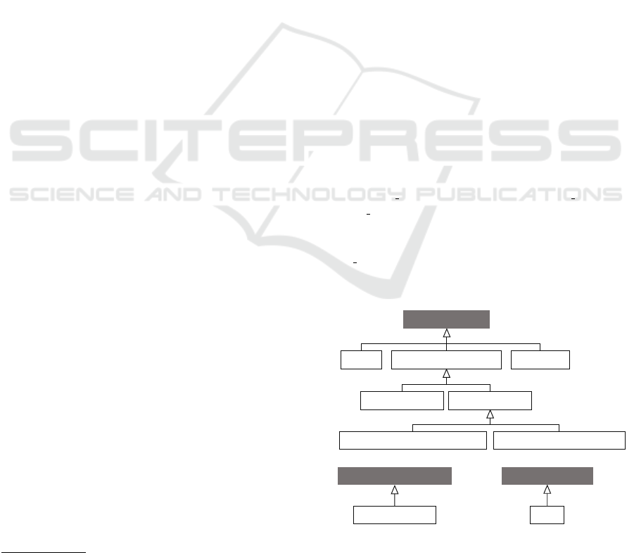
The µTOSCA type system (Figure 1) allows specify-
ing MSAs as typed topology graphs in TOSCA, the
Topology and Orchestration Specification for Cloud
Applications (OASIS, 2020). Topology nodes model
the services, communication patterns, or databases in
an MSA. A Service runs some business logic, e.g.,
a service managing users’ orders in an e-commerce
application. A CommunicationPattern implements
message-based integration pattern (Hohpe and Woolf,
2003), viz., MessageRouter and MessageBroker,
which decouples the communication among two or
more components. MessageBrokers are also distin-
guished based on whether they implement message
brokering asynchronously (AsynchronousMessage-
Broker) or synchronously (SynchronousMessage-
Broker). Finally, a Database is a component stor-
ing the data pertaining to a certain domain, e.g., a
database of orders in an e-commerce application.
Topology arcs instead model the interactions
among the components in an MSA, throughout Inte-
ractsWith relationships. Such relationships can be fur-
ther characterized by setting three boolean properties,
viz., circuit breaker, timeout, and dynamic discovery.
circuit breaker, timeout allows specifying whether the
source node is interacting with the target node via a
circuit breaker or by setting proper timeouts. dyna-
mic discovery instead allows to specify whether the
endpoint of the target of the interaction is dynamically
discovered (e.g., by exploiting a discovery service).
Service Database
MessageRouter
AsynchronousMessageBroker SynchronousMessageBroker
InteractsWith Edge
micro.nodes.Root
CommunicationPattern
MessageBroker
micro.relationships.Root micro.groups.Root
Figure 1: The node types, relationship types, and group
types defining µTOSCA. The corresponding definitions
in TOSCA are publicly available on GitHub at https://
di-unipi-socc.github.io/microTOSCA/microTOSCA.yml.
CLOSER 2022 - 12th International Conference on Cloud Computing and Services Science
64
Finally, nodes can be added to an Edge group.
The latter specifies the application components that
are publicly accessible from outside of the applica-
tion, namely those components that can be directly
accessed by external clients.
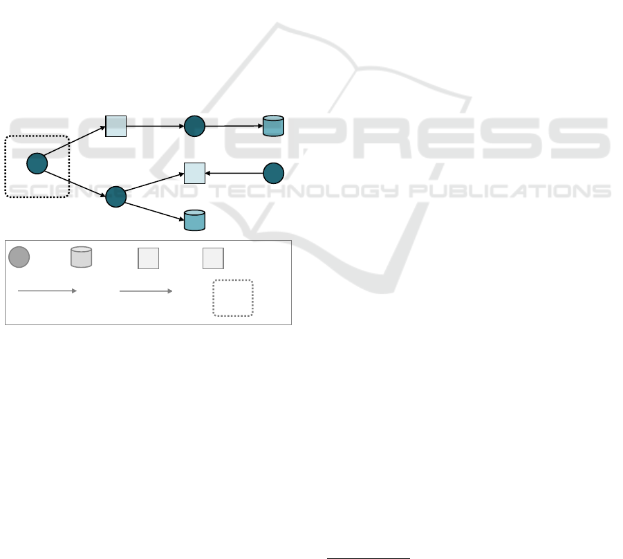
Example. Figure 2 displays an example of µTOSCA
topology modelling the MSA of a toy e-commerce ap-
plication. The application includes four services, i.e.,
frontend (accessible by external clients), orders, pay-
ment, and shipping. It is then completed by two in-
tegration components, i.e., router and queue, and two
databases, i.e., catalogDb and ordersDb. The frontend
allows browsing the catalogue of available products,
by interacting with catalog. The actual instance of
catalog used to access the catalogDb is dynamically
discovered by a message router implementing server-
side service discovery. The frontend also allows to
place orders, by interacting with orders. The latter al-
lows to upload new product orders, which are stored
in ordersDb, and which are also enqueued in the asyn-
chronous message broker implementing the queue of
orders to be shipped. The latter is consumed by the
service shipping, which pulls orders from the queue
and proceeds with their shipping.
mB
mR
edge
frontend
ordersDb
router
queue shipping
c
Service
mR
Message
Router
mB
Asynchronous
MessageBroker
Database
InteractsWith
InteractsWith
(circuit_breaker set)
c
Edge
orders
catalogDb
catalog
Legend
Figure 2: An example of µTOSCA topology modelling the
architecture of an application.
2.2 Kubernetes
Kubernetes allows deploying and managing multi-
service applications in distributed clusters. Such a de-
ployment and management is realised by orchestrat-
ing pods, which constitute Kubernetes’ deployment
units. A pod is a deployable instance of an application
service, which is shipped within a single container or
in several tightly coupled containers. A pod can actu-
ally encapsulate multiple Docker containers that need
to share the same resources, e.g., when a container-
ised service is accompanied by “sidecar” containers
monitoring it or proxying its communications.
Pod instances are deployed and managed with Ku-
bernetes controllers. The latter allow to spawn and
manage pod instances from pod templates, which are
included in workload resource specifications, e.g.,
Deployments, StatefulSets, and ReplicaSets. The lat-
ter specify the Docker containers running in a pod,
their target state, as well as the number of replicas of
the pod that must be deployed. Kubernetes controllers
then ensure that the specified number of replicas of a
pod continue to run on a cluster, with each pod in-
stance reaching and maintaining its target state.
Replicated pods can be accessed through Kuber-
netes services, which define their load balancing poli-
cies. A Kubernetes service indeed implements a mes-
sage routing component, which receives requests and
balances them among the pods it manages accord-
ing to the specified balancing policy. Kubernetes ser-
vices can be of multiple types, depending on whether
they should be accessible only within the Kubernetes
cluster (viz., ClusterIP services), or whether they
should be exposed to external clients (viz., NodePort
or LoadBalancer services).
2.3 Istio and Kiali
Istio and Kiali are two Kubernetes-native tools for
controlling and monitoring service interactions. Is-
tio includes so-called envoy proxies in a Kubernetes
deployment. Envoy proxies are deployed as sidecar
proxies alongside application services to control how
they interact with each other. This is done by spec-
ifying VirtualServices or DestinationRules, which al-
low defining how to route a message to its destination.
This includes, e.g., indicating whether timeouts or cir-
cuit breakers are used to avoid the sender to continue
waiting for an answer when the receiver has failed.
Kiali is an observability console, which comes na-
tively integrated with Istio. It exploits Istio envoy
proxies to store the interactions they proxy, so as to
trace the interactions among deployed services. Each
interaction is stored together with its metadata, in-
cluding the source and target Kubernetes workloads
or services, and whether the interaction successfully
completed. Kiali then exploits such interactions to
build different types of graphs, which enable visual-
ising them at different abstraction levels in the Kiali
dashboard, and which can be exported to JSON graph
data files. In the rest of this paper, we consider Kiali
graph modelling monitored service interactions, viz.,
service graphs.
3
3
https://kiali.io/docs/features/topology
Offline Mining of Microservice-based Architectures
65
topology
graph
Kubernetes
manifest files
Mining Topology Fragments Node Refinement
Kiali graph
(existing) app deployment
YAML
JSON
mR
edge
μTOSCA
refined
topology
graph
mR mB
μTOSCA
edge
Connecting Topology Fragments
mR
edge
μTOSCA
Interaction Refinement
mR mB
d c
t
t
μTOSCA
edge
Step 1: Mining
Step 2: Refinement
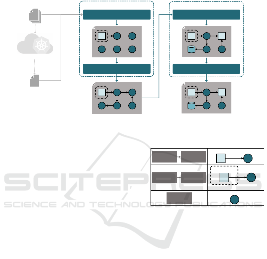
Figure 3: Our two-steps technique for mining MSAs from their Kubernetes deployment.
3 MINING MSAs
Our technique for mining MSAs consists of a pipeline
of two steps (Figure 3), which processes the Kuber-
netes manifest files specifying the application deploy-
ment and a JSON graph data file specifying the graph
generated by Kiali while monitoring an existing ap-
plication deployment. Such inputs are first processed
by the mining step, which elicits the nodes and inter-
actions forming the target MSAs, and which produces
a first corresponding µTOSCA topology graph. The
graph is then passed to the refinement step, which dis-
tinguishes the types of the nodes therein, and which
characterises the mined relationships by indicating
whether dynamic discovery, circuit breakers, or time-
outs are used in the corresponding interactions.
3.1 Step 1: Mining
The mining step processes the available inputs to de-
termine the nodes and interactions forming the tar-
get MSA. Firstly, µTOSCA topology fragments are
mined from the Kubernetes manifest files, by es-
sentially mapping Kubernetes entities to µTOSCA
nodes. The topology graph is then completed by con-
necting mined topology fragments based on the run-
time interactions contained in the Kiali graph.
Mining Topology Fragments. Topology fragments
are extracted from the Kubernetes manifest files by
first mapping the workloads and services specified
therein to µTOSCA nodes. Each Kubernetes work-
load specifies the pod configuration for a component
of the target MSA, by indicating the Docker container
mR
edge
frontend
orders.svc
orders
orders.svc
(ClusterIP)
orders
(Deployment)
frontend.svc
(NodePort)
frontend
(Deployment)
(b)
(c)
Kubernetes μTOSCA
(a)
queue
(Deployment)
queue
mR
frontend.svc
Figure 4: Three examples of µTOSCA topology fragments
mined from Kubernetes services and workloads.
from which it runs and its target configuration (Sec-
tion 2.2). Therefore, each Kubernetes workload is
mapped to a µTOSCA node of type Service. The type
may change in the refinement step, if the workload is
used to deploy an integration component or database.
A Kubernetes service instead implements a mes-
sage routing component balancing the traffic sent to
the replicas of the pod they manage, specified by a
Kubernetes workload (Section 2.2). They are hence
mapped to µTOSCA nodes of types MessageRouter,
which are directly specified to InteractsWith the Servi-
ce node corresponding to the workload they manage.
In addition, if a Kubernetes service is specified to be a
NodePort or LoadBalancer, its corresponding Messa-
geRouter node is placed within the Edge group. This
reflects the fact that NodePort or LoadBalancer ser-
vices that can be invoked by external clients.
Figure 4 illustrates three examples of application
of our topology fragment mining. In case (a), a Ku-
bernetes ClusterIP service orders.svc manages the
CLOSER 2022 - 12th International Conference on Cloud Computing and Services Science
66

Deployment workload running the service orders. By
applying our node mining technique, we obtain a
MessageRouter node modelling the Kubernetes ser-
vice, which InteractsWith the Service node modelling
the workload. Case (b) is similar, with the only dif-
ference that the MessageRouter node is placed in the
Edge group, since Kubernetes NodePort services are
exposed to external clients, while the same does not
hold for ClusterIP services. Finally, case (c) con-
siders a Deployment workload used to deploy a mes-
sage queue, without any Kubernetes service balacing
its load. In this case, we obtain a singleton Service
node. Case (c) also provides an example of µTOSCA
node that may be typed as Service only temporarily:
the type of queue might be changed to Asynchrono-
usMessageBroker, if it actually implements an asyn-
chronous message broker (Section 3.2).
Connecting Topology Fragments. The topology
fragments obtained by parsing the Kubernetes man-
ifest files are interconnected to model the runtime
interactions occurring among the components they
model. This is done by parsing the Kiali graph,
which explicitly models the component interactions
that were monitored in a former deployment of the
application, e.g., in its production deployment.
A monitored interaction is represented as an edge
in the Kiali graph, which connects the node corre-
sponding to the the Kubernetes workload that started
the interaction to the Kubernetes service that was in-
voked.
4
Each edge is hence mapped to InteractsWith
relationships connecting the Service node modelling
the starting workload to the MessageRouter node
modelling the target Kubernetes service. In addition,
the mined InteractsWith relationship are directly set to
enact dynamic
discovery, given that Kubernetes pre-
scribes to invoke services based on their name and to
rely on Kubernetes’ native DNS to resolve the address
of the actual host to contact.
Figure 5 illustrates an examples of mined Inte-
ractsWith relationship, which connects two of the
topology fragments in Figure 4. The Kiali graph spec-
ifies that the Kubernetes workload running the fron-
tend service interacted with the Kubernetes service
managing the replicated orders service. This is mod-
elled by including an InteractsWith relationship con-
necting the corresponding µTOSCA nodes, viz., the
Service frontend and the MessageRouter orders.svc.
4
Kiali unifies a Kubernetes service with the Kubernetes
worklaod it manages, assuming that Kubernetes services
are used to enact server-side service discovery, as recom-
mended by Kubernetes documentation (https://kubernetes.
io/docs/concepts/services-networking/service).
edge
frontend
orders.svc
orders
mR
frontend.svc
Kiali μTOSCA
frontend
orders
mR
d
Figure 5: Examples of µTOSCA InteractsWith relationship
mined from the Kiali graph.
3.2 Step 2: Refinement
The mining step produces a “draft” of the µTOSCA
topology modelling the target MSA, in which all
nodes and interactions are recognised, but associated
with default types and properties.
Node Refinement. After the mining step, nodes
are associated with either one of two types: Messa-
geRouter or Service. Whilst nodes types as Messa-
geRouter are truly routing messages in the Kuber-
netes deployment of an MSA (being them obtained
from Kubernetes services), Service is used as the de-
fault type for all other nodes. Nodes initially typed
as Services may however implement other compo-
nents than those running some business logic, namely
databases or asynchronous message brokers. The ob-
jective of the node refinement substep is hence to
identify such nodes and assign them with the corre-
sponding µTOSCA type, viz., Database and Asynch-
ronousMessageBroker.
Database and message brokers can be seen as
“passive” components: despite they reply when being
invoked by other components, they are not proactively
invoking other components (Soldani et al., 2021).
They hence appear as “sink nodes” in the mined
µTOSCA topology graph, meaning that they are tar-
geted by InteractsWith relationships, whilst no such
relationship outgoes from them. The node refinement
substep hence focuses on the Service nodes being sink
nodes, and determines whether they should be rather
typed as Database or AsynchronousMessageBroker.
This is essentially done by looking at the Docker im-
age running in the corresponding Kubernetes work-
load: if such image is one of the official Docker im-
ages for databases or message brokers (Table 1), then
the node’s type is changed to Database or Asynch-
ronousMessageBroker, respectively. Otherwise, the
node continues to be a Service.
As a result, there might be nodes typed as Servi-
ces, despite they are implementing some databases or
message brokers by means of unofficial Docker im-
ages. If this is the case, the application developer can
Offline Mining of Microservice-based Architectures
67

refine the generated µTOSCA representation of the
target MSA by suitably changing their types. To sup-
port this, the implementation of our technique (which
we describe in Section 4) not only features the fully
automated mode described above, but also an inter-
active mode prompting developers when a sink node
may implement something different from a Servi-
ce. This enables them to explicitly indicate whether
such node should be typed as Service, Database, or
AsynchronousMessageBroker.
Interaction Refinement. The interaction refinement
substep is intended to characterise mined interactions
by associating them with other properties than the
default dynamic discovery property included during
the mining step. More precisely, it associates each
mined InteractsWith relationship with properties cir-
cuit breaker and timeout, if a circuit breaker or a
timeout is used during the corresponding interactions.
This is done by inspecting the Istio traffic manage-
ment rules defined for the service targeted by each
mined InteractsWith relationship.
Istio traffic management rules are defined in
VirtualServices and DestinationRules (Section 2.3).
VirtualServices allow explicitly setting a timeout
field to indicate the maximum amount of time after
which the interaction with the target service is con-
sidered to have failed (Figure 6a). DestinationRules
instead feature a field outlierDetection that allows
defining circuit breaking policies, by setting the max-
imum number of tolerated consecutive errors before
the circuit breaker trips, as well as the amount of time
it remains tripped (Figure 6b).
The interaction refinement substep hence checks
whether VirtualServices or DestinationRules are de-
fined for the target of each interaction. To avoid un-
necessarily browsing the input Kubernetes manifest
files, it relies on the metadata included in the Kiali
graph. Kiali indeed already determines whether the
target of an interaction is reached through a Virtual-
Service or through a DestinationRule defining some
circuit breaking policy. If this is the case, Kiali asso-
ciates the service targeted by a monitored interaction
with properties hasVS or hasCB, respectively. There-
fore, if the property hasVS is set for a service in the
Kiali graph corresponding to the target of a mined
InteractsWith relationship, the interaction refinement
Table 1: Official Docker images of software implementing
a database or message broker.
Databases Message Brokers
cassandra, db2, iris,
mariadb, mongo, mysql,
neo4j, oracle, postgres,
redis, sqlite
activemq, kafka,
mosquito, nats,
rabbitmq
kind : V ir tu alS er vi ce
spec :
hosts :
- o rder s
http :
- ro ute :
- d es tinat io n :
host : orde rs
tim eou t : 0.5 s
(a)
kind : De st in at io nRule
spec :
host : cat alo g
tr affic Po li cy :
co necti on Po ol :
tcp : { max Co nn ect io ns : 1}
http :
ht tp 1M ax Pe nd ing Re qu es ts : 1
ma xR eq ue st sPe rC on ne ct io n : 1
ou tl ie rD ete ct io n :
co ns ec ut iv e5 xx Er ro rs : 1
int erv al : 1
ba se Ej ec tio nT im e : 3m
ma xE je ct io nP er ce nt : 100
(b)
Figure 6: Examples of how (a) timeouts and (b) circuit
breakers can be defined with Istio traffic management rules.
substep looks for the corresponding VirtualService in
the Kubernetes manifest files. It then checks whether
such VirtualService sets some timeout (similarly to
Figure 6a). If this is the case, timeout is set on the cor-
responding interactsWith relationship, to model that a
timeout is used therein.
Similarly, if the service in the Kiali graph corre-
sponding to the target of a mined InteractsWith re-
lationships has the property hasCB set, the interac-
tion refinement substep looks for the corresponding
DestinationRule in the Kubernetes manifest files. The
interaction refinement substep then checks whether
such DestinationRule sets a circuit breaking policy
through the outlierDetection field (similarly to
Figure 6b). If this is the case, circuit breaker is set
on the corresponding InteractsWith relationship, to
model that a circuit breaker is used therein.
Instead, if none of the above applies, e.g., since no
Istio traffic management rule is applied to the compo-
nent targeted by a relationship, the latter remains with
the only dynamic discovery property set.
CLOSER 2022 - 12th International Conference on Cloud Computing and Services Science
68

μTOM
Kubernetes
manifest files
JSON
Kiali graph
YAML
μTOSCA
specification
Parsers
Refiners GraphMain
Writer
YAML
Figure 7: Architecture of µTOM.
4 PROTOTYPE
To assess the feasibility of our mining technique, we
developed the µTOM (µTOSCA Offline Miner), an
open source prototype tool implemented in Java.
5
µTOM provides a command-line interface that auto-
matically generates the µTOSCA specification of an
MSA, given the Kubernetes manifest files specifying
the corresponding application deployment and a Kiali
graph obtained from an existing deployment. It does
so by featuring both the automated and interactive
modes described in Section 3.2.
µTOM consists of the five components shown in
Figure 7. Main implements the command-line in-
terface offered by µTOM and coordinates the other
components for enacting our two-steps mining tech-
nique. It first invokes Parsers, which resembles the
Java classes implementing the logic for running the
mining step (Section 3.1) by parsing the input Kuber-
netes manifest files and Kiali graph. The mined MSA
is represented by istantiating Graph, and returned to
Main. The latter then invokes Refiners, which resem-
bles the Java classes implementing the logic of the
refinement step (Section 3.2). This results in updating
the Graph instance, which is refined by updating the
types associated with mined nodes and by character-
izing mined relationships. The refined Graph instance
is returned to Main, which passes it to Writer. The lat-
ter implements the logic for marshalling the received
Graph instance to a µTOSCA specification in YAML,
which constitutes the output of µTOM.
µTOM can be run by issuing:
java - jar microT OM -1.0. jar W ORK DIR [ - i]
“microTOM-1.0.jar” is the executable file JAR file
obtained from µTOM’s sources. “WORKDIR” is instead
the path to a directory containing the Kubernetes man-
ifest files and the Kiali graph to be passed as input to
µTOM, and where µTOM will also store the gener-
ated µTOSCA file. Finally, the option “-i” enables
5
https://github.com/di-unipi-socc/microTOM.
activating the interactive refinement mode, prompt-
ing the user with the nodes that remain assigned with
type Service, even if their interactions are such that
they may implement some different component. By
default, µTOM however runs the fully automated re-
finement mode.
5 CASE STUDIES
To assess our approach, we exploited µTOM to mine
the MSA of two open source, third-party applications,
namely Robot Shop (Instana, 2021) and Book Info (Is-
tio, 2021). We actually compared the MSA mined by
µTOM (in its fully automated mode) with that de-
clared in the online available documentation of the
considered applications, as well as with that mined
by µMINER, the state-of-the-art tool for mining the
µTOSCA specification of an MSA. As a result, we
observed that µTOM effectively mined the MSA of
the considered applications (as per what declared in
their documentation), and that it generated more in-
formative µTOSCA specifications if compared with
µMINER. For instance, µTOM identified the use of
timeouts and circuit breakers in mined interactions,
which were not instead detected by µMINER.
We hereafter report on the mining of the MSAs of
Robot Shop (Section 5.1) and Book Info (Section 5.2).
To enable repeating all our experiments, we anyhow
published all the necessary inputs on GitHub.
6
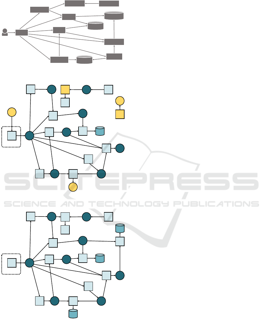
5.1 Robot Shop
Robot Shop (Instana, 2021) is a microservice-based
application simulating an e-commerce website selling
robots. It does not include failure handling mecha-
nisms like timeouts or circuit breakers, and its MSA
is documented to be as shown in Figure 8a.
We run both µMINER and µTOM on the pub-
licly available Kubernetes deployment of Robot Shop
to automatically generate a µTOSCA representation
of the MSA of Robot Shop. In both cases we ex-
ploited the Robot Shop’s load component to gener-
ate workload for the application and monitor the run-
time interactions among its components. In the case
of µMINER, we used the load directly in its dynamic
mining step (Muntoni et al., 2021). In the case of
µTOM, we instead deployed the application, used
the load component to generate workload, and then
downloaded the Kiali graph from the running deploy-
ment, which we then provided as input to µTOM
6
https://github.com/di-unipi-socc/microTOM/tree/
main/data/examples.
Offline Mining of Microservice-based Architectures
69
redis
payment
mongodb
mysql
rabbitmq
dispatch
users
catalogue
cart
web
ratings
shipping
(a)
edge
mB
mR
mysql
mysql.svc
ratings
ratings.svc
mR
shipping
shipping.svc
mR
catalogue
catalogue.svc
mR
mR
web
web.svc
mR
mongodb
mongodb.svc
mR
users
users.svc
mR
redis
redis.svc
mR
cart
carts.svc
mR
payment
payment.svc
rabbitmq.svc
rabbitmq
mR
dispatch
dispatch.svc
mR
load
d
d
d d
d
d
d
d
d
d
d
d
d
d
d
d
d
(b)
edge
mB
mR
mysql
mysql.svc
ratings
ratings.svc
mR
shipping
shipping.svc
mR
catalogue
catalogue.svc
mR
mR
web
web.svc
mR
mongodb
mongodb.svc
mR
users
users.svc
mR
redis
redis.svc
mR
cart
carts.svc
mR
payment
payment.svc
rabbitmq.svc
rabbitmq
mR
dispatch
dispatch.svc
mR
d
d
d d
d
d
d
d
d
d
d
d
d
d
d
d
d
d
(c)
Figure 8: MSAs of Robot Shop (a) taken from its documen-
tation and mined with (b) µMINER and (c) µTOM. Issues
in the MSA mined by µMINER are highlighted in yellow.
itself. The µTOSCA representations generated by
µMINER and µTOM are shown in Figure 8b and Fig-
ure 8c, respectively.
By looking at Figure 8, we can observe that both
µMINER and µTOM successfully identified all com-
ponents forming the MSA of Robot Shop. Given that
they are deployed as Kubernetes workloads managed
by Kubernetes services, each mined node is proxied
by a MessageRouter node implementing the corre-
sponding Kubernetes service. At the same time, we
can observe that there are some issues in the nodes
mined by µMINER, viz., (i) mongodb and mysql are
not recognised to be Databases, but rather typed as
Services, and (ii) the load component used to gener-
ated workload is included in the mined MSA, even
if it is not truly part of the MSA of Robot Shop.
The same does not hold for µTOM, which success-
fully identifies mongodb and mysql as Databases, and
which does not include the load component in the
mined MSA.
In addition, whilst both µMINER and µTOM ef-
fectively characterise the mined InteractsWith rela-
tionships, two relationships are missing in the MSA
mined by µMINER. The latter does not include the
interactions from payment and catalog to the Ku-
bernetes services managing rabbitmq and mongodb,
respectively. As a result, the portions including
rabbitmq and mongodb results to be disconnected
from the rest of the MSA in the µTOSCA topol-
ogy mined by µMINER. The same does not hold for
the µTOSCA topology mined by µTOM, which suc-
cessfully identifies all the interactions in the MSA of
Robot Shop.
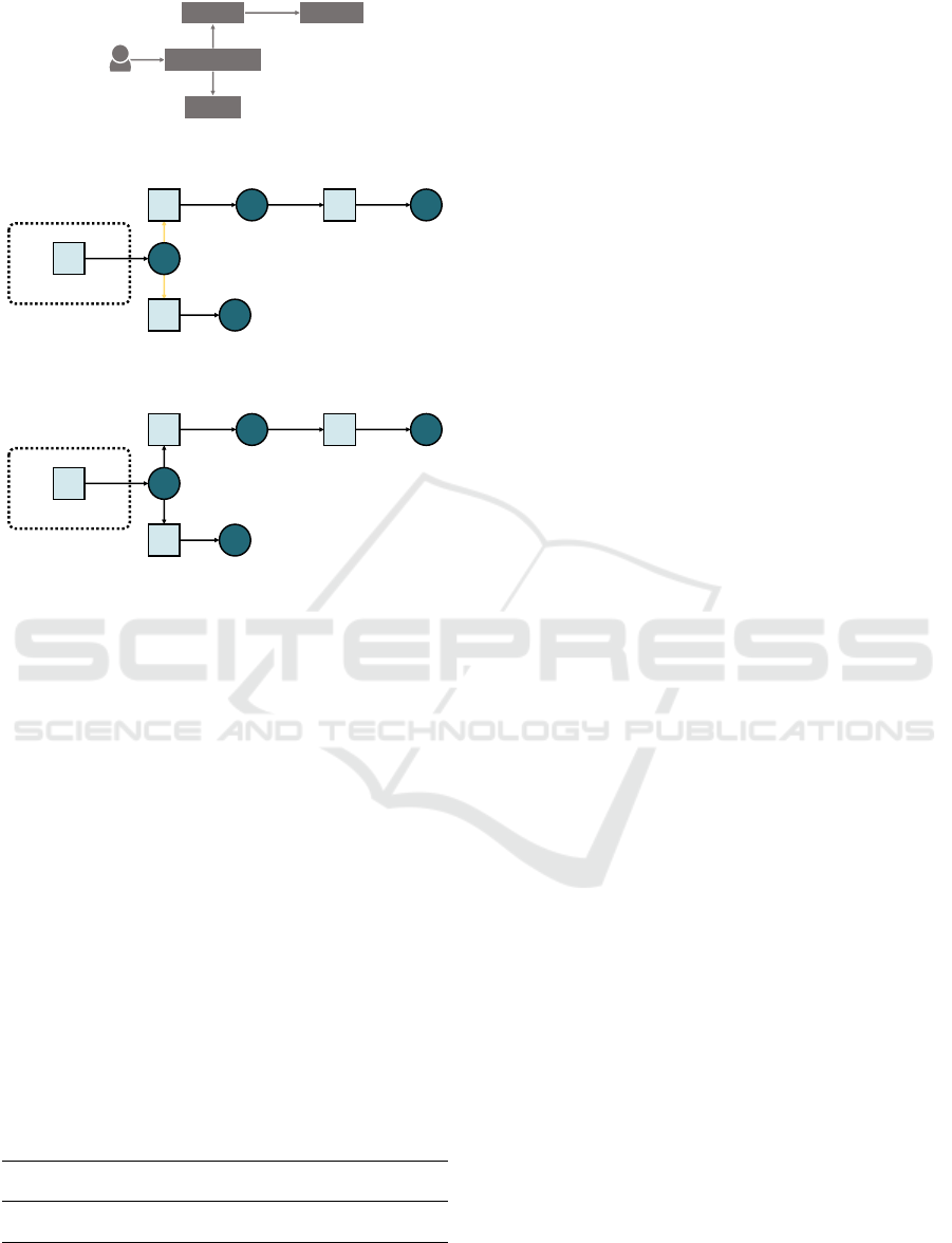
5.2 Book Info
Book Info (Istio, 2021) is a microservice-based ap-
plication developed to experiment Istio. It consists
of the four services in Figure 9a. We instrumented
its Kubernetes deployment by exploiting Istio to set
a timeout in the interactions between productpage
and details, and a circuit breaker in that between pro-
ductpage and reviews. This enabled us to show that
µTOM outperforms µMINER in determining whether
timeouts or circuit breakers are used in interactions.
The above can be readily observed by looking at
the µTOSCA representations of the MSA of Book
Info generated by µMINER and µTOM, which are
shown in Figure 9b and Figure 9c, respectively.
Whilst both µMINER and µTOM effectively mined all
components and interactions forming Book Info, only
µTOM successfully detected the timeout and circuit
breaker used in the InteractsWith relationships outgo-
ing from productpage.
CLOSER 2022 - 12th International Conference on Cloud Computing and Services Science
70
productpage
reviews
details
ratings
Istio timeout set
Istio circuit breaker set
(a)
d
d
edge
details
mR
productpage
reviewsreviews.svc
mR
ratingsratings.svc
productpage.svc
details.svc
d
mR
mR
(b)
edge
mR
details
mR
productpage
mR
reviewsreviews.svc
mR
ratingsratings.svc
productpage.svc
details.svc
d t
d
d c
(c)
Figure 9: MSAs of Book Info (a) taken from its documenta-
tion and mined with (b) µMINER and (c) µTOM. Issues in
the MSA mined by µMINER are highlighted in yellow.
5.3 Summary
Table 2 shows the success percentages of µMINER
and µTOM in identifying and typing nodes in our case
studies. The table also shows their success percent-
ages in identifying the interactions occurring among
such nodes, and in characterising such interactions
by eliciting whether dynamic discovery, timeouts, or
circuit breakers were used therein. In both cases,
the success percentages are counted as the ratio of
successfully identified/characterised nodes and inter-
actions over all those appearing in the applications
in our case studies. The numbers in Table 2 again
show how µTOM outperformed µMINER in mining
the MSAs of the two considered applications.
Table 2: Success percentages of µMINER and µTOM in
identifying and characterising the nodes and interactions in
the applications considered in our case studies.
nodes interactions
identified typed identified characterised
µMINER 100% 87.5% 97.3% 91.9%
µTOM 100% 100% 100% 100%
6 RELATED WORK
Several solutions have been proposed for mining the
MSAs of existing applications. The closest to ours
is µMINER (Muntoni et al., 2021), which is the only
existing solution mining a µTOSCA representation
of an application’s MSA from its Kubernetes deploy-
ment. As we already discussed in Section 1, µMINER
requires to run in a Kubernetes cluster with root priv-
ileges. This limits the applicability of µMINER, e.g.,
not allowing it to consider an existing deployment of
the application, like its production deployment. The
same does not hold for our technique, which can
work with existing Kubernetes application deploy-
ments, therein included their production deployment.
We also compared µMINER and our technique in their
mining capabilities, showing that our technique out-
performs µMINER in the quality of the µTOSCA rep-
resentation of mined MSAs (Section 5).
Other approaches worth mentioning are (Ma et al.,
2018), (Rademacher et al., 2020), (Alshuqayran et al.,
2018), (Granchelli et al., 2017b), and (Granchelli
et al., 2017a). They introduce different techniques,
which differ from ours in the mining approach and in
the generated representation of mined MSAs. As for
the latter, we generate a representation of the mined
MSA where components are distinguished among ser-
vices, integration components, and databases. This
is intended to enable checking whether the mined
MSA is affected by some architectural smells, by
giving the mined MSA to smell detection tools like
µFRESHENER (Brogi et al., 2020). The same is not
supported by (Ma et al., 2018), (Rademacher et al.,
2020), (Alshuqayran et al., 2018), (Granchelli et al.,
2017b), and (Granchelli et al., 2017a), which do not
distinguish the type of mined components.
As for the enacted mining approach, (Ma et al.,
2018), (Rademacher et al., 2020), and (Alshuqayran
et al., 2018) reconstruct the MSA of an application
by statically analysing the source code of its compo-
nents. They hence follow a “white-box” approach, as-
suming the availability of the source code of the com-
ponents forming a MSA. Our mining technique in-
stead works also in “black-box” scenarios, viz., when
the source code of application components is not
available. We indeed only require the manifest files
specifying its deployment in Kubernetes and the run-
time interactions monitored among its components.
In addition, while our mining solution can be fully
automated, both (Rademacher et al., 2020) and (Al-
shuqayran et al., 2018) require developers to manu-
ally intervene while mining a MSA.
Similar considerations apply to (Granchelli et al.,
2017a) and (Granchelli et al., 2017b), which also em-
Offline Mining of Microservice-based Architectures
71

ploy a white-box, semi-automated technique to mine
a MSA from the source code of its components. Such
technique is semi-automated since it relies on devel-
opers to manually refine the obtained MSA by remov-
ing the infrastructure facilities (e.g., service discov-
ery components) used to let application components
interoperate. At the same time, (Granchelli et al.,
2017a) and (Granchelli et al., 2017b) are a step closer
to ours, given that they enrich the mined MSA by rely-
ing on runtime monitored interactions. Our technique
hence differs from what proposed in (Granchelli et al.,
2017a) and (Granchelli et al., 2017b), since it can
fully automate the mining of a MSA, and since it
can work in black-box scenarios, i.e., when the source
code of some application components is not available.
Finally, it is worth relating our mining technique
with existing system for monitoring Kubernetes-
based application deployments. For instance, Kiali
(Section 2.3), KubeView (Coleman, 2021), and
WeaveScope (Weaveworks, 2021) are three open
source tools for monitoring and visualising the struc-
ture of applications deployed with Kubernetes. They
differ from our technique mainly because of their ulti-
mate goal, which is to enable visualising the deployed
Kubernetes objects (e.g., workloads and services) and
their interactions. Our solution instead generates a
machine-readable representation of a MSA, whose
components are distinguished among services, inte-
gration components, and databases forming a MSA,
and where component interactions are characterised
by indicating whether client-side service discovery,
timeouts, or circuit breakers are used therein.
Similar considerations apply to Instana (Instana,
2021), another tool for visualising applications de-
ployed with Kubernetes. Instana (Instana, 2021) is
however closer to our mining technique in the gen-
erated representation, given that it distinguishes the
deployed component among services and databases.
Our mining technique goes beyond this, by recog-
nising whether deployed components are imple-
menting message routing/brokering patterns, and
whether service discovery, timeouts, or circuit break-
ers are used in component interactions. Additionally,
whilst Instana (Instana, 2021) is a commercial and
subscription-based tool, an open source implementa-
tion of our technique is publicly available on GitHub.
7 CONCLUSIONS
We presented a technique for mining MSAs from
their Kubernetes deployment. Our technique also in-
puts the component interactions monitored in a for-
mer deployment with Kiali, and it process all such
μMiner
μFreshener
μTOSCA
Kiali graph
JSON
μTOM
Kubernetes
manifest files
YAML
"smell-free"
μTOSCA
YAML
YAML
Figure 10: Updated µTOSCA toolchain. Existing tools are
in light blue, whilst the newly introduced tool is darker.
inputs offline. As a result, it automatically generates
a representation of the mined MSA in µTOSCA, a
microservice-oriented profile of the TOSCA standard.
We have also presented µTOM, a prototype im-
plementation of our mining technique. µTOM plugs
into the µTOSCA toolchain (Soldani et al., 2021),
as shown in Figure 10. It actually provides an of-
fline alternative to µMINER (Muntoni et al., 2021) to
generate µTOSCA representations of MSAs, which
can still be processed by µFRESHENER (Neri et al.,
2020) to identify and resolve the architectural smells
therein. µTOM showed to outperform µMINER in
generating more informative representations of mined
MSAs, without requiring to run the target applica-
tion in a suitably configured testing environment, but
rather by processing the information monitored with
Kubernetes-native monitoring in former application
deployments, e.g., production deployments. If such
information is not available, e.g., since Kubernetes-
native monitoring is not enabled, one could anyhow
still use µMINER to mine the MSA of an application.
We anyhow plan to further enhance the mining ca-
pabilities of µTOM and, more generally, of our min-
ing technique. For instance, we plan to enhance the
detection of the type of mined components, which
currently detects message brokers or databases when
they run from official Docker images of software dis-
tributions known to implement such components. The
type of component run by a Docker image may be
detected by exploiting machine learning techniques,
e.g., similary to what done in (Guidotti et al., 2019)
to predict the popularity of Docker images, or by in-
specting them with approaches like that proposed in
DockerFinder (Brogi et al., 2017).
We also plan to enable our technique to work with
other technologies than Kubernetes, Istio, and Kiali.
For instance, we plan to include support for mani-
fest files specifying the deployment of a microservice-
based application with Docker Compose/Swarm. We
also plan to support processing the interactions mon-
itored with other tracing tools, e.g., Jaeger (Jaeger,
2021) or Zipkin (OpenZipkin, 2021).
CLOSER 2022 - 12th International Conference on Cloud Computing and Services Science
72

REFERENCES
Alshuqayran, N., Ali, N., and Evans, R. (2018). To-
wards micro service architecture recovery: An em-
pirical study. In Gorton, I., Buhnova, B., Ernst, N.,
and Szyperski, C., editors, 2018 IEEE International
Conference on Software Architecture, pages 47–4709.
IEEE. https://doi.org/10.1109/ICSA.2018.00014.
Brogi, A., Neri, D., and Soldani, J. (2017). Dockerfinder:
Multi-attribute search of docker images. In 2017
IEEE International Conference on Cloud Engineering
(IC2E), pages 273–278. https://doi.org/10.1109/IC2E.
2017.41.
Brogi, A., Neri, D., and Soldani, J. (2020). Freshen-
ing the air in microservices: Resolving architectural
smells via refactoring. In Yangui, S., Bouguettaya,
A., Xue, X., Faci, N., Gaaloul, W., Yu, Q., Zhou,
Z., Hernandez, N., and Nakagawa, E. Y., editors,
Service-Oriented Computing – ICSOC 2019 Work-
shops, pages 17–29, Cham. Springer. https://doi.org/
10.1007/978-3-030-45989-5 2.
Coleman, B. (2021). KubeView. https://github.com/
benc-uk/kubeview.
Forti, S., Bisicchia, G., and Brogi, A. (2022). Declar-
ative continuous reasoning in the cloud-IoT contin-
uum. Journal of Logic and Computation. https:
//doi.org/10.1093/logcom/exab083.
Google Cloud (2021). Online Boutique. https://github.com/
GoogleCloudPlatform/microservices-demo.
Granchelli, G., Cardarelli, M., Di Francesco, P., Malavolta,
I., Iovino, L., and Di Salle, A. (2017a). MicroART:
A software architecture recovery tool for maintain-
ing microservice-based systems. In Malavolta, I. and
Capilla, R., editors, 2017 IEEE International Confer-
ence on Software Architecture Workshops, pages 298–
302. IEEE. https://doi.org/10.1109/ICSAW.2017.9.
Granchelli, G., Cardarelli, M., Di Francesco, P., Malavolta,
I., Iovino, L., and Di Salle, A. (2017b). Towards
recovering the software architecture of microservice-
based systems. In Malavolta, I. and Capilla, R., edi-
tors, 2017 IEEE International Conference on Software
Architecture Workshops, pages 46–53. IEEE. https:
//doi.org/10.1109/ICSAW.2017.48.
Guidotti, R., Soldani, J., Neri, D., Brogi, A., and Pe-
dreschi, D. (2019). Helping your Docker images
to spread based on explainable models. In Brefeld,
U., Curry, E., Daly, E., MacNamee, B., Marascu,
A., Pinelli, F., Berlingerio, M., and Hurley, N., edi-
tors, Machine Learning and Knowledge Discovery in
Databases, pages 205–221, Cham. Springer. https:
//doi.org/10.1007/978-3-030-10997-4
13.
Hohpe, G. and Woolf, B. (2003). Enterprise Integration
Patterns: Designing, Building, and Deploying Mes-
saging Solutions. Addison-Wesley, 1st edition.
Instana (2021). Instana. https://www.instana.com.
Instana (2021). Robot Shop. https://github.com/instana/
robot-shop.
Istio (2021). Book Info. https://github.com/istio/istio/tree/
master/samples/bookinfo.
Jaeger (2021). Jaeger. https://www.jaegertracing.io.
Kratzke, N. and Quint, P.-C. (2017). Understanding cloud-
native applications after 10 years of cloud comput-
ing - a systematic mapping study. Journal of Systems
and Software, 126:1–16. https://doi.org/10.1016/j.jss.
2017.01.001.
Ma, S., Fan, C., Chuang, Y., Lee, W., Lee, S., and Hsueh,
N. (2018). Using service dependency graph to ana-
lyze and test microservices. In Reisman, S., Ahamed,
S. I., Demartini, C., Conte, T. M., Liu, L., Clay-
comb, W. R., Nakamura, M., Tovar, E., Cimato, S.,
Lung, C.-H., Takakura, H., Yang, J.-J., Akiyama, T.,
Zhang, Z., and Hasan, K., editors, 2018 IEEE 42nd
Annual Computer Software and Applications Confer-
ence, pages 81–86. IEEE. https://doi.org/10.1109/
COMPSAC.2018.10207.
Muntoni, G., Soldani, J., and Brogi, A. (2021). Min-
ing the architecture of microservice-based applica-
tions from their kubernetes deployment. In Zirpins,
C., Paraskakis, I., Andrikopoulos, V., Kratzke, N.,
Pahl, C., El Ioini, N., Andreou, A. S., Feuerlicht,
G., Lamersdorf, W., Ortiz, G., Van den Heuvel, W.-
J., Soldani, J., Villari, M., Casale, G., and Plebani,
P., editors, Advances in Service-Oriented and Cloud
Computing, pages 103–115, Cham. Springer. https:
//doi.org/10.1007/978-3-030-71906-7 9.
Neri, D., Soldani, J., Zimmermann, O., and Brogi,
A. (2020). Design principles, architec-
tural smells and refactorings for microser-
vices: a multivocal review. SICS Software-
Intensive Cyber-Physical Systems, 35(1):3–15.
https://doi.org/10.1007/s00450-019-00407-8.
OASIS (2020). TOSCA simple profile in
YAML. v1.3, https://docs.oasis-open.org/
tosca/TOSCA-Simple-Profile-YAML/v1.3/
TOSCA-Simple-Profile-YAML-v1.3.pdf.
OpenZipkin (2021). Zipkin. https://zipkin.io.
Rademacher, F., Sachweh, S., and Z
¨
undorf, A. (2020).
A modeling method for systematic architecture re-
construction of microservice-based software systems.
In Nurcan, S., Reinhartz-Berger, I., Soffer, P.,
and Zdravkovic, J., editors, Enterprise, Business-
Process and Information Systems Modeling, pages
311–326, Cham. Springer. https://doi.org/10.1007/
978-3-030-49418-6
21.
Soldani, J., Muntoni, G., Neri, D., and Brogi, A. (2021).
The µTOSCA toolchain: Mining, analyzing, and
refactoring microservice-based architectures. Soft-
ware: Practice and Experience, 51(7):1591–1621.
https://doi.org/10.1002/spe.2974.
Soldani, J., Tamburri, D. A., and Van Den Heuvel, W.-J.
(2018). The pains and gains of microservices: A sys-
tematic grey literature review. Journal of Systems and
Software, 146:215–232. https://doi.org/10.1016/j.jss.
2018.09.082.
Weaveworks (2021). WeaveScope. https://www.weave.
works/oss/scope.
Zimmermann, O. (2017). Microservices tenets.
Computer Science: Research and Develop-
ment, 32(3–4):301–310. https://doi.org/10.1007/
s00450-016-0337-0.
Offline Mining of Microservice-based Architectures
73
