
ManLang: A Requirements Modeling Language for the Production
Planning in Manufacturing
Mert Ozkaya
1
and Gulsah Gokhan Gokcek
2
1
Yeditepe University, Department of Computer Engineering, Istanbul, Turkey
2
Eryaz Software, Istanbul, Turkey
Keywords:
Production Planning, Model-based Engineering, Modeling Language, Multiple-viewpoints Modeling.
Abstract:
In manufacturing industries, production planning involves making early decisions about the design and pro-
duction of a product that focuses on different concerns such as the investment to be made, the product (and
its parts) to be manufactured, production line, workstations, and production processes. The decisions and
requirements about those concerns tend to be specified using office tools in many manufacturing companies
(e.g., MS Excel). However, office tools lead to some issues including (i)the lack of support for separation
of concerns, graphical editing, precise notation set, and error detection, and (ii)inconsistent and incomplete
requirements specifications. In this paper, we propose a modeling language called ManLang for specifying the
production planning requirements graphically using multiple viewpoints (i.e., investment, product, line, work-
station, and process). With ManLang, the different viewpoint models may be specified separately in a way
that the viewpoint models can also be traced via the defined relationships between the viewpoints. We support
ManLang with a graphical modeling editor, which enables for the multiple-viewpoints modeling and the auto-
mated model validation against such properties as model completeness and correctness. We further evaluated
the usability of ManLang and its editor via a survey conducted among the practitioners from manufacturing
industries.
1 INTRODUCTION
Manufacturing industries aim to produce the high
quality products in the least amount of time possi-
ble. With the advent of industry 4.0, digitalising the
manufacturing engineering (Freddi, 2018; Kroll et al.,
2018; Chryssolouris et al., 2009) has gained ever-
increasing importance to maximise the business pro-
ductivity, and therefore, the recent technologies and
innovations on the systems and software engineering
play key roles in making manufacturing more produc-
tive and effective. Indeed, many computer-aided soft-
ware tools have been developed (e.g., the tools for the
process simulations and computer aided manufactur-
ing (CAM), robotic and automation simulation soft-
ware, etc.), which support the product manufactur-
ing from different perspectives including the design of
production systems and processes, robot behaviours,
their simulations and implementation.
In this paper, we focus on the production plan-
ning of manufacturing engineering, which is one of
the most important aspects of manufacturing and need
to be handled carefully to achieve the optimal in-
vestment for a product while maximising the product
quality and reducing the cost and effort needed. To
this end, we analysed the manufacturing domain to-
gether with the domain experts who work for some
of the biggest car and truck manufacturers in Eu-
rope (e.g., TOFAS, Ford Otosan, and Volvo), which
are the partners of the AITOC ITEA project
1
that
our research here is motivated from. As we ob-
served via series of interviews, to specify the require-
ments for production planning, practitioners need to
consider different concerns at different level of de-
tails where many different but related data need to be
recorded and manipulated and diverse decisions need
to be made using those data for optimal production
planning. The concerns about production planning
may include the variants about the investment to be
made (e.g., capacity, annual production, robotic/man-
ual time, etc.), the parts and other details of the prod-
uct to be manufactured, the production line configu-
rations, the workstation configurations for each line,
the production processes to be performed in each sta-
tion and their configuration, and the resources that
1
AITOC: https://itea4.org/project/aitoc.html
Ozkaya, M. and Gokcek, G.
ManLang: A Requirements Modeling Language for the Production Planning in Manufacturing.
DOI: 10.5220/0011058400003176
In Proceedings of the 17th International Conference on Evaluation of Novel Approaches to Software Engineering (ENASE 2022), pages 395-404
ISBN: 978-989-758-568-5; ISSN: 2184-4895
Copyright
c
2022 by SCITEPRESS – Science and Technology Publications, Lda. All rights reserved
395

need to be used in each process. However, our in-
terviews with the manufacturing practitioners reveals
that production planning is not performed in an ef-
fective and precise way in manufacturing industries.
While the product requirements and related models
are typically specified in a standardized and better or-
ganized way (both in paper format and/or digital for-
mat), those specifications are mainly to do with defin-
ing the product functionalities in its final state. Infor-
mation related to how the product should be manufac-
tured is often missing or not sufficient for process and
production planning. The production system require-
ments that will guide and restrict the choice of pro-
duction lines and their stations, the production pro-
cesses involved in each line along with the resources
to be used are often in different paper formats and are
complex to understand and use.
In our AITOC ITEA project, we conducted a sur-
vey among 16 manufacturing practitioners to under-
stand practitioners’ experiences with the current tools
they use for specifying the production planning re-
quirements. So, we observed that practitioners tend
to use the office tools (mostly MS Excel) for specify-
ing the product and production system requirements.
One may use Excel to specify the requirements data in
the form of rows and columns and execute formulas
to perform calculations or Powerpoint to draw some
boxes and lines. However, such form of specifications
are not so helpful. It is not possible with the office
tools to specify the requirements about different con-
cerns (e.g., investment, product, line, station, and pro-
cess) in a way that is easy to understand, communi-
cate, and trace. Indeed, the requirements for different
concerns cannot be separated and specified precisely.
Also, one may not use office tools to analyse the re-
quirements specifications for such analysis goals as
completeness (i.e., the specification includes all nec-
essary details), consistency (i.e., the requirements are
consistent with each other), and correctness (i.e., the
requirements are syntactically and semantically cor-
rect).
To address the problems discussed above, we con-
sider a model-based solution (Seidewitz, 2003; Whit-
tle et al., 2014), which provides such benefits as the
separation of concerns, abstraction, graphical model-
ing, precise specifications, and tool support for mod-
eling editing and the automated model checking. So,
in this paper, we propose a new requirements mod-
eling language called ManLang and its supporting
modeling editor. ManLang supports the multiple-
viewpoints modeling and enables the production plan-
ning requirements to be separated into different view-
point models that each tackle with a particular con-
cern. The supported viewpoints are to do with (i)the
investment needed for a product, (ii)the product to
be manufactured, (iii)the production line in which the
product is manufactured, (iv)the stations employed in
the production lines, and (v)the production processes
operated on each line station. ManLang is essentially
intended for the specifications of requirements for di-
verse manufacturing domains and therefore enables
the viewpoint models (and their elements) to vary
depending on the domain needs. Indeed, one may
specify parameters for the viewpoint models and their
modeling elements to make them hold specific types
of information defined by the users for the particu-
lar domain needs. ManLang defines the relationship
between the modeling viewpoints and those relation-
ships are ensured via the modeling editor for the trace-
ability between the viewpoint models. Moreover, the
modeling editor further checks for the completeness
and correctness of the viewpoint models, where the
former is concerned with if the viewpoint models in-
clude all the elements that are defined by the language
and the latter is concerned with if the viewpoint mod-
els satisfy the language definition rules (e.g., the mul-
tiplicities and relationships).
In the rest of this paper, we firstly discuss the
related work about the general-purpose and domain-
specific languages that can be used for the production
planning requirements. Later, we introduce the Man-
Lang language in terms of the definitions of the view-
points. Next, we introduce the editor tool support for
ManLang. Lastly, we discuss the preliminary evalu-
ation of the ManLang and its editor tool via a survey
conducted among among a set of practitioners.
2 RELATED WORK
The literature includes several modeling approaches
that could be used for the modeling of production
planning requirements. As aforementioned, while
office tools are highly popular, they do not aid in
the precise specifications of requirements that can be
interpreted in the same way by different stakehold-
ers and processed for analysis purposes. One may
alternatively use well-known, general-purpose mod-
eling languages such as SysML (Friedenthal et al.,
2008), UML (Rumbaugh et al., 2004), and BPMN
(V
¨
olzer, 2010). These languages have precise graph-
ical notation sets that could be used for the multiple-
viewpoints modeling. Note however that those mod-
eling languages have general-purpose scope and do
not offer notation set specific to the manufacturing do-
main. UML may be extended for the production plan-
ning domain with their profiling mechanism. How-
ever, with the profiling mechanism, one may not vio-
ENASE 2022 - 17th International Conference on Evaluation of Novel Approaches to Software Engineering
396
late the existing syntax and semantics rules for UML
and remove any elements. The new language must
also be a valid UML model. So, whenever the UML
language specification is updated, the extended lan-
guage needs to be modified too. Also, the extended
language may only be used with the modeling tool
through which the profiling mechanism is used.
The literature also includes domain-specific mod-
eling languages (DSMLs) for the specifications of
manufacturing requirements, e.g., (Vjestica et al.,
2020; Weissenberger et al., 2015; Petrasch and
Hentschke, 2016; L
¨
utjen and Rippel, 2015; Witsch
and Vogel-Heuser, 2012; Jiwei et al., 2008). Those
languages offer graphical and domain-specific nota-
tion sets for specifying manufacturing requirements.
However, the main point of interest herein is cen-
tered around the production process flow modeling
rather than multiple-viewpoints modeling that encom-
passes a set of inter-related concerns about produc-
tion planning including the investment, product, and
production line and workstations concerns as is the
case with our approach. Vje
ˇ
stica et al. (Vjestica
et al., 2020) proposed a modeling language for spec-
ifying the production processes at two levels of ab-
stractions. That is, first the high-level process flow
is specified, which is then detailed with execution-
specific details for such tools as simulators and digital
twin tools. Weißenberger et al. (Weissenberger et al.,
2015; Witsch and Vogel-Heuser, 2012) proposed a
modeling language that supports the specifications of
manufacturing requirements in terms of three view-
points: technical system, production process, and
MES model. The technical system viewpoint is con-
cerned with the technological structure of the plant
in which the product is manufactured. The produc-
tion process model is concerned with the process flow
specification in terms of activities and their transi-
tions. The MES model is concerned with the function
definitions in terms of input parameters and output re-
sults. Petrasch et al. (Petrasch and Hentschke, 2016)
proposed a modeling language based on BPMN that
enables to specify graphical production process mod-
els with the considerations of different Industry 4.0
aspects. That is, one may specify the process models
using such concepts as Cloud App, IoT devices, de-
vice data, actuation and sensing tasks, HCI, and mo-
bility which play key roles for the Industry 4.0 appli-
cations. L
¨
utjen et al. (L
¨
utjen and Rippel, 2015) pro-
posed a modeling approach called GRAMOSA that
promotes the modeling of production processes with
the consideration of material and control flows. Jiwei
et al. (Jiwei et al., 2008) proposed a formal model-
ing approach for the production process flows which
is based on the petri nets (Brauer et al., 1987) that en-
ables to specify formally analysable dynamic models
graphically.
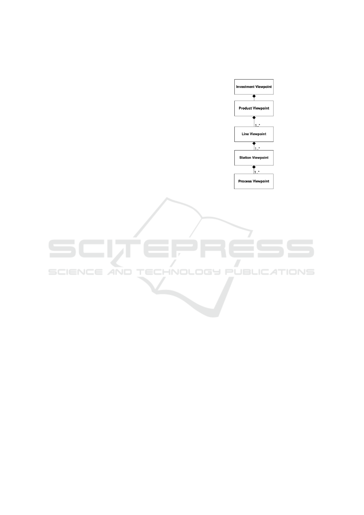
Figure 1: ManLang’s viewpoint architecture.
3 ManLang OVERVIEW
ManLang supports multiple modeling viewpoints.
These are the investment, product, line, station and
process viewpoints. Each viewpoint deals with a dif-
ferent concern of production planning and is sup-
ported with a distinct notation set for the specifica-
tions of solution models in that viewpoint. In the rest
of this section, the viewpoint definitions (i.e., meta-
model) are discussed where the viewpoint concepts
and their relations are depicted using UML’s class di-
agram notation.
Figure 1 shows that viewpoints are related to each
other via the composition (i.e., part-whole) relation-
ship. That is, if a viewpoint is composed of another
viewpoint, a model of the latter viewpoint may be ac-
cessible via the model of the former viewpoint. In-
deed, an investment viewpoint model enables a model
of the product viewpoint to be accessible. Also,
the viewpoints relate to each other with multiplici-
ties (e.g., 1..*), which constrain the number of the
viewpoint models that can be accessible from another
viewpoint model. Any product viewpoint model may
for instance enable one or more line viewpoint models
to be accessible.
Each viewpoint is defined in terms of its meta-
model that consists of the concepts, attributes, and
their relationships of that viewpoint. A viewpoint
concept represents a modeling element for that view-
point. Any concept may include some attributes that
define the data structure of the associated modeling
element. Also, a concept may represent another view-
ManLang: A Requirements Modeling Language for the Production Planning in Manufacturing
397
point. That is, the modeling element for such a con-
cept is essentially a reference to a model of another
viewpoint. Concepts may relate to each other via the
composition relationship. That is, any modeling ele-
ment may include some other modeling elements.
Besides the meta-model definitions, each view-
point is associated with a concrete symbol list that
consists of a graphical symbol for each concept of that
viewpoint. Likewise, the concept attributes and rela-
tionships are also associated with graphical symbols.
So, users may use the symbols under certain rules so
as to specify the viewpoint models.
The abstract concepts and concrete symbols for
each viewpoint have been determined via a series
of interviews conducted with the manufacturers con-
tributing to our project
1
and inspired from the previ-
ous work conducted in another ITEA project called
ENTOC
2
which established the basis for our project.
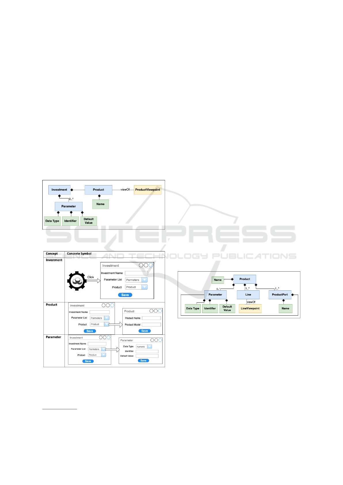
Figure 2: The meta-model definition for the investment
viewpoint.
Figure 3: The concrete symbols for the investment view-
point.
2
https://itea4.org/project/entoc.html
3.1 Investment Viewpoint
The investment viewpoint is concerned with the in-
vestment to be made for any product manufacturing.
Figure 2 shows the meta-model definition of the
investment viewpoint, which consists of three con-
cepts – investment, product and parameter. The in-
vestment here is the main concept, which is defined
in terms of the product and parameter concepts. An
investment element derived from the investment con-
cept may consist of zero or more parameters that
may be used to specify any data to be used concern-
ing the calculations for a product investment such as
the capacity, annual production, working days/hours,
robotic/manual time, and engineering cost. A param-
eter is specified with the data type, data identifier, and
value attributes. The investment element may include
exactly one product derived from the product concept,
which represents the requirements of the product to be
invested and is specified with the product name and
model instantiated from the product viewpoint.
Figure 3 shows the concrete symbols that cor-
respond to the concepts defined in the meta-model
given in Figure 2. The investment concept is mapped
to a graphical symbol, and whenever the symbol is
clicked, a new dialog box opens for specifying the
investment name, product details, and parameters.
Clicking product opens up another dialog box for
specifying the product name and the model element
which is clicked to open up a new sub-editor for spec-
ifying the product viewpoint model as discussed in
the next sub-section.
Figure 4: The meta-model definition for the product view-
point.
3.2 Product Viewpoint
The product viewpoint is concerned with any infor-
mation required for the product to be manufactured.
Figure 4 shows the meta-model definition of the
product viewpoint, which consists of four concepts
– product, product part, parameter and line. The
product herein is the main concept that represents the
product modeling element to be specified. A product
element derived from the product concept may consist
of the name attribute and the elements derived from
ENASE 2022 - 17th International Conference on Evaluation of Novel Approaches to Software Engineering
398
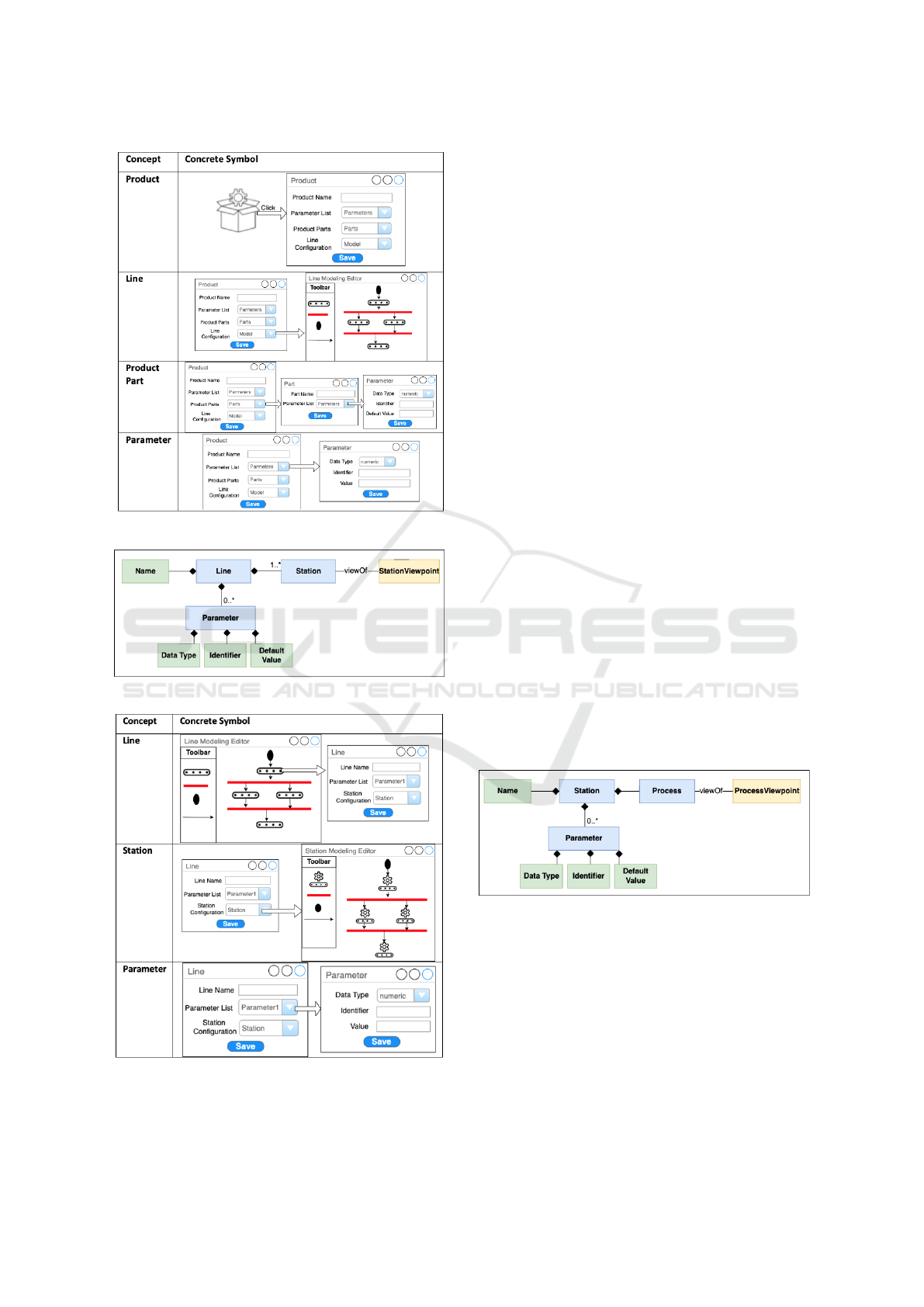
Figure 5: The concrete symbols for the product viewpoint.
Figure 6: The meta-model definition for the line viewpoint.
Figure 7: The concrete symbols for the line viewpoint.
the rest of the concepts (i.e., product part, parameter,
and line). A product may have zero or more param-
eters, representing any data about the product to be
manufactured and specified in terms of the data type,
identifier, and value attributes. A product may have
one or more line elements where the product parts are
processed to produce the end product. The produc-
tion of any product may be divided into multiple lines
each of which is responsible for a particular set of op-
erations to be performed on the product parts. Multi-
ple production lines may be located sequentially pro-
viding input (such as product parts, information, and
energy) to each other or in parallel (representing the
parallel operations to be performed on different parts).
Each line element here is modeled separately as a line
viewpoint model. Lastly, a product may be composed
of one or more product part elements, each represent-
ing a distinct part of the product that could be pro-
cessed over the line stations and specified in terms of
the name attribute and a set of parameters.
Figure 5 shows the concrete symbols for the prod-
uct viewpoint whose meta-model is given in Figure 4.
So, whenever the product model element is clicked in
the investment viewpoint model, a new editor opens
for specifying the product element with the graphi-
cal symbol shown here. Upon clicking the product
symbol, a new dialog box opens up for specifying
the product details (i.e., parameters, line and prod-
uct parts). Upon clicking the line configuration on
the dialog box, a sub-editor opens for drawing a line
configuration model in terms of the line elements and
their sequential/concurrent flows. The red line on the
editor is employed for indicating the lines that operate
concurrently while the black directed arrow indicating
the lines operating sequentially.
Figure 8: The meta-model definition for the station view-
point.
3.3 Line Viewpoint
The line viewpoint is concerned with the require-
ments for a production line where the product parts
are processed together with other inputs (e.g., infor-
mation and energy) via the technical resources.
Figure 6 shows the meta-model definition of the
line viewpoint. So, the line element derived from the
line concept definition consists of the name attribute
ManLang: A Requirements Modeling Language for the Production Planning in Manufacturing
399
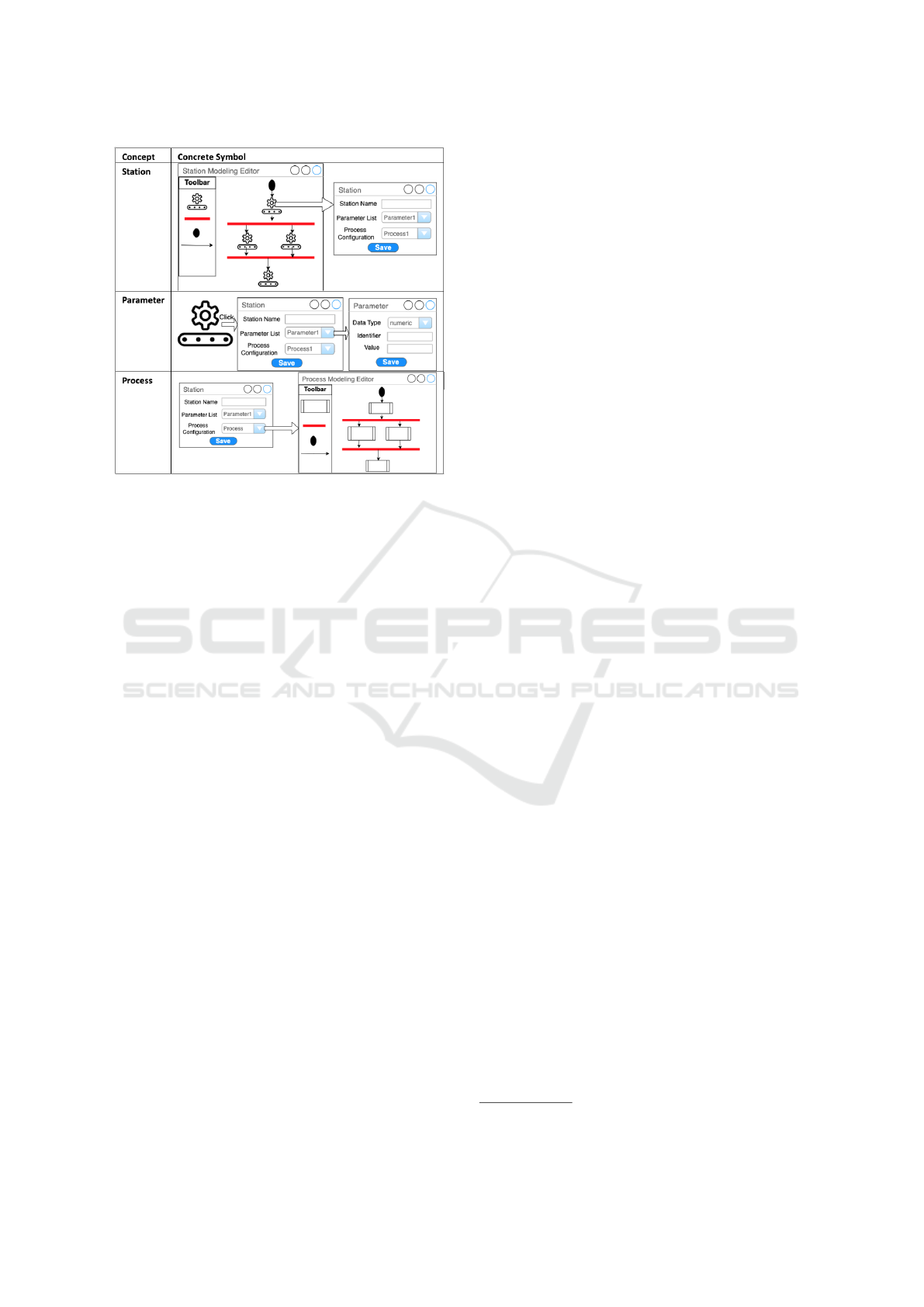
Figure 9: The concrete symbols for the station viewpoint.
and the elements derived from the parameter and sta-
tion concepts. A line element may be composed of
zero or more parameters, representing the data de-
scribing the production line (e.g., automation rate of
the line). A parameter is specified with the type of
data, the parameter identifier and the data value. A
line element may also include one or more station el-
ements each of which represents a workstation where
a particular set of operation(s) are performed on the
product parts. The line stations may be designed to be
operated in parallel or sequentially. A station element
is modeled separately as a station viewpoint model
discussed in the next sub-section.
Figure 7 shows the concrete symbols for the line
viewpoint that correspond to the concepts defined in
the meta-model given in Figure 6 . So, whenever a
line symbol specified in the line configuration model
of the product viewpoint is clicked, a new dialog box
opens for specifying the line name, parameter list and
a station configuration model. Whenever, the station
configuration model is clicked on the dialog box, a
new sub-editor opens for specifying a station config-
uration in terms of the stations and their sequential/-
concurrent flows. Note that the red line on the editor is
employed for indicating the stations that operate con-
currently while the black directed arrow indicating the
stations operating sequentially.
3.4 Station Viewpoint
The station viewpoint is concerned with the require-
ments about the workstations employed in a produc-
tion line where the product parts pass through some
processes that are relevant to that line.
Figure 8 shows the meta-model definition of the
station viewpoint, which consists of three concepts –
station, parameter, and process. Any station derived
from the station concept is composed of the name at-
tribute and the elements derived from the process and
parameter concepts. Each station element is specified
with zero or more parameters for specifying the data
about the station. A station element includes one or
more processes that perform operations on the prod-
uct parts with the use of technical resources. Multi-
ple processes for a station may be performed sequen-
tially or in parallel, where the former promotes the
processes to provide input to each other (e.g., product
parts) and the latter promotes the processes to work
on different product parts concurrently.
Figure 9 shows the concrete symbols for the sta-
tion viewpoint whose meta-model definition is given
in Figure 8. Whenever the station symbol is clicked
on a station configuration model, a new dialog box
opens for specifying the station element in terms of
the name of the station, parameters, and the process
model. Whenever the process configuration model
is clicked, a new sub-editor opens for specifying the
configurations of processes involved in the current
station in terms of the processes and their sequential/-
concurrent flows. Note that the red line on the editor
is employed for indicating the processes that operate
concurrently while the black directed arrow indicat-
ing the processes operating sequentially.
3.5 Process Viewpoint
The process viewpoint is concerned with making de-
cisions about the production processes to be per-
formed in the line workstations. To define a process,
we use the VDI 3682 standard
3
, which offers a for-
malised process description. That is, each process is a
set of interacting actions in a system that transforms,
transports or stores product, energy or information.
Any process may accept some input (i.e., product, en-
ergy or information) and be performed by a technical
resource to produce some output (i.e., product, energy
or information). A process is essentially realised by a
resource that includes software which run on an em-
bedded device so as to execute the process behaviour.
Figure 10 shows the meta-model definition of the
process viewpoint. So, the process viewpoint includes
a process concept defined in terms of the input, op-
eration, output, parameter and relationship concepts.
That is, a process element is specified with the ele-
ments derived from those concepts. Each process is
composed of at least one input, one output, and one
relationship. An input/output concept may include an
3
VDI: https://www.vdi.de/en/home/vdi-standards
ENASE 2022 - 17th International Conference on Evaluation of Novel Approaches to Software Engineering
400
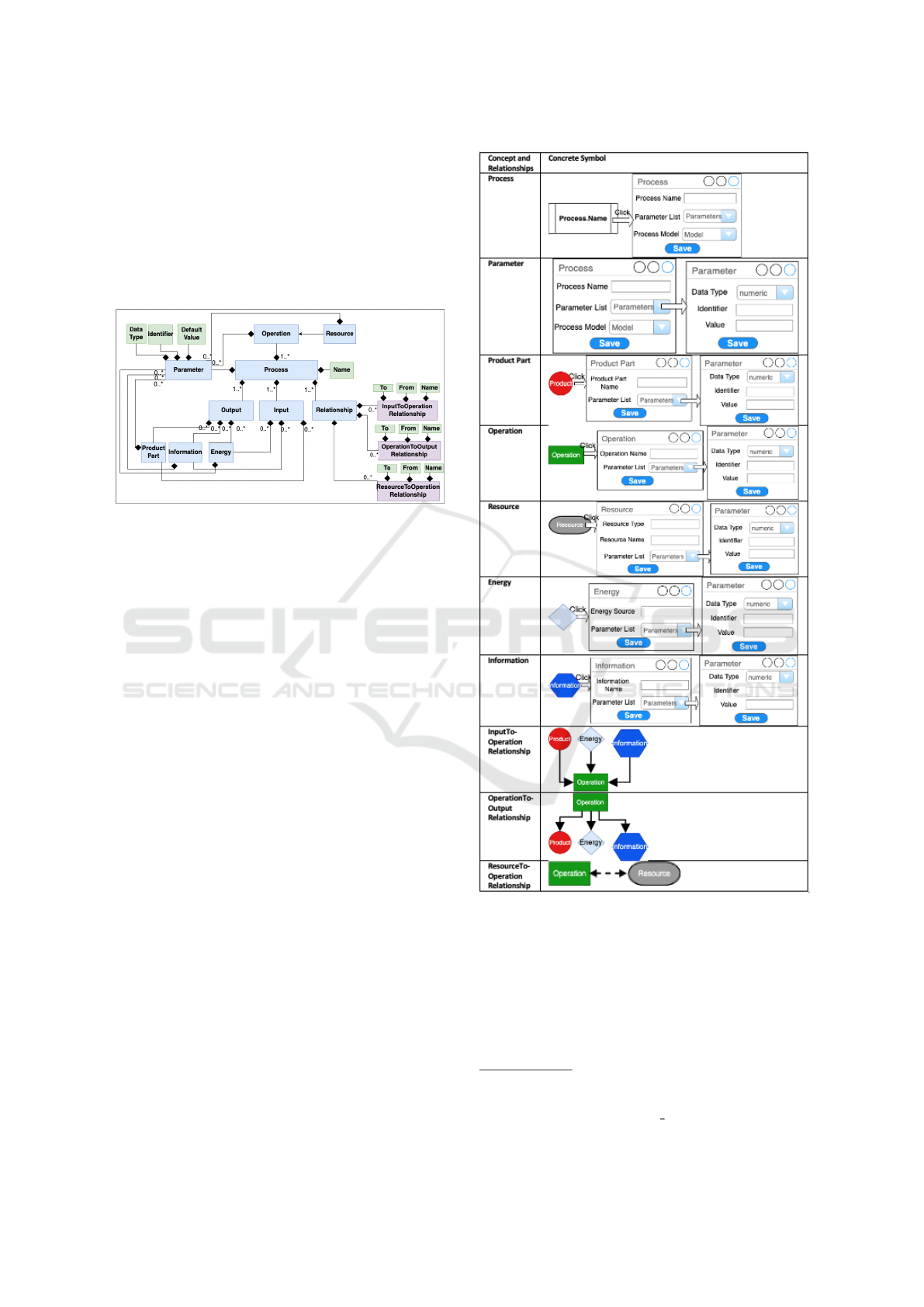
element which derives from either one of the product
part, information, or energy concepts. Each process
is composed of one or more operations (e.g., shaping,
forming, cutting, joining, and coating). An operation
is specified with the name of the operation to be per-
formed and any data parameters about the operation.
An operation is linked with a resource to indicate that
each process is performed by exactly one resource.
Figure 10: The meta-model definition for the process view-
point.
A modeling element derived from each concept
may possess zero or more parameters to hold some
data and any parameter is specified in terms of the
data type, identifier and value. A process concept is
also defined with the relationship concept definitions.
The relationships are the essential part of the process
modeling, which compose the operations with the in-
puts and outputs (i.e., the product parts, information,
energy) and also the resources. For any relationship
element derived from the relationship definitions, the
name, from, and to attributes can be specified, where
the from attribute represents the input element and
the to attribute represents the output element. The
inputToOperation relationship represents the connec-
tion from any input elements to the operation, the op-
erationToOutput relationship represents the connec-
tion from an operation to any output element, and the
resourceToOperation relationship represents the con-
nection from a resource to the operation.
Figure 11 shows the concrete symbols for the pro-
cess viewpoint that correspond to the concepts de-
fined in the meta-model given in Figure 10. So, when-
ever a process model element is clicked on the process
configuration model that is specified as part of the sta-
tion viewpoint model, a new dialog box opens. Using
the dialog box, the process name and parameter list
can be specified. Also, whenever the process model
is clicked on the dialog box, a new sub-editor editor
opens as shown in Figure 12. With the newly opened
editor, the process model can be specified in terms of
the elements composing the process.
Figure 11: The concrete symbols for the process viewpoint.
4 TOOL SUPPORT
We developed a modeling editor for ManLang us-
ing the Metaedit+ meta-modeling tool (Kelly et al.,
2013). The editor may be downloaded via the project
webpage
4
. We used Metaedit+’s GOPPRR
5
technol-
4
ManLang: https://sites.google.com/view/manlang
5
GOPPRR web-site: https://www.metacase.com/
support/45/manuals/mwb/Mw-1 1.html
ManLang: A Requirements Modeling Language for the Production Planning in Manufacturing
401
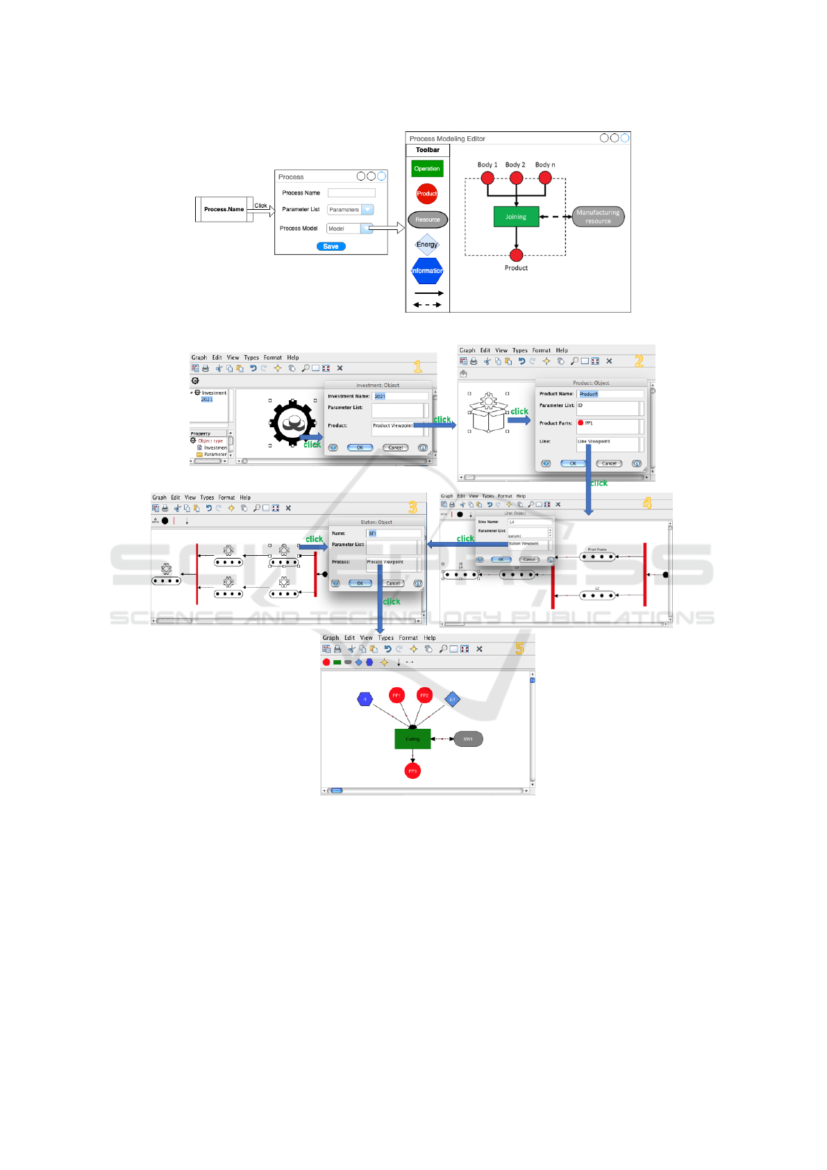
Figure 12: A sample model specified using the process modeling viewpoint notation set.
Figure 13: ManLang’s modeling editor.
ogy to map the viewpoint definitions given in Sec-
tion 3 into the Metaedit+ environment. By doing
so, we obtained the modeling editor that enables to
specify the multiple-viewpoints models in accordance
with the ManLang definitions. Figure 13 shows how
ManLang’s editor can be used to specify the require-
ments for a production planning, starting with the in-
vestment requirements and ending with the process
flow model. So, the viewpoint models for any produc-
tion planning are specified separately but connected to
each other and one may traverse different viewpoint
models starting from the investment model.
The modeling editor has been extended with an
analyser that can check the viewpoint models for
completeness and completeness. The editor ensures
completeness by checking whether the viewpoint
models are specified completely with regard to the no-
tation set of the language viewpoint definitions. For
instance, the product viewpoint model that does not
have name or any product parts or the process view-
ENASE 2022 - 17th International Conference on Evaluation of Novel Approaches to Software Engineering
402

point model that does not include any resource spec-
ification are considered to be incomplete. Such in-
complete models are determined by the editor at mod-
eling time and the users are warned with meaningful
messages. The editor ensures correctness by check-
ing whether the viewpoint models are correct with
regard to the meta-model definitions. That is, each
viewpoint model needs to satisfy the multiplicity and
relationship rules between the concepts as defined in
the viewpoint meta-model. For instance, each station
viewpoint model may be composed of a single pro-
cess model and each investment viewpoint model may
be composed of a single product model. If more than
one process/product model is tried to be included, this
leads to incorrect specifications and thus the editor in-
dicates an error at modeling time.
5 PRELIMINARY EVALUATION
We prepared a usability survey using the well-
established usability questionnaire, i.e., System Us-
ability Scale (SUS) (Brooke, 1996). We prepared 10
different Yes/No questions, where participants are ex-
pected to choose a single answer. To enhance preci-
sion, we designed a scale of answers from 1 (strongly
disagree) to 5 (strongly agree). We executed our sur-
vey among the participants of our project
1
including
the practitioners from such manufacturers as TOFAS¸,
Ford Otosan, and Volvo. We initially organised a sep-
arate meeting for each manufacturer and introduced
our language and its toolset. Then, we asked the par-
ticipants to fill in our survey that is published online
via google form. In total, we got 13 participations for
our survey. Some of the interesting survey results are
listed below.
• 46% of the participants can frequently use Man-
Lang for the modeling of production planning re-
quirements, while another 46% are unsure and
seem to have a lack of knowledge and experience
to state their agreement/disagreement.
• 67% of the participants disagree that ManLang’s
notation set is complex at all.
• 62% of the participants agree that ManLang easy
to use for the modeling of production planning re-
quirements.
• 31% of the participants think that technical sup-
port (e.g., user manual, tutorials, and help desk)
is needed to use ManLang and its toolset, while
30% do not have enough knowledge again.
• 54% of the participants agree that ManLang does
not include any inconsistencies about the lan-
guage definitions and tool support, while 31% do
not have enough knowledge.
• 76% of the participants agree that most people
would learn to use ManLang very quickly.
• 67% of the participants disagree that ManLang is
cumbersome to use.
• 42% of the participants agree that they can con-
fidently use ManLang, while 25% do not have
enough knowledge and another 33% disagree.
• 31% of the participants disagree that they need to
learn a lot of things before they could get going
with ManLang, while another 39% do not have
enough knowledge.
It should be noted that we consider the survey
results to have some initial idea about industry’s
thoughts on ManLang. To be able to receive more
precise feedback, we are planning to conduct one-to-
one interview with each participant where the partici-
pant will be asked to spend some time with ManLang
and its editor via simple case-studies and share their
thoughts over a set of open-ended questions.
6 CONCLUSIONS
In this paper, a new modeling language called Man-
Lang has been proposed for specifying the production
planning requirements early at the beginning of man-
ufacturing. ManLang offers a graphical notation set
for multiple-viewpoints modeling, which offers a sep-
arate (sub-)notation set for 5 different viewpoints (in-
vestment, product, production line, workstation, and
process). The investment viewpoint is concerned with
the information regarding the investment to be made
for any product manufacturing, the product viewpoint
is concerned with the parts composing the products
and any requirements data describing the product and
its parts, the line viewpoint is concerned with the con-
figuration of the production lines and their require-
ments data, the station viewpoint is concerned with
the configurations of the workstations for each line
and any data about the stations, and lastly the process
viewpoint is concerned with the resources involved in
each station which perform processes on the product
parts, energy, information so as to produce some out-
put. ManLang is further supported with a modeling
editor, which enables to specify the viewpoint models
separately while establishing the traceability links be-
tween them. The editor tool also enables to check the
viewpoint models in accordance with the wellformed-
ness rules defined in each viewpoint meta-model.
Our short-term goal is to conduct interview ses-
sions with a group of practitioners to improve the
ManLang: A Requirements Modeling Language for the Production Planning in Manufacturing
403

language definitions. We will also develop a model
transformation tool using the Metaedit+ technologies
so as to transform the ManLang models in accor-
dance with the AutomationML standard (Drath et al.,
2008), which is supported by other manufacturing
tools and thus enables to process the modeled re-
quirements in ManLang by different tools. We will
further extend ManLang for the specifications of re-
source behaviours (e.g., spot welding robots) and de-
velop a transformation tool for Modelica (Mattsson
et al., 1998) which enables to use the simulation tools
that support Modelica.
ACKNOWLEDGEMENTS
This work is part of the AITOC (Artificial Intelligence
supported Tool Chain in Manufacturing Engineering)
project supported by European ITEA and funded by
the TUBITAK TEYDEB Project No: 9200078.
REFERENCES
Brauer, W., Reisig, W., and Rozenberg, G., editors (1987).
Petri Nets: Central Models and Their Properties, Ad-
vances in Petri Nets 1986, Part II, Proceedings of
an Advanced Course, Bad Honnef, 8.-19. September
1986, volume 255 of Lecture Notes in Computer Sci-
ence. Springer.
Brooke, J. (1996). SUS: a “quick and dirty” usability scale.
Usability evaluation in industry, 189(3):189–194.
Chryssolouris, G., Mavrikios, D., Papakostas, N., Mourtzis,
D., Michalos, G., and Georgoulias, K. (2009). Digi-
tal manufacturing: History, perspectives, and outlook.
Proceedings of the Institution of Mechanical Engi-
neers, Part B: Journal of Engineering Manufacture,
223(5):451–462.
Drath, R., Luder, A., Peschke, J., and Hundt, L. (2008).
Automationml - the glue for seamless automation en-
gineering. In 2008 IEEE International Conference
on Emerging Technologies and Factory Automation,
pages 616–623.
Freddi, D. (2018). Digitalisation and employment in man-
ufacturing - pace of the digitalisation process and im-
pact on employment in advanced italian manufactur-
ing companies. AI Soc., 33(3):393–403.
Friedenthal, S., Moore, A., and Steiner, R. (2008). A Prac-
tical Guide to SysML: Systems Modeling Language.
Morgan Kaufmann Publishers Inc., San Francisco,
CA, USA.
Jiwei, H., Hexu, S., Tao, L., and Zhaoming, L. (2008). The
research of manufacturing execution system modeling
based on colored petri nets. In 2008 2nd International
Symposium on Systems and Control in Aerospace and
Astronautics, pages 1–4.
Kelly, S., Lyytinen, K., and Rossi, M. (2013). Metaedit+
A fully configurable multi-user and multi-tool CASE
and CAME environment. In Jr., J. A. B., Krogstie,
J., Pastor, O., Pernici, B., Rolland, C., and Sølvberg,
A., editors, Seminal Contributions to Information Sys-
tems Engineering, 25 Years of CAiSE, pages 109–129.
Springer.
Kroll, H., Horvat, D., and J
¨
ager, A. (2018). Effects of au-
tomatisation and digitalisation on manufacturing com-
panies’ production efficiency and innovation perfor-
mance. Fraunhofer ISI Discussion Papers - Inno-
vation Systems and Policy Analysis 58, Karlsruhe.
urn:nbn:de:0011-n-4873361.
L
¨
utjen, M. and Rippel, D. (2015). Gramosa framework
for graphical modelling and simulation-based analy-
sis of complex production processes. The Interna-
tional Journal of Advanced Manufacturing Technol-
ogy, 81(1):171–181.
Mattsson, S. E., Elmqvist, H., and Otter, M. (1998). Phys-
ical system modeling with modelica. Control Engi-
neering Practice, 6(4):501–510.
Petrasch, R. and Hentschke, R. (2016). Process modeling
for industry 4.0 applications: Towards an industry 4.0
process modeling language and method. In 2016 13th
International Joint Conference on Computer Science
and Software Engineering (JCSSE), pages 1–5.
Rumbaugh, J., Jacobson, I., and Booch, G. (2004). Uni-
fied Modeling Language Reference Manual, The (2Nd
Edition). Pearson Higher Education.
Seidewitz, E. (2003). What models mean. IEEE Software,
20(5):26–32.
Vjestica, M., Dimitrieski, V., Pisaric, M., Kordic, S., Ris-
tic, S., and Lukovic, I. (2020). An application of
a DSML in industry 4.0 production processes. In
Lalic, B., Majstorovic, V. D., Marjanovic, U., von
Cieminski, G., and Romero, D., editors, Advances in
Production Management Systems. The Path to Digital
Transformation and Innovation of Production Man-
agement Systems - IFIP WG 5.7 International Con-
ference, APMS 2020, Novi Sad, Serbia, August 30 -
September 3, 2020, Proceedings, Part I, volume 591
of IFIP Advances in Information and Communication
Technology, pages 441–448. Springer.
V
¨
olzer, H. (2010). An overview of BPMN 2.0 and its poten-
tial use. In Mendling, J., Weidlich, M., and Weske, M.,
editors, Business Process Modeling Notation - Second
International Workshop, BPMN 2010, Potsdam, Ger-
many, October 13-14, 2010. Proceedings, volume 67
of Lecture Notes in Business Information Processing,
pages 14–15. Springer.
Weissenberger, B., Flad, S., Chen, X., R
¨
osch, S., Voigt,
T., and Vogel-Heuser, B. (2015). Model driven en-
gineering of manufacturing execution systems using
a formal specification. In 20th IEEE Conference on
Emerging Technologies & Factory Automation, ETFA
2015, Luxembourg, September 8-11, 2015, pages 1–8.
IEEE.
Whittle, J., Hutchinson, J., and Rouncefield, M. (2014). The
state of practice in model-driven engineering. IEEE
Software, 31(3):79–85.
Witsch, M. and Vogel-Heuser, B. (2012). Towards a formal
specification framework for manufacturing execution
systems. IEEE Trans. Ind. Informatics, 8(2):311–320.
ENASE 2022 - 17th International Conference on Evaluation of Novel Approaches to Software Engineering
404
