
Lane Departure Warning System using Standard GPS Technology
and V2V Communication
Md Touhid Hossain, Shahnewaz Chowdhury and M. I. Hayee
Department of Electrical Engineering, University of Minnesota Duluth, Duluth, Minnesota, U.S.A.
Keywords: Lane Departure Warning, GPS, Road Reference Heading, V2V, DSRC.
Abstract: Lane departure warning system (LDWS) has significant potential to reduce crashes. Generally, an LDWS
uses various image processing techniques or global positioning system (GPS) technology with lane-level
resolution maps. However, these are expensive to implement and have performance limitations, such as harsh
weather or irregular lane markings can drastically reduce their performances. Previously, we developed an
LDWS which generated road reference heading (RRH) from a vehicle’s past travel trajectories acquired by
GPS to detect unintentional lane departure. However, when a vehicle travels for the first time on a given road,
it does not have any past trajectory to generate the RRH needed to detect unintentional lane departure. To
overcome this limitation, we have augmented our previously developed LDWS by adding a vehicle to vehicle
(V2V) communication feature to it, which can acquire the required RRH from a nearby vehicle via V2V
communication. We have extensively tested the V2V communication feature of our current LDWS in the
field to evaluate its performance in real-time. Test results show that the RRH of a given road can be
successfully transferred from one vehicle to another on demand, and the LDWS can detect each unintentional
lane departure accurately in a timely manner.
1 INTRODUCTION
All modern vehicles are equipped with different
Advanced Driver Assistance Systems (ADAS) to
improve safe driving (Maag et al., 2012). Lane
departure warning is one of the most important
ADAS features which can prevent accidents on
highways and freeways when a vehicle is about to
unintentionally drift away from its lane. According to
American Association of State Highway and
Transportation Officials (AASHTO) almost 60% of
the fatal accidents are caused by an unintentional lane
drifting of a vehicle on major roads (Officials, 2008).
In a recent study which compared crashes with and
without a lane departure warning system (LDWS), it
was found that an in-vehicle LDWS was helpful in
reducing crashes of all severities by 18%, with
injuries by 24%, and with fatalities by 86% without
considering for driver demographics (Cicchino,
2018).
Most available lane departure warning systems
typically use a single camera and a processor to
identify the imminent lane departure (Hsiao & Yeh,
2006) (An et al., 2006) (Yu et al., 2008) (Leng &
Chen, 2010) while other modern systems use optical
scanning and Light Detection and Ranging (LIDAR)
sensors (Lindner et al., 2009). A careful view of
camera-based systems reveals that the calibration of
a camera is an important element. However, there are
systems available that can detect the lateral offset of
a vehicle even with an uncalibrated camera (Jung &
Kelber, 2005). Most of these camera-based systems
use different image processing techniques such as
linear parabolic lane model (Jung & Kelber, 2004) or
the extended edge-linking algorithm (Lin et al.,
2010), which extract the lane markings from
consecutive picture frames to calculate lateral shift of
a vehicle. Earlier camera-based systems were
vulnerable to lighting conditions, hence not capable
to accurately recognize the lane markings at
nighttime. However, image processing techniques
have advanced over the past couple of decades
overcoming the limitation of diminished lighting
conditions to successfully detect lane drifting even in
the low lighting or night-time (Hsiao et al., 2008). For
example, a Video-Based Lane Estimation and
Tracking (VioLET) system, which uses steerable
filters, is an efficient method for detecting solid-line
and segmented-line markings under varying lighting
and road conditions for robust and accurate lane-
marking detection (McCall & Trivedi, 2006).
80
Hossain, M., Chowdhury, S. and Hayee, M.
Lane Departure Warning System using Standard GPS Technology and V2V Communication.
DOI: 10.5220/0011043700003191
In Proceedings of the 8th International Conference on Vehicle Technology and Intelligent Transport Systems (VEHITS 2022), pages 80-87
ISBN: 978-989-758-573-9; ISSN: 2184-495X
Copyright
c
2022 by SCITEPRESS – Science and Technology Publications, Lda. All rights reserved
Similarly, optical scanning systems which comprise
of a linear array of infrared transmitting devices to
scan the lateral area of the highway for lane markings,
are inherently independent of the varying lighting
conditions (Dobler et al., 2000). Although camera and
optical sensor-based systems work well in favorable
weather and road conditions in day or night light,
their performance deteriorates when the road
conditions are not favorable such as an absent or
irregular/broken lane marking or harsh weather
conditions such as fog, rain, and snow resulting in
inaccurate lane departure detection. Moreover, there
are also some systems which integrate Global
Positioning System (GPS) data with a camera based
LDWS to increase the reliability of lane departure
detection in adverse road and weather conditions.
However, such systems require GPS technology,
inertial navigation sensor, and access to digital maps
of lane-level resolution to correct the GPS position
(Clanton et al., 2009), making such systems more
complex and expensive to implement.
In our previously developed LDWS, we used
standard GPS technology and developed a road
reference heading (RRH) generation algorithm which
uses a vehicle’s past trajectories on a road to generate
an RRH for that road (Shahnewaz Chowdhury et al.,
2021). By comparing the RRH of a given road with a
vehicle’s current travel trajectory on that road
obtained from a standard GPS receiver, our
developed LDWS calculates the instantaneous lateral
shift which is accumulated over time to detect any
unintentional lane departure (Faizan et al., 2019).
However, our previously developed LDWS had a
drawback in case of a vehicle traveling on a given
road for the first time, as it would not have the any
past trajectories to generate the RRH needed to detect
unintentional lane departure. In this work, we have
augmented our previously developed LDWS by
adding the feature of vehicle to vehicle (V2V)
communication. The provision of V2V
communication enables the transfer of RRH from one
vehicle to the other; provided both the vehicles are
equipped with V2V communication device. Our field
test results show that by using the RRH received from
another vehicle, our newly proposed LDWS can
detect any lane departure on a given road and issue
timely warning even if the vehicle is traveling for the
first time on that road.
The rest of the paper is organized as follows.
Section 2 describes the system architecture of the
newly developed LDWS enabled with V2V
communication feature to transfer RRH generated
from a vehicle’s past trajectories. Section 3 provides
the details about the V2V communication process,
and section 4 discusses the field test results. Finally,
section 5 states the conclusions.
2 SYSTEM ARCHITECTURE
The newly developed lane departure warning system
has both an RRH generator as well as it is equipped
with V2V communication feature to transfer RRH
from one vehicle to another on need basis. The RRH
generator can generate RRH for any given road using
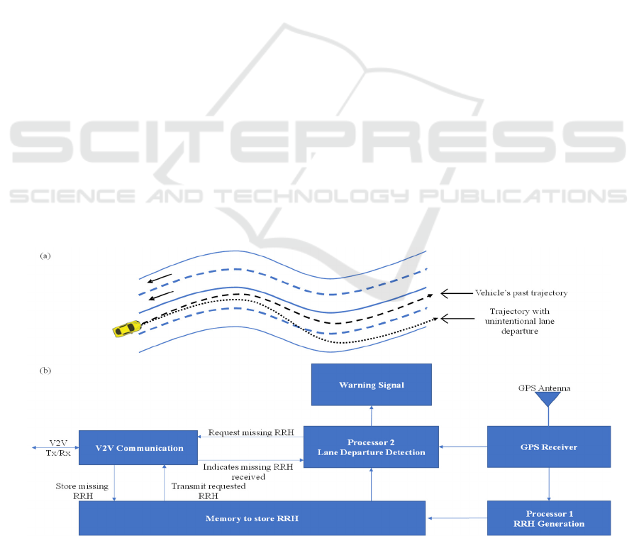
Figure 1: (a) Conceptual diagram showing how a past trajectory (black dashed line) of a given vehicle can serve to generate
RRH to detect its unintentional lane departure in future (black dotted line), and (b) the system architecture of LDWS enabled
with V2V communication to transmit or receive RRH from a nearby vehicle.
Lane Departure Warning System using Standard GPS Technology and V2V Communication
81
a vehicle’s one or more past trajectories on that road
acquired by a standard GPS receiver as shown in
schematic diagram of Figure 1a. The dashed line in
Figure 1a represents a vehicle’s past trajectory which
can be used to generate RRH for the road to detect any
unintentional lane departure as represented by the
dotted line in Figure 1a. In case if a vehicle is traveling
on a given road for the first time, it would lack any past
trajectory to generate RRH. However, if any nearby
vehicle equipped with V2V communication has the
RRH for that road, our current LDWS enables the
vehicle in need to obtain the RRH from the nearby
vehicle via V2V communication. Once an RRH for a
given road is generated or an RRH is received from a
nearby vehicle, it can be used to detect any future
unintentional lane departure on that road.
Figure 1b shows the architectural diagram of the
proposed system combining the previously developed
LDWS, and the newly added V2V communication
feature; the GPS receiver acquires longitude and
latitude of a moving vehicle’s position in real-time to
be used by both processors 1 and 2. The processor 1
uses a sufficient length of a past trajectory on a given
road whenever that is available to generate an RRH
for that road. On the other hand, processor 2 works in
real-time to detect unintentional lane departure by
using either the RRH generated by processor 1 or
RRH received from a nearby vehicle via V2V
communication. Once an RRH is generated or
received from another vehicle, it is stored in the
memory of LDWS for future lane departure detection.
This prevents processor 2 from reproducing RRH if
already available and thus improves the LDWS’s
efficiency. The V2V communication module added in
this augmented LDWS can transmit an already
generated RRH to a nearby vehicle when requested as
well as request and receive a missing RRH from a
nearby vehicle when needed.
3 V2V COMMUNICATION FOR
LDWS
The V2V communication feature added to our
proposed LDWS has overcome the drawback of not
having past trajectories to generate necessary RRH
for a first-time traveling vehicle on any given road.
To establish proper communication between two
vehicles, we have developed a V2V handshake
protocol and RRH data transfer software. This section
will highlight the design and development of V2V
communication protocol needed to exchange RRH
between two vehicles upon need.
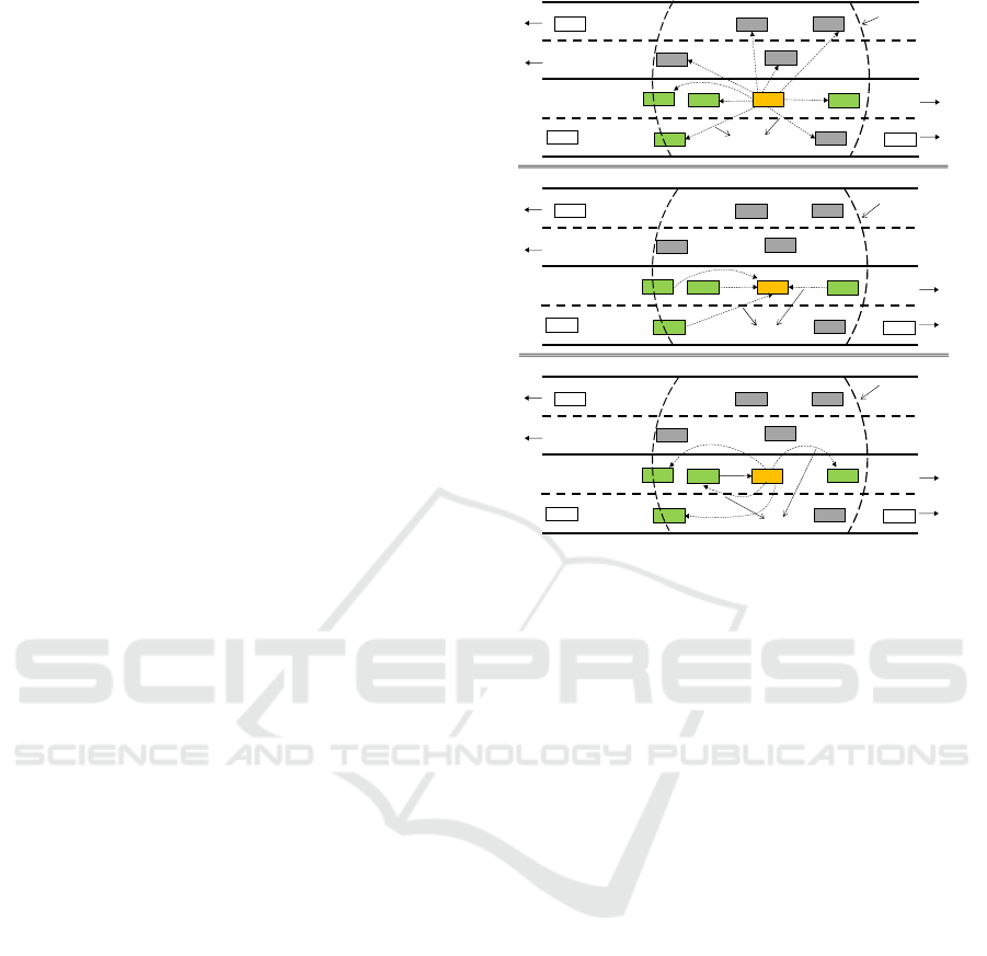
Figure 2: A scenario illustrating V2V handshake protocol
where (a) a vehicle VR in need of road reference heading
(RRH) broadcasts a REQUEST to all neighboring vehicles
within its V2V communication range, (b) all potential
candidate vehicles (colored in green) send a REPLY
message back to the requesting vehicle and (c) the
requesting vehicle VR sends a SELECT message to receive
RRH from the most suitable potential candidate vehicle
(V1).
3.1 V2V Handshake Protocol
For successful transfer of an RRH from one vehicle
to another upon request, proper V2V handshake
protocol is required to identify the most suitable
neighboring vehicle to transfer RRH to the vehicle in
need. A vehicle will request an RRH from
neighboring vehicles only when it is traveling on a
road for the very first time or does not have the RRH
for that road. One such scenario showing a vehicle V
R
traveling on a 4-lane road for the first time while not
having the RRH for that road is illustrated in Figure
2. A total of 12 neighboring vehicles (V
1
to V
12
) are
also traveling on the same road (Figure 2). The
vehicle V
R
will need the RRH for that road to detect
any unintentional lane departure. Therefore, it
broadcasts a request for the RRH by transmitting a
message called REQUEST. The REQUEST reaches
all nearby vehicles within its communication range as
shown by dashed arrows in Figure 2a. The data of
REQUEST includes the direction of travel of the
requesting vehicle (V
R
) and its location coordinates.
The direction of travel is needed to eliminate those
V
R
V
1
V
2
V
3
V
4
V
5
V
6
V
7
V
8
V
9
V
11
V
10
V
12
V2V Communication
Range of V
R
REQUEST
V
R
V
1
V
2
V
3
V
4
V
5
V
6
V
7
V
8
V
9
V
11
V
10
V
12
V2V Communication
Range of V
R
REPLY
V
R
V
1
V
2
V
3
V
4
V
5
V
6
V
7
V
8
V
9
V
1
1
V
1
0
V
12
V2V Communication
Range of V
R
SELECT
RRH
(a)
(b)
(c)
VEHITS 2022 - 8th International Conference on Vehicle Technology and Intelligent Transport Systems
82
vehicles which are traveling in the opposite direction
of the requesting vehicle (V
R
) because those vehicles
will not stay within the communication range of the
requesting vehicle long enough to complete the
handshake protocol to transfer RRH.
All neighboring vehicles receiving the REQUEST
will assess if they are traveling in the direction of the
requesting vehicle and if they have the requested
RRH to pass on. Any vehicle not having the requested
RRH or traveling in the opposite direction of the
requesting vehicle will ignore the REQUEST. Any
vehicle having the requested RRH and traveling in the
same direction as the requesting vehicle becomes a
potential candidate vehicle to transfer RRH to the
requesting vehicle (V
R
). There are 4 such potential
candidate vehicles (V
1
, V
3
, V
4
, and V
5
) shown in
green color in the scenario of Figure 2. The rest of the
vehicles (shown in grey color) are either traveling in
the opposite direction or do not have the requested
RRH. There is always a possibility to have more than
one potential candidate vehicles to transmit RRH as
in the scenario of Figure 2. In case of more than one
potential candidate vehicles having the needed RRH,
it is important that only one of those vehicles is
selected to transfer RRH to avoid broadcast
congestion. Usually, a vehicle which is the nearest to
the requesting vehicle should transfer the requested
RRH for most reliable communication. To
accomplish this, each potential candidate vehicle
calculates its distance from the requesting vehicle
(V
R
) and transmits a message called REPLY back to
the requesting vehicle as shown by dashed arrows in
Figure 2b where the same scenario of Figure 2a is
repeated showing communication paths of REPLY
messages from all potential candidate vehicles. The
data of each REPLY message from a potential
candidate vehicle includes its distance from the
requesting vehicle as well as a unique identifier (ID)
so that the requesting vehicle can distinguish among
all potential candidate vehicles.
After receiving the REPLY messages from all
potential candidate vehicles, the requesting vehicle,
V
R
selects one potential candidate vehicle at the
shortest distance. Please note that if two or more
vehicles are at the same distance, then the requesting
vehicle can randomly select any one of them. After
selecting one of the potential candidate vehicles, the
requesting vehicle (V
R
) sends a message called
SELECT back to all potential candidate vehicles as
shown in Figure 2c where the same scenario is
repeated showing the multiple communication paths
of the SELECT message to all potential candidate
vehicles. The data of the SELECT message includes
the unique ID of only one potential candidate vehicle
which is at the shortest distance from the requesting
vehicle so that all other potential candidate vehicles
can ignore this message except the one whose unique
ID is carried in this message. This will complete the
V2V handshake protocol by successfully selecting
the most suitable vehicle to transfer RRH to the
requesting vehicle. The potential candidate vehicle
with matched unique ID (V
1
in case of the given
scenario of Figure 2c) can now start transferring the
requested RRH to the requesting vehicle (VR) as
shown by a solid arrow from V
1
to V
R
in Figure 2c.
The implementation details of the V2V handshake
protocol and transfer of RRH are given in the rest of
this section.
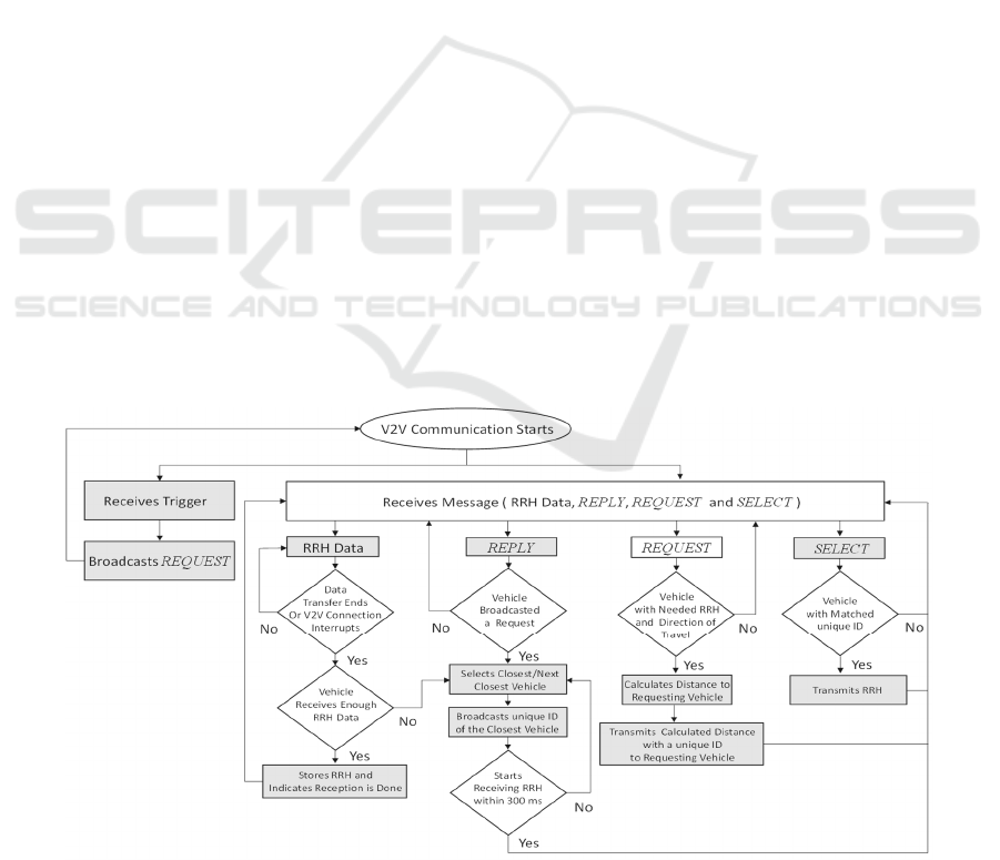
Figure 3: A flow chart of the V2V handshake protocol for a vehicle in need to receive RRH data of a given road from the
most suitable neighboring vehicle on that road.
Lane Departure Warning System using Standard GPS Technology and V2V Communication
83
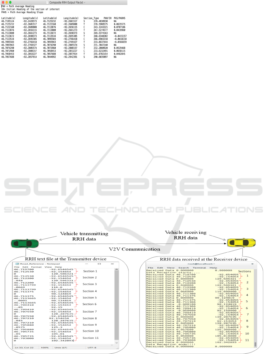
Figure 4: Screenshot of an RRH file of a given road with all
optimized parameters.
After developing the V2V handshake protocol to
identify the most suitable vehicle to transfer RRH to a
vehicle in need, we implemented this protocol in our
LDWS and did the necessary programming to
successfully demonstrate its functionality. The flow-
chart of the software to implement the newly designed
V2V handshake protocol is shown in Figure 3. Please
note that the software of flowchart given in Figure 3
will be running in each vehicle in addition to two other
previously developed software i.e., RRH generation
software and the lane departure detection software.
3.2 V2V Transfer of RRH
The handshake protocol to select the most suitable
vehicle to transfer RRH to the vehicle in need is
described above. The actual data transfer is
implemented using a dedicated short-range
communication (DSRC) based device for the
demonstration purposes. The DSRC device used has
a built in GPS receiver and necessary processing
power to run the V2V communication software as
well as software for RRH generation and LDWS
algorithms. As an alternative to DSRC based V2V
communication, cellular V2V (C-V2V)
communication could be used as well.
After the most suitable vehicle is identified and
selected, the process to transfer RRH takes place
slowly over next several cycles of DSRC
communication depending upon the amount of RRH
data. The data of RRH generated from past vehicle
trajectories using our previously developed algorithm
is included in a text file as shown in Figure 4 where a
screenshot of a typical RRH data file for a 4.2 km road
segment of the Interstate I-35 is shown. Each row
describes an individual section (straight, curve or
transition) of the road and there are 13 sections (rows)
in the given text file. Each section is defined by its
beginning and ending points (in terms of latitude and
longitude), the optimized values of relevant
parameters, and the section type. Please note that an
“N” indicates that the corresponding parameter is not
applicable to that section. This text file has the
necessary information to completely define the road
reference heading at any point along the road and can
be used by LDWS to detect any unintentional lane
departure in real-time. Although each section of the
road in RRH data file contains seven parameters to
fully characterize the given section, one of the 7
parameters (the section type shown in Figure 4) is not
necessarily needed as it can be deduced from the other
parameters. Therefore, in our developed system, each
section can be transmitted using only six parameters.
Figure 5: Screenshot of the console of the DSRC device in the transmitter vehicle (left bubble box) showing a text file of
RRH data stored in the device and screenshot of the console of the DSRC device in the receiving vehicle (right bubble box)
when the RRH data is received via DSRC based V2V communication.
VEHITS 2022 - 8th International Conference on Vehicle Technology and Intelligent Transport Systems
84
In DSRC based V2V communication, each data
transfer cycle is 100 ms and any data transfer can take
place during this cycle. We have implemented RRH
data transfer process section by section but in such a
way that only two parameters can be transferred in
one communication cycle (100 ms). As there are six
useful parameters in each section of RRH data for any
given road, we need three cycles (300 ms or 0.3 s) to
completely transfer one section. Depending upon the
number of sections of the road in an RRH text file, it
can take up to a few seconds to complete the RRH
transfer process. For example, there are 13 sections in
the RRH text file of Figure 4, therefore, it will take
3.9 seconds (13 x 0.3 s) to completely transfer all the
sections of this RRH. After successfully completing
the transfer of all the sections present in the RRH data
file, a final message is sent to the receiving vehicle to
indicate that all the data has been sent. Please note
that an additional communication cycle (0.1 s) will be
needed for the final message indicating the data
transfer completion. For some reason, if the
connection is lost before the transfer of RRH data is
completed or before enough RRH data is transferred,
our developed software can manage the situation by
restarting the process as described above in the V2V
handshake protocol.
After developing the software for V2V handshake
protocol and RRH data transfer, we evaluated this in
the lab by using two DSRC devices to simulate two
vehicles, one vehicle without the RRH and the other
with the RRH. One such lab evaluation scenario is
illustrated in Figure 5 where the vehicle shown as
yellow needs an RRH for a given road and the vehicle
shown as green has that RRH. Once the V2V
handshake protocol establishes the connection
between the two vehicles (transmitting and
receiving), the transfer of RRH data takes place
section by section. The transfer of the RRH data is
also illustrated in Figure 5 where the screenshots of
the consoles of the two DSRC devices of the two
corresponding vehicles are also shown. The left-side
console is for the transmitting vehicle’s device and
shows the actual RRH data which is being transmitted
to the other vehicle. The right-side console is for the
device of the receiving vehicle and shows the actual
received RRH data by the receiving vehicle’s device.
There are 11 sections in the RRH of the text file used
in this lab evaluation which was successfully
transmitted in a total of 3.4 seconds. The transmission
of each of the 11 sections in the RRH data file took
0.3 seconds so all 11 sections were successfully
transmitted in 3.3 seconds (11 x 0.3 s). The final
message (in the form of two consecutive zeros) took
another 0.1 second indicating that the transfer was
complete.
4 FIELD TESTS AND RESULTS
After successfully developing and testing V2V
handshake and data transfer software in the lab, we
wanted to evaluate both in the field to detect
unintentional lane departures. We have been using a
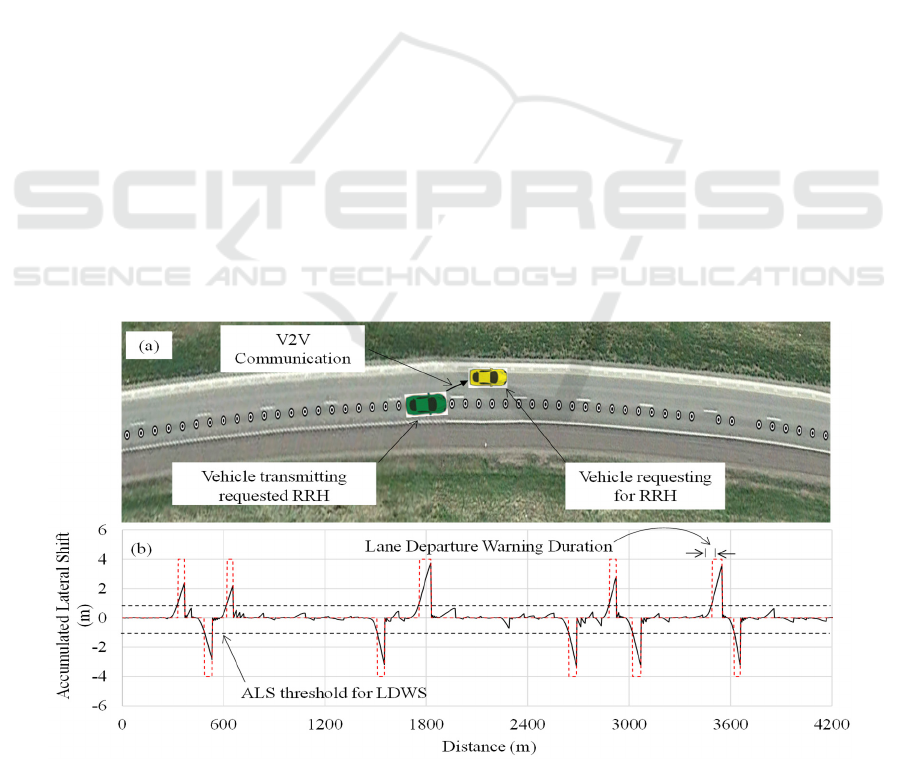
Figure 6: (a) A typical V2V communication scenario for transferring RRH data, and (b) ALS vs. traveled distance for a test
run on the 4.2 km road segment of interstate I-35 with 10 lane changes. The red dashed line in (b) represents a digital mask
for the duration of audible warning and the two black dashed lines in (b) represent ALS threshold for LDWS.
Lane Departure Warning System using Standard GPS Technology and V2V Communication
85

4.2 km long road segment of the Interstate I-35 for
our previous field tests for which we have already
generated an RRH. We used the same road segment
to test the V2V handshake protocol and RRH data
transfer software. The complete field test involves
driving at least two test vehicles, one of these two
vehicles without having the RRH data file in its
DSRC device and running only lane departure
warning software while the other vehicle having the
required RRH data file in its DSRC device. The two
vehicles should be driven within the DSRC
communication range of each other on the same road.
We wanted to drive two test vehicles in close
proximity on our test road segment as shown in
Figure 6a. However, because of the Covid-19, we
were not able to go to the field as it required at least
two people in each of the two vehicles for a prolonged
period. Instead, we used an innovative method to test
the full operation of all the pieces of our developed
software including V2V handshake protocol, RRH
data transfer, and lane departure detection. We had
previously acquired and stored multiple GPS
trajectories of a test vehicle on our test road segment.
We used two such separate trajectories of two
vehicles driven in proximity of each other on the test
road segment and stored them in two separate DSRC
devices. The two DSRC devices represented two test
vehicles traveling on the actual road. Each of the two
DSRC devices was operated normally in the lab
except that every new GPS point acquired by the GPS
receiver of the corresponding DSRC device was
replaced with one of the GPS points in stored
trajectory. By doing this, each DSRC device appeared
to be as it was being driven on the actual road. The
DSRC device of one of the two vehicles (shown as
yellow in Figure 6a) was running the lane departure
detection software but did not have the corresponding
RRH of that road segment so it needed to request
RRH from a neighboring vehicle to detect lane
departure and issue an audible warning. The other
vehicle (shown as green in Figure 6a) acted as a
neighboring vehicle having the necessary RRH data
file in its DSRC device. In this test, only one of the
two vehicles (yellow) without the needed RRH data
file was tested for lane departure detection algorithm
after successfully receiving the RRH data file from
the neighboring vehicle (green).
Our lane departure detection algorithm calculates
lateral shift of the test vehicle by comparing its
calculated heading with the RRH of that road in real-
time. The instantaneous lateral shift is accumulated
over time and when the accumulated lateral shift
(ALS) crosses 1 m threshold, an audible warning is
issued. When a vehicle intentionally changes its lane,
the increase in lateral distance saturates upon
completion of its lane change because the vehicle
starts to travel again in parallel to the RRH of the
road. This phenomenon is used to reset the ALS to
zero after every lane change to detect a future lane
change or unintentional lane departure.
We used two test vehicles’ trajectories on the
same road segment with the trajectory of one vehicle
having many lane changes present in it to test lane
departure detection and warning. Please note that in
all our field tests, we used lane change to test
unintentional lane departure warning for safety
reasons. One of the two test vehicles or the DSRC
devices did not have the necessary RRH while the
other vehicle or the DSRC device had the necessary
RRH data file, and both were always driven in
proximity of each other to ensure DSRC connection.
In each new test drive, the vehicle running the lane
departure software successfully obtained the required
RRH from the neighboring vehicle using our
developed V2V handshake protocol and RRH data
transfer software. After obtaining the required RRH,
a lane departure warning was issued upon each lane
change.
Although, we have tested our LDWS on a freeway
with two lanes each direction, our algorithm design is
not restricted to number of lanes of the road.
Furthermore, roadside units (RSU) if available can be
used to transfer RRH when traffic density is too low
or V2V communication equipped vehicles are absent
within the range of communication.
For one such test run, the calculated ALS versus
traveled distance is shown in Figure 6b. Our lane
departure warning software issued audible warning
upon each of the 10 lane changes whenever ALS
crossed the 1 m threshold as shown by dashed black
line in Figure 6b. A digital mask for audible lane
departure warning signal is also superimposed in
Figure 6b with dashed red line showing the start and
end of the lane departure warning signal for each of
the 10 lane changes. Lane departure audible warning
signal becomes active when ALS crosses the
threshold (1m) and is deactivated when the vehicle
heading becomes parallel to the RRH of the road. In
each of the 10 lane changes, our algorithm accurately
detected all lane departures (or lane changes) in a
timely manner and nowhere else along the trajectory,
ALS crossed the threshold showing no false alarms.
5 CONCLUSIONS
In this work, we have successfully augmented our
previously developed LDWS by adding a V2V
VEHITS 2022 - 8th International Conference on Vehicle Technology and Intelligent Transport Systems
86

communication feature to transfer RRH from one
vehicle to another. We have designed a V2V
handshake protocol and developed the corresponding
software to facilitate proper communication among
neighboring vehicles to select and transfer RRH from
one vehicle to another upon request. We have used
two DSRC devices simulating the two vehicles in the
lab to test our developed V2V handshake protocol
and RRH data transfer software. Please note that
instead of DSRC based V2V communication, C-V2V
communication can also be used to test our software.
After developing and extensively testing our
software, we have performed field tests to
successfully detect lane departures using the RRH
received via V2V communication. The V2V
communication based LDWS can be successfully
implemented in large scale if the market penetration
of V2V communication enabled vehicles reaches a
critical level which is not there as of now. As an
alternative to V2V communication, the developed
LDWS can also be integrated into popular
smartphone apps e.g., Waze, Google Maps or Apple
Maps to take advantage of the vast database of
multiple GPS trajectories which can be used to
generate RRH for almost all roads making it available
for a vehicle to detect its unintentional lane departure
on any road even if the vehicle is driven on that road
for the first time.
REFERENCES
An, X., Wu, M., & He, H. (2006). A novel approach to
provide lane departure warning using only one forward-
looking camera. International Symposium on
Collaborative Technologies and Systems (CTS’06),
356–362.
Cicchino, J. B. (2018). Effects of lane departure warning on
police-reported crash rates. Journal of Safety Research,
66, 61–70.
Clanton, J. M., Bevly, D. M., & Hodel, A. S. (2009). A low-
cost solution for an integrated multisensor lane
departure warning system. IEEE Transactions on
Intelligent Transportation Systems, 10(1), 47–59.
Dobler, G., Rothe, S., Betzitza, P., & Hartlieb, M. (2000).
Vehicle with optical scanning device for a lateral road
area. Google Patents.
Faizan, M., Hussain, S., & Hayee, M. I. (2019). Design and
development of in-vehicle lane departure warning
system using standard global positioning system
receiver. Transportation Research Record, 2673(8),
648–656.
Hsiao, P.-Y., & Yeh, C.-W. (2006). A portable real-time
lane departure warning system based on embedded
calculating technique. 2006 IEEE 63rd Vehicular
Technology Conference, 6, 2982–2986.
Hsiao, P.-Y., Yeh, C.-W., Huang, S.-S., & Fu, L.-C. (2008).
A portable vision-based real-time lane departure
warning system: Day and night. IEEE Transactions on
Vehicular Technology, 58(4), 2089–2094.
Jung, C. R., & Kelber, C. R. (2004). A lane departure
warning system based on a linear-parabolic lane model.
IEEE Intelligent Vehicles Symposium, 2004, 891–895.
Jung, C. R., & Kelber, C. R. (2005). A lane departure
warning system using lateral offset with uncalibrated
camera. Proceedings. 2005 IEEE Intelligent
Transportation Systems, 2005., 102–107.
Leng, Y.-C., & Chen, C.-L. (2010). Vision-based lane
departure detection system in urban traffic scenes. 2010
11th International Conference on Control Automation
Robotics & Vision, 1875–1880.
Lin, Q., Han, Y., & Hahn, H. (2010). Real-time lane
departure detection based on extended edge-linking
algorithm. 2010 Second International Conference on
Computer Research and Development, 725–730.
Lindner, P., Richter, E., Wanielik, G., Takagi, K., & Isogai,
A. (2009). Multi-channel lidar processing for lane
detection and estimation. 2009 12th International IEEE
Conference on Intelligent Transportation Systems, 1–6.
Maag, C., Muhlbacher, D., Mark, C., & Kruger, H.-P.
(2012). Studying effects of advanced driver assistance
systems (ADAS) on individual and group level using
multi-driver simulation. IEEE Intelligent
Transportation Systems Magazine, 4(3), 45–54.
McCall, J. C., & Trivedi, M. M. (2006). Video-based lane
estimation and tracking for driver assistance: Survey,
system, and evaluation. IEEE Transactions on
Intelligent Transportation Systems, 7(1), 20–37.
Officials, T. (2008). Driving Down Lane-departure
Crashes: A National Priority. AASHTO.
Shahnewaz Chowdhury, M., Hossain, T., & Hayee, M. I.
(2021). Generation of Road Reference Heading using
GPS Trajectories for Accurate Lane Departure
Detection.
Yu, B., Zhang, W., & Cai, Y. (2008). A lane departure
warning system based on machine vision. 2008 IEEE
Pacific-Asia Workshop on Computational Intelligence
and Industrial Application, 1, 197–201.
Lane Departure Warning System using Standard GPS Technology and V2V Communication
87
